EP1567760B1 - Procede pour commander un moteur a combustion interne a injection directe de carburant - Google Patents
Procede pour commander un moteur a combustion interne a injection directe de carburant Download PDFInfo
- Publication number
- EP1567760B1 EP1567760B1 EP03753333A EP03753333A EP1567760B1 EP 1567760 B1 EP1567760 B1 EP 1567760B1 EP 03753333 A EP03753333 A EP 03753333A EP 03753333 A EP03753333 A EP 03753333A EP 1567760 B1 EP1567760 B1 EP 1567760B1
- Authority
- EP
- European Patent Office
- Prior art keywords
- mff
- internal combustion
- combustion engine
- fuel
- injected
- Prior art date
- Legal status (The legal status is an assumption and is not a legal conclusion. Google has not performed a legal analysis and makes no representation as to the accuracy of the status listed.)
- Expired - Lifetime
Links
- 238000002485 combustion reaction Methods 0.000 title claims description 93
- 239000000446 fuel Substances 0.000 title claims description 75
- 238000002347 injection Methods 0.000 title claims description 43
- 239000007924 injection Substances 0.000 title claims description 43
- 238000000034 method Methods 0.000 title claims description 24
- 230000006835 compression Effects 0.000 claims description 20
- 238000007906 compression Methods 0.000 claims description 20
- 238000006073 displacement reaction Methods 0.000 claims 1
- 239000007789 gas Substances 0.000 description 17
- 238000010586 diagram Methods 0.000 description 5
- 230000000694 effects Effects 0.000 description 5
- 239000000203 mixture Substances 0.000 description 5
- 238000010926 purge Methods 0.000 description 5
- 238000011049 filling Methods 0.000 description 4
- 230000003197 catalytic effect Effects 0.000 description 3
- 239000002826 coolant Substances 0.000 description 3
- 238000001816 cooling Methods 0.000 description 3
- 238000012937 correction Methods 0.000 description 3
- 238000009826 distribution Methods 0.000 description 3
- 238000001704 evaporation Methods 0.000 description 3
- 230000008020 evaporation Effects 0.000 description 3
- 238000012545 processing Methods 0.000 description 3
- 239000000523 sample Substances 0.000 description 3
- 230000008901 benefit Effects 0.000 description 2
- 230000001276 controlling effect Effects 0.000 description 2
- 230000007423 decrease Effects 0.000 description 2
- 230000001419 dependent effect Effects 0.000 description 2
- 230000002349 favourable effect Effects 0.000 description 2
- 238000011010 flushing procedure Methods 0.000 description 2
- 239000008240 homogeneous mixture Substances 0.000 description 2
- 230000001105 regulatory effect Effects 0.000 description 2
- 230000002000 scavenging effect Effects 0.000 description 2
- 238000009834 vaporization Methods 0.000 description 2
- 230000008016 vaporization Effects 0.000 description 2
- 238000010521 absorption reaction Methods 0.000 description 1
- 230000002411 adverse Effects 0.000 description 1
- 230000015572 biosynthetic process Effects 0.000 description 1
- 239000003054 catalyst Substances 0.000 description 1
- 230000008859 change Effects 0.000 description 1
- 230000003111 delayed effect Effects 0.000 description 1
- 238000011161 development Methods 0.000 description 1
- 230000018109 developmental process Effects 0.000 description 1
- 239000003344 environmental pollutant Substances 0.000 description 1
- 239000000284 extract Substances 0.000 description 1
- 239000003925 fat Substances 0.000 description 1
- 238000010304 firing Methods 0.000 description 1
- 230000005484 gravity Effects 0.000 description 1
- 238000005457 optimization Methods 0.000 description 1
- 231100000719 pollutant Toxicity 0.000 description 1
- 238000002360 preparation method Methods 0.000 description 1
- 230000008569 process Effects 0.000 description 1
- 230000009467 reduction Effects 0.000 description 1
- 230000004044 response Effects 0.000 description 1
- 238000000926 separation method Methods 0.000 description 1
- 239000000779 smoke Substances 0.000 description 1
- 238000003860 storage Methods 0.000 description 1
- 238000012360 testing method Methods 0.000 description 1
- 230000001052 transient effect Effects 0.000 description 1
- 238000011144 upstream manufacturing Methods 0.000 description 1
Images

Classifications
-
- F—MECHANICAL ENGINEERING; LIGHTING; HEATING; WEAPONS; BLASTING
- F02—COMBUSTION ENGINES; HOT-GAS OR COMBUSTION-PRODUCT ENGINE PLANTS
- F02D—CONTROLLING COMBUSTION ENGINES
- F02D13/00—Controlling the engine output power by varying inlet or exhaust valve operating characteristics, e.g. timing
- F02D13/02—Controlling the engine output power by varying inlet or exhaust valve operating characteristics, e.g. timing during engine operation
- F02D13/0261—Controlling the valve overlap
-
- F—MECHANICAL ENGINEERING; LIGHTING; HEATING; WEAPONS; BLASTING
- F02—COMBUSTION ENGINES; HOT-GAS OR COMBUSTION-PRODUCT ENGINE PLANTS
- F02B—INTERNAL-COMBUSTION PISTON ENGINES; COMBUSTION ENGINES IN GENERAL
- F02B37/00—Engines characterised by provision of pumps driven at least for part of the time by exhaust
- F02B37/12—Control of the pumps
- F02B37/18—Control of the pumps by bypassing exhaust from the inlet to the outlet of turbine or to the atmosphere
-
- F—MECHANICAL ENGINEERING; LIGHTING; HEATING; WEAPONS; BLASTING
- F02—COMBUSTION ENGINES; HOT-GAS OR COMBUSTION-PRODUCT ENGINE PLANTS
- F02D—CONTROLLING COMBUSTION ENGINES
- F02D23/00—Controlling engines characterised by their being supercharged
- F02D23/02—Controlling engines characterised by their being supercharged the engines being of fuel-injection type
-
- F—MECHANICAL ENGINEERING; LIGHTING; HEATING; WEAPONS; BLASTING
- F02—COMBUSTION ENGINES; HOT-GAS OR COMBUSTION-PRODUCT ENGINE PLANTS
- F02D—CONTROLLING COMBUSTION ENGINES
- F02D35/00—Controlling engines, dependent on conditions exterior or interior to engines, not otherwise provided for
- F02D35/02—Controlling engines, dependent on conditions exterior or interior to engines, not otherwise provided for on interior conditions
- F02D35/027—Controlling engines, dependent on conditions exterior or interior to engines, not otherwise provided for on interior conditions using knock sensors
-
- F—MECHANICAL ENGINEERING; LIGHTING; HEATING; WEAPONS; BLASTING
- F02—COMBUSTION ENGINES; HOT-GAS OR COMBUSTION-PRODUCT ENGINE PLANTS
- F02D—CONTROLLING COMBUSTION ENGINES
- F02D41/00—Electrical control of supply of combustible mixture or its constituents
- F02D41/0002—Controlling intake air
-
- F—MECHANICAL ENGINEERING; LIGHTING; HEATING; WEAPONS; BLASTING
- F02—COMBUSTION ENGINES; HOT-GAS OR COMBUSTION-PRODUCT ENGINE PLANTS
- F02D—CONTROLLING COMBUSTION ENGINES
- F02D41/00—Electrical control of supply of combustible mixture or its constituents
- F02D41/30—Controlling fuel injection
- F02D41/38—Controlling fuel injection of the high pressure type
- F02D41/40—Controlling fuel injection of the high pressure type with means for controlling injection timing or duration
- F02D41/402—Multiple injections
-
- F—MECHANICAL ENGINEERING; LIGHTING; HEATING; WEAPONS; BLASTING
- F02—COMBUSTION ENGINES; HOT-GAS OR COMBUSTION-PRODUCT ENGINE PLANTS
- F02B—INTERNAL-COMBUSTION PISTON ENGINES; COMBUSTION ENGINES IN GENERAL
- F02B75/00—Other engines
- F02B75/12—Other methods of operation
- F02B2075/125—Direct injection in the combustion chamber for spark ignition engines, i.e. not in pre-combustion chamber
-
- F—MECHANICAL ENGINEERING; LIGHTING; HEATING; WEAPONS; BLASTING
- F02—COMBUSTION ENGINES; HOT-GAS OR COMBUSTION-PRODUCT ENGINE PLANTS
- F02B—INTERNAL-COMBUSTION PISTON ENGINES; COMBUSTION ENGINES IN GENERAL
- F02B29/00—Engines characterised by provision for charging or scavenging not provided for in groups F02B25/00, F02B27/00 or F02B33/00 - F02B39/00; Details thereof
- F02B29/04—Cooling of air intake supply
- F02B29/0406—Layout of the intake air cooling or coolant circuit
- F02B29/0437—Liquid cooled heat exchangers
-
- F—MECHANICAL ENGINEERING; LIGHTING; HEATING; WEAPONS; BLASTING
- F02—COMBUSTION ENGINES; HOT-GAS OR COMBUSTION-PRODUCT ENGINE PLANTS
- F02D—CONTROLLING COMBUSTION ENGINES
- F02D41/00—Electrical control of supply of combustible mixture or its constituents
- F02D41/0002—Controlling intake air
- F02D2041/001—Controlling intake air for engines with variable valve actuation
-
- F—MECHANICAL ENGINEERING; LIGHTING; HEATING; WEAPONS; BLASTING
- F02—COMBUSTION ENGINES; HOT-GAS OR COMBUSTION-PRODUCT ENGINE PLANTS
- F02D—CONTROLLING COMBUSTION ENGINES
- F02D41/00—Electrical control of supply of combustible mixture or its constituents
- F02D41/30—Controlling fuel injection
- F02D41/38—Controlling fuel injection of the high pressure type
- F02D2041/389—Controlling fuel injection of the high pressure type for injecting directly into the cylinder
-
- F—MECHANICAL ENGINEERING; LIGHTING; HEATING; WEAPONS; BLASTING
- F02—COMBUSTION ENGINES; HOT-GAS OR COMBUSTION-PRODUCT ENGINE PLANTS
- F02D—CONTROLLING COMBUSTION ENGINES
- F02D41/00—Electrical control of supply of combustible mixture or its constituents
- F02D41/0002—Controlling intake air
- F02D41/0007—Controlling intake air for control of turbo-charged or super-charged engines
-
- F—MECHANICAL ENGINEERING; LIGHTING; HEATING; WEAPONS; BLASTING
- F02—COMBUSTION ENGINES; HOT-GAS OR COMBUSTION-PRODUCT ENGINE PLANTS
- F02D—CONTROLLING COMBUSTION ENGINES
- F02D41/00—Electrical control of supply of combustible mixture or its constituents
- F02D41/02—Circuit arrangements for generating control signals
- F02D41/04—Introducing corrections for particular operating conditions
- F02D41/10—Introducing corrections for particular operating conditions for acceleration
-
- F—MECHANICAL ENGINEERING; LIGHTING; HEATING; WEAPONS; BLASTING
- F02—COMBUSTION ENGINES; HOT-GAS OR COMBUSTION-PRODUCT ENGINE PLANTS
- F02D—CONTROLLING COMBUSTION ENGINES
- F02D41/00—Electrical control of supply of combustible mixture or its constituents
- F02D41/02—Circuit arrangements for generating control signals
- F02D41/14—Introducing closed-loop corrections
- F02D41/1438—Introducing closed-loop corrections using means for determining characteristics of the combustion gases; Sensors therefor
- F02D41/1444—Introducing closed-loop corrections using means for determining characteristics of the combustion gases; Sensors therefor characterised by the characteristics of the combustion gases
- F02D41/1454—Introducing closed-loop corrections using means for determining characteristics of the combustion gases; Sensors therefor characterised by the characteristics of the combustion gases the characteristics being an oxygen content or concentration or the air-fuel ratio
-
- F—MECHANICAL ENGINEERING; LIGHTING; HEATING; WEAPONS; BLASTING
- F02—COMBUSTION ENGINES; HOT-GAS OR COMBUSTION-PRODUCT ENGINE PLANTS
- F02D—CONTROLLING COMBUSTION ENGINES
- F02D41/00—Electrical control of supply of combustible mixture or its constituents
- F02D41/30—Controlling fuel injection
- F02D41/3011—Controlling fuel injection according to or using specific or several modes of combustion
- F02D41/3017—Controlling fuel injection according to or using specific or several modes of combustion characterised by the mode(s) being used
- F02D41/3023—Controlling fuel injection according to or using specific or several modes of combustion characterised by the mode(s) being used a mode being the stratified charge spark-ignited mode
-
- Y—GENERAL TAGGING OF NEW TECHNOLOGICAL DEVELOPMENTS; GENERAL TAGGING OF CROSS-SECTIONAL TECHNOLOGIES SPANNING OVER SEVERAL SECTIONS OF THE IPC; TECHNICAL SUBJECTS COVERED BY FORMER USPC CROSS-REFERENCE ART COLLECTIONS [XRACs] AND DIGESTS
- Y02—TECHNOLOGIES OR APPLICATIONS FOR MITIGATION OR ADAPTATION AGAINST CLIMATE CHANGE
- Y02T—CLIMATE CHANGE MITIGATION TECHNOLOGIES RELATED TO TRANSPORTATION
- Y02T10/00—Road transport of goods or passengers
- Y02T10/10—Internal combustion engine [ICE] based vehicles
- Y02T10/12—Improving ICE efficiencies
-
- Y—GENERAL TAGGING OF NEW TECHNOLOGICAL DEVELOPMENTS; GENERAL TAGGING OF CROSS-SECTIONAL TECHNOLOGIES SPANNING OVER SEVERAL SECTIONS OF THE IPC; TECHNICAL SUBJECTS COVERED BY FORMER USPC CROSS-REFERENCE ART COLLECTIONS [XRACs] AND DIGESTS
- Y02—TECHNOLOGIES OR APPLICATIONS FOR MITIGATION OR ADAPTATION AGAINST CLIMATE CHANGE
- Y02T—CLIMATE CHANGE MITIGATION TECHNOLOGIES RELATED TO TRANSPORTATION
- Y02T10/00—Road transport of goods or passengers
- Y02T10/10—Internal combustion engine [ICE] based vehicles
- Y02T10/40—Engine management systems
Definitions
- the invention relates to a method for controlling an internal combustion engine provided with a supercharging device and operating with direct fuel injection.
- a fuel pressure controlled by the electronic control unit of the internal combustion engine via pressure sensor and pressure regulator in the distributor rail is constructed by means of a high-pressure pump, which is largely independent of speed and injection quantity available.
- the fuel is injected into the combustion chamber via an electrically controllable injector. This receives its signals from the controller. Due to the functional separation of pressure generation and injection, the injection pressure can be selected largely independently of the current operating point of the internal combustion engine.
- WO 00/52317 discloses a corresponding system in which an amount of fuel to be injected is divided into two subsets, wherein a first subset is injected into an intake stroke and a second subset into a compression stroke.
- the quantity ratio between the subsets is set depending on engine operating conditions and a knock tendency.
- a charging device which increases the amount of charge by pre-compression.
- a supercharger promotes the fresh air into the cylinder of the internal combustion engine.
- the compressor is driven directly by the internal combustion engine (eg compressor supercharging), while in the case of an exhaust gas turbocharger
- a turbine exhaust gas turbine acted upon by the exhaust gas of the internal combustion engine drives a compressor located in the intake tract of the internal combustion engine.
- variable valve control of the intake and exhaust valves offers the possibility to adjust the valve timing within the physical limits of the existing actuator principle (mechanical system, hydraulic systems, electrical systems, pneumatic system or a combination of the systems mentioned) more or less freely. As a result, fuel savings, lower raw emissions and higher torque can be achieved.
- the invention has for its object to provide a method by which the operation of a charged and operated with direct fuel injection, a variable valve train having internal combustion engine can be improved.
- DI gasoline engine In a gasoline engine operated with a homogeneous mixture with direct fuel injection, hereinafter referred to simply as a DI gasoline engine, can be positively influenced via a division of the total fuel injection quantity, - each a partial injection in the intake and compression stroke, the achievable performance and fuel consumption.
- the offset in the compression stroke second injection quantity extracts the heat of vaporization of the mixture, which reduces the maximum combustion temperature and thereby the tendency to knocking combustion by reducing the charge temperature at the ignition. In this way, the ignition angle can be adjusted in areas of higher engine efficiency in "early direction".
- the prerequisite for this is a positive pressure gradient between inlet and outlet side at the time of charge change OT (top dead center) as well as sufficient valve overlap between exhaust port and exhaust port. Inlet valve.
- the mass flow through the turbine is increased in an exhaust gas turbocharger, as a result of which transient behavior and also increases the achievable maximum power. Due to the increased turbine capacity, the compressor coupled to the turbine also promotes a higher amount of air. The limit is the so-called absorption behavior of the internal combustion engine.
- FIG. 1 shows, in the form of a block diagram, a supercharged Otto internal combustion engine 10 with direct fuel injection and an exhaust aftertreatment system assigned to it. Only those components are shown which are necessary for the understanding of the invention. In particular, has been dispensed with the representation of the ignition system, the fuel circuit and the cooling circuit.
- the internal combustion engine 10 receives the necessary for combustion fresh air.
- the supplied fresh air flows through an air filter 12, an air mass meter 13 and a charge air cooler 14 to a throttle block 15.
- the throttle block 15 includes a throttle valve 16 and a throttle valve sensor, not shown, which outputs a 16 corresponding to the opening angle of the throttle valve signal.
- the throttle valve 16 is, for example, an electric motor-driven throttle element (e-gas) whose opening cross-section, in addition to the actuation by the driver (driver request), depends on the Operating range of the internal combustion engine via appropriate signals of a control device 17 is adjustable.
- the air mass meter 13 is used in a so-called air-mass-guided control of the internal combustion engine as a load sensor whose output signal MAF_KGH for further processing of the control device 17 is supplied.
- the internal combustion engine 10 has a fuel metering device 18 which is supplied with fuel KST under high pressure and which contains a number of injection valves corresponding to the number of cylinders of the internal combustion engine, which are actuated via corresponding signals from injection output stages, which are preferably integrated in the electronic control device 17 of the internal combustion engine , Fuel is injected directly into the cylinders of the internal combustion engine 10 via the injection valves.
- the injectors are supplied in an advantageous manner from a fuel pressure accumulator (common rail) with fuel.
- the amount of fuel injected by an injector is designated MFF.
- a pressure sensor 19 on the fuel metering device 18, detects the fuel pressure FUP, with which the fuel is injected directly into the cylinders of the internal combustion engine.
- the internal combustion engine 10 is connected to an exhaust gas channel 20, in which an exhaust gas catalyst 21 is arranged.
- an exhaust gas catalyst 21 In this case, a three-way catalytic converter or a NOx storage catalytic converter or a combination of the two can be provided.
- the sensors for the exhaust aftertreatment include i.a. a arranged upstream of the catalytic converter 21 Abgasmessaufionat in the form of a lambda probe 22nd
- the mixture is controlled according to the setpoint specifications.
- This function is performed by a known lambda control device 23, which preferably integrates into the control device 17 controlling or regulating the operation of the internal combustion engine is.
- Such electronic control devices 17, which generally include one or more microprocessors and which, in addition to the fuel injection and the ignition control, take on a large number of further control and regulating tasks, are known per se, so that in the following only those relevant in connection with the invention Structure and its functioning is received.
- the control device 17 is connected to a memory device 24, in which inter alia various maps and threshold values are stored, the meaning of which will be explained later.
- a charging device in the form of a known exhaust gas turbocharger is provided, the turbine 25 is disposed in the exhaust passage 20 and a dashed line, unspecified wave with a compressor 26 in the intake port 11 is in operative connection ,
- the exhaust gases drive the turbine 25 and these in turn drive the compressor 26.
- the compressor takes over the suction and delivers the internal combustion engine a pre-compressed fresh charge.
- the charge air cooler 14 located downstream of the compressor 26 carries off the heat of compression via the coolant circuit of the internal combustion engine. As a result, the cylinder filling can be further improved.
- bypass line 27 Parallel to the turbine 25, a bypass line (bypass line) 27 is provided, which can be opened differently wide via a so-called wastegate 28. As a result, a different sized part of the mass flow from the internal combustion engine is guided past the turbine 25, so that the compressor 26 of the exhaust gas turbocharger is driven to different degrees.
- a temperature sensor 29 detects a signal corresponding to the temperature of the internal combustion engine, as a rule the coolant temperature TCO.
- a rotational speed sensor 30 detects the rotational speed N of the internal combustion engine. Both signals are fed to the control device 17 for further processing.
- a knock sensor 32 detects the characteristic knocking vibration in the combustion chamber and outputs a corresponding signal KNKS to a knock control device 33, which is preferably integrated in the control device 17.
- a knock control device 33 which is preferably integrated in the control device 17.
- one of the number of cylinders of the internal combustion engine 10 corresponding number of knock sensors or only a single knock sensor may be provided.
- the internal combustion engine 10 has a device 31 with the aid of which the valve overlap of the intake valves and the exhaust valves can be adjusted and changed.
- variable valve controls can be realized with mechanical systems, hydraulic systems, electrical systems, pneumatic systems, or by a combination of said systems.
- the fuel injection amount MFF necessary for combustion is conventionally calculated from a load parameter, namely, the intake air mass MAF_KGH and the engine speed N, and subjected to a plurality of corrections (temperature influence, lambda control, etc.).
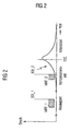
- FIG. 1 The diagram shows the pressure curve in a cylinder of a 4-stroke Otto internal combustion engine as a function of the crankshaft angle in ° KW.
- On the abscissa is also the intake stroke, the compression stroke and the power stroke entered.
- the Ausschiebetakt is omitted.
- the reference EOI_1 designates the end of the injection into the intake stroke
- the reference EOI_2 designates the end of the injection into the compression stroke.
- Top dead center is called TDC (Top Dead Center).
- the first fuel injection amount MFF_1 provides for a fuel vaporization at a correspondingly selected injection end EOI_1 while fresh air flows into the cylinder.
- the heat required for fuel evaporation is withdrawn from the incoming air, which is increased by increasing the charge density, the degree of delivery. If the total fuel quantity MFF is discontinued with the first injection, the highest delivery rate results.
- the split ratio between MFF_1 and MFF_2 can be adjusted to take advantage of both effects can be used and thus an optimization of maximum power and consumption result.
- the additional purge air increases the mass flow through the turbine, which at low speeds of the engine both the response (avoiding the so-called turbo lag), as well as the achievable full load can be increased.
- T e Air mass cylinder
- Total intake air mass M C y l M C y l + M S c a v
- the total intake air mass is composed of the air mass M Cyl , which remains in the cylinder and the scavenging air mass M Scav , ie the air mass that is flushed through the cylinder. From context (1) it follows that TE ⁇ 1. The larger the purge air mass M Scav , the smaller the value for TE. That is to say, the air mass meter 13 (FIG. 1) measures the total air mass which is sucked in overall, but which is then split via the trapping efficiency TE into an air mass which participates in the combustion and into an air mass which is flushed through the internal combustion engine.
- the lambda ⁇ Ex measured in the exhaust gas by means of the lambda probe 22 does not match the combustion lambda ⁇ Cyl due to the scavenging air mass M Scav not participating in the combustion.
- T e ⁇ ⁇ e x ⁇ Z y l
- the amount of fuel MFF_1 to be injected during the intake stroke is obtained by multiplying the total amount of fuel MFF by a distribution factor that is a function of the value of the air mass detected by the air mass meter 13 MAF_KGH and the engine speed N of the engine is read from a map KF.
- the amount of fuel MFF_2 to be injected during the compression stroke is obtained by subtracting the values for MFF and MFF_1.
- a typical split between the individual fuel quantities MFF_1 and MFF_2 is that 80% of the total fuel quantity MFF is injected into the intake stroke and 20% into the compression stroke.
- the value for the injection end time EOI_1 is read from a map KF1 depending on the value MAF__KGH, the engine speed N, and the fuel pressure FUP.
- the value for the injection end time EOI_2 is read from a map KF2 as a function of the value MFF_2, the engine speed N, the engine coolant temperature TCO and the fuel pressure FUP.
- This can be a three-dimensional map, or a combination of several individual maps.
- the air flow rate is increased according to the invention by means of flushing, the injection quantity setpoint values MFF_1 u. MFF_2 specified according to the set trapping efficiency TE.
- full-load range is understood to mean the range between the full load during suction operation, ie the max. Pressure that can be achieved with a pure naturally aspirated engine without charge (intake manifold pressure equal to ambient pressure, 1000 hpascal) and maximum full load, ie the pressure that can be achieved by means of charging (for example, 2000 hpascal).
- the fuel quantity MFF_1 to be injected during the intake stroke is dimensioned so that a stoichiometric Combustion lambda ⁇ Cyl yields.
- the amount of fuel to be injected during the compression stroke amount of fuel MFF_2 results from the requirement of a stoichiometric exhaust lambda ⁇ Ex .
- M F F _ 1 M F F * T e
- e O I _ 2 e O I _ 2 ( M F F _ 2 . N . T C O . F U P )
- the amount of fuel MFF_1 to be injected during the intake stroke is obtained by multiplying the total fuel amount MFF by the value for the trapping efficiency TE.
- the amount of fuel MFF_2 to be injected during the compression stroke is obtained by subtracting the values for MFF and MFF_1.
- knocking can occur, ie uncontrolled burns, for example, at hot spots of the combustion chamber.
- Combustion pressure fluctuations caused by knocking combustion are as a rule detected by structure-borne sound sensors mounted on the crankcase.
- knock signal KNKS which characterizes the knocking sound of a cylinder during a power stroke.
- KNKS Based on the knocking signal KNKS, a cylinder-individual moving average value is determined over all working cycles in knock-free combustion.
- This so-called noise value NL characterizes the engine noise level of a cylinder with non-knocking combustion.
- the known anti-knock control method correct as a function of exceeding the knock threshold THD by the knock signal KNKS the firing angle of the affected cylinder in the "direction late", whereby the knocking tendency is reduced. If no renewed knocking event occurs after an ignition angle correction on the knocking cylinder, the ignition angle intervention is reduced to zero via an integrator.
- the tendency to knock is reduced via a corresponding cylinder-specific distribution of the injection quantities MFF_1 Cyl_x and MFF_2 Cyl_x .
- the amount of fuel MFF_2 Cyl_x injected during the compression stroke is increased with a corresponding decrease in the amount of fuel MFF_1 Cyl_x injected into the intake stroke.
- the factor MFF_DEC_1 Cyl_x with which the cylinder-specific fuel quantity MFF_1 Cyl_x is reduced, is stored as a difference between the knock signal KNKS and the knock threshold THD_1 in a characteristic field KF3, depending on the air mass MAF_KGH, the engine speed N and the knock intensity KI.
- the cylinder-specific fuel quantity MFF_1 Cyl_x then results from the multiplication of the value for the fuel quantity MFF_1 to be injected during the intake stroke with the factor for the reduction read out from the characteristic map.
- the cylinder-specific fuel quantity MFF_2 Cyl_x is obtained by subtraction of the values for MFF and MFF_1 Cyl_x .
- the two threshold values THD_1, THD_2 are determined experimentally for the internal combustion engine and are stored in the memory device 24.
- the inventive method has been explained with reference to an internal combustion engine, which has a turbocharger as a charging device.
- the method is independent of the type of charging and is executable with any other charging device such as compressors, electric compressors or a combination of said devices. It only has to be suitable for generating a pressure on the intake side which is greater than the pressure on the exhaust gas side, so that rinsing is possible.
Landscapes
- Engineering & Computer Science (AREA)
- Chemical & Material Sciences (AREA)
- Combustion & Propulsion (AREA)
- Mechanical Engineering (AREA)
- General Engineering & Computer Science (AREA)
- Electrical Control Of Air Or Fuel Supplied To Internal-Combustion Engine (AREA)
- Output Control And Ontrol Of Special Type Engine (AREA)
Claims (11)
- Procédé de commande d'un moteur à combustion interne (10), dans lequel- l'air envoyé aux chambres de combustion du moteur à combustion interne (10) est suralimenté à l'aide d'un dispositif de suralimentation (25, 26),- au moyen d'un réglage d'arbre à came variable, on règle le chevauchement des soupapes d'échange de gaz du moteur à combustion interne,- la quantité de carburant injectée (MFF) nécessaire pour un fonctionnement homogène du moteur à combustion interne (10) est déterminée et est injectée directement dans les chambres de combustion du moteur à combustion interne (10),- la quantité de carburant injectée (MFF) est divisée en deux quantités partielles (MFF_1, MFF_2),- une première quantité partielle (MFF_1) est injectée dans la course d'admission et une deuxième quantité partielle (MFF_2) est injectée dans la course de compression,- le rapport de répartition entre les deux quantités partielles (MFF_1, MFF_2) est fixé en fonction du régime de charge du moteur à combustion interne (10)caractérisé en ce que- dans un fonctionnement du moteur à combustion interne (10) proche de la pleine charge, le chevauchement des soupapes est réglé de telle façon que l'air frais est balayé vers le côté échappement du moteur à combustion interne et le rapport de répartition des deux quantités partielles (MFF_1, MFF_2) est fixé par le rapport (TE) de la masse d'air (Mcyl) restante dans le cylindre du moteur à combustion interne (10) sur la masse d'air totale aspirée pendant un cycle de fonctionnement (Mcyl + MScav).
- Procédé selon la revendication 1, caractérisé en ce que la quantité de carburant (MFF_1) à injecter dans la course d'admission est obtenue par la multiplication de la quantité de carburant totale avec le rapport (TE) de la masse d'air aspirée dans un cycle de fonctionnement (Mcyl + Mscav) dans le cylindre du moteur à combustion interne (10).
- Procédé selon la revendication 1, caractérisé en ce que la quantité de carburant à injecter dans la course de compression (MFF_2) est obtenue par la différence des valeurs : quantité de carburant totale (MFF) et quantité de carburant à injecter dans une course d'admission (MFF_1).
- Procédé selon la revendication 1, caractérisé en ce qu'une valeur pour l'instant de fin d'injection (EOI_1) est fixée en fonction de la masse d'air (MAF_KGH), du nombre de tours (N) et de la pression de carburant (FUP).
- Procédé selon la revendication 1, caractérisé en ce que lors de l'apparition d'une combustion avec cliquetis dans un cylindre du moteur à combustion interne (10), le rapport de répartition entre les deux quantités partielles (MFF_1, MFF_2) est modifié individuellement par cylindre.
- Procédé selon la revendication 5, caractérisé en ce que la quantité de carburant (MFF_2Cyl_x) injectée dans la course de compression, est augmentée et la quantité de carburant (MFF_1Cyl_x) injectée dans la course d'admission est diminuée.
- Procédé selon la revendication 1, caractérisé en ce que l'air est suralimenté à l'aide d'un turbocompresseur à gaz d'échappement.
- Procédé selon la revendication 1, caractérisé en ce que l'air est suralimenté au moyen d'un surcompresseur qui est entraîné directement ou indirectement par le moteur à combustion interne.
- Procédé selon la revendication 1, caractérisé en ce que l'air est suralimenté au moyen d'un compresseur entraîné électriquement.
- Procédé selon la revendication 1, caractérisé en ce que le réglage de l'arbre à cames a lieu de façon continue.
- Procédé selon la revendication 1, caractérisé en ce que le réglage de l'arbre à cames a lieu par étapes.
Applications Claiming Priority (3)
| Application Number | Priority Date | Filing Date | Title |
|---|---|---|---|
| DE10256474A DE10256474B3 (de) | 2002-12-03 | 2002-12-03 | Verfahren zum Steuern einer mit Kraftstoffdirekteinspritzung arbeitenden Brennkraftmaschine |
| DE10256474 | 2002-12-03 | ||
| PCT/DE2003/003244 WO2004051067A1 (fr) | 2002-12-03 | 2003-09-29 | Procede pour commander un moteur a combustion interne a injection directe de carburant |
Publications (2)
| Publication Number | Publication Date |
|---|---|
| EP1567760A1 EP1567760A1 (fr) | 2005-08-31 |
| EP1567760B1 true EP1567760B1 (fr) | 2006-06-21 |
Family
ID=32115584
Family Applications (1)
| Application Number | Title | Priority Date | Filing Date |
|---|---|---|---|
| EP03753333A Expired - Lifetime EP1567760B1 (fr) | 2002-12-03 | 2003-09-29 | Procede pour commander un moteur a combustion interne a injection directe de carburant |
Country Status (4)
| Country | Link |
|---|---|
| US (1) | US7210449B2 (fr) |
| EP (1) | EP1567760B1 (fr) |
| DE (2) | DE10256474B3 (fr) |
| WO (1) | WO2004051067A1 (fr) |
Cited By (2)
| Publication number | Priority date | Publication date | Assignee | Title |
|---|---|---|---|---|
| DE102008003581B4 (de) * | 2008-01-09 | 2011-06-01 | Continental Automotive Gmbh | Verfahren und Vorrichtung zur Verringerung der Abgastemperatur bei einem Kraftfahrzeug |
| US11834983B2 (en) | 2019-07-15 | 2023-12-05 | The Research Foundation For The State University Of New York | Method for control of advanced combustion through split direct injection of high heat of vaporization fuel or water fuel mixtures |
Families Citing this family (18)
| Publication number | Priority date | Publication date | Assignee | Title |
|---|---|---|---|---|
| DE102004020458A1 (de) * | 2004-04-27 | 2005-11-24 | Adam Opel Ag | Betriebsverfahren für einen Ottomotor |
| DE102004030605B3 (de) * | 2004-06-24 | 2006-02-09 | Siemens Ag | Verfahren zur Steuerung einer Brennkraftmaschine mit einer Aufladevorrichtung |
| US7275516B1 (en) * | 2006-03-20 | 2007-10-02 | Ford Global Technologies, Llc | System and method for boosted direct injection engine |
| DE102006030213A1 (de) * | 2006-06-30 | 2008-01-03 | Fev Motorentechnik Gmbh | Homogenisiertes Einspritzverfahren |
| JP4253339B2 (ja) * | 2006-09-21 | 2009-04-08 | 株式会社日立製作所 | 内燃機関の制御装置 |
| US7866303B2 (en) * | 2007-02-15 | 2011-01-11 | Ford Global Technologies, Llc | Direct injection event-based engine starting |
| JP4479822B2 (ja) * | 2008-04-21 | 2010-06-09 | トヨタ自動車株式会社 | 筒内噴射式火花点火内燃機関 |
| WO2010085181A1 (fr) * | 2009-01-22 | 2010-07-29 | Volvo Lastvagnar Ab | Procédé et appareil d'actionnement variable de soupapes |
| DE102010036727B4 (de) | 2010-07-29 | 2022-06-15 | Dr. Ing. H.C. F. Porsche Aktiengesellschaft | Verfahren zum Betreiben einer aufgeladenen Brennkraftmaschine |
| US8608127B2 (en) | 2011-01-24 | 2013-12-17 | Fluke Corporation | Piezoelectric proportional control valve |
| US9399968B2 (en) * | 2013-09-05 | 2016-07-26 | Ford Global Technologies, Llc | Engine control for a liquid petroleum gas fueled engine |
| DE102013017799A1 (de) | 2013-10-25 | 2015-04-30 | GM Global Technology Operations LLC (n. d. Gesetzen des Staates Delaware) | Bestimmung des effektiven Kraftstoff-Luftverhältnisses einer aufgeladenen Verbrennungskraftmaschine mit Spülluftanteil |
| US9909488B2 (en) * | 2014-05-09 | 2018-03-06 | MAGNETI MARELLI S.p.A. | Method to determine the injection pattern in the intake stroke of the combustion cycle of the cylinders of a direct-injection internal combustion engine |
| GB2531298A (en) * | 2014-10-15 | 2016-04-20 | Gm Global Tech Operations Inc | Determination of the effective fuel-air ratio of a supercharged internal combustion engine with scavenging air component |
| EP3018325A1 (fr) * | 2014-11-04 | 2016-05-11 | Delphi Automotive Systems Luxembourg SA | Procédé amélioré de régulation de moteur pendant une récupération |
| US9404435B2 (en) * | 2014-12-01 | 2016-08-02 | Ford Global Technologies, Llc | Methods and systems for adjusting fuel injector operation |
| US10113453B2 (en) * | 2015-04-24 | 2018-10-30 | Randy Wayne McReynolds | Multi-fuel compression ignition engine |
| US10228206B2 (en) | 2016-10-11 | 2019-03-12 | Robert Gerard Bordley | Handgun safety device |
Family Cites Families (8)
| Publication number | Priority date | Publication date | Assignee | Title |
|---|---|---|---|---|
| JP2917617B2 (ja) * | 1991-10-28 | 1999-07-12 | トヨタ自動車株式会社 | 内燃機関 |
| DE19908729A1 (de) | 1999-03-01 | 2000-09-07 | Bosch Gmbh Robert | Kraftstoffeinspritzverfahren für eine Brennkraftmaschine |
| EP1052391B1 (fr) | 1999-05-12 | 2004-04-28 | Nissan Motor Co., Ltd. | Moteur à auto-allumage |
| JP3815163B2 (ja) * | 2000-01-25 | 2006-08-30 | 日産自動車株式会社 | 圧縮自己着火式内燃機関 |
| DE10065266A1 (de) | 2000-12-29 | 2002-07-18 | Bosch Gmbh Robert | Verfahren, Computerprogramm sowie Steuer- und/oder Regelgerät zum Betreiben einer Brennkraftmaschine und Brennkraftmaschine |
| JP2002206446A (ja) * | 2001-01-10 | 2002-07-26 | Hitachi Ltd | 内燃機関及び内燃機関の燃料噴射制御装置 |
| DE10140120A1 (de) * | 2001-08-16 | 2003-03-06 | Bosch Gmbh Robert | Verfahren und Vorrichtung zum Betreiben eines Verbrennungsmotors |
| DE10203750A1 (de) * | 2002-01-31 | 2003-03-27 | Porsche Ag | Verfahren zum Betreiben einer Viertakt-Brennkraftmaschine mit Direkteinspritzung |
-
2002
- 2002-12-03 DE DE10256474A patent/DE10256474B3/de not_active Expired - Fee Related
-
2003
- 2003-09-29 EP EP03753333A patent/EP1567760B1/fr not_active Expired - Lifetime
- 2003-09-29 US US10/537,603 patent/US7210449B2/en not_active Expired - Lifetime
- 2003-09-29 WO PCT/DE2003/003244 patent/WO2004051067A1/fr not_active Ceased
- 2003-09-29 DE DE50303994T patent/DE50303994D1/de not_active Expired - Lifetime
Cited By (2)
| Publication number | Priority date | Publication date | Assignee | Title |
|---|---|---|---|---|
| DE102008003581B4 (de) * | 2008-01-09 | 2011-06-01 | Continental Automotive Gmbh | Verfahren und Vorrichtung zur Verringerung der Abgastemperatur bei einem Kraftfahrzeug |
| US11834983B2 (en) | 2019-07-15 | 2023-12-05 | The Research Foundation For The State University Of New York | Method for control of advanced combustion through split direct injection of high heat of vaporization fuel or water fuel mixtures |
Also Published As
| Publication number | Publication date |
|---|---|
| DE50303994D1 (de) | 2006-08-03 |
| US20060278196A1 (en) | 2006-12-14 |
| US7210449B2 (en) | 2007-05-01 |
| WO2004051067A1 (fr) | 2004-06-17 |
| DE10256474B3 (de) | 2004-05-19 |
| EP1567760A1 (fr) | 2005-08-31 |
Similar Documents
| Publication | Publication Date | Title |
|---|---|---|
| EP1567760B1 (fr) | Procede pour commander un moteur a combustion interne a injection directe de carburant | |
| DE102008000012B4 (de) | Kraftmaschinensteuergerät | |
| EP1576268B1 (fr) | Procede pour chauffer un catalyseur d'un moteur a combustion interne a injection directe de carburant | |
| DE102007056216B4 (de) | Verfahren und Steuergerät zum beschleunigten Aufheizen eines Katalysators im Abgassystem eines aufgeladenen Verbrennungsmotors mit variabler Ventilsteuerung | |
| DE102011105110B4 (de) | Dieselmotor für ein Fahrzeug | |
| DE102011105907B4 (de) | Dieselmotor, Verfahren zum Steuern und Regeln des Dieselmotors und Computerprogrammprodukt | |
| DE112011101517B4 (de) | Steuerverfahren eines Fremdzündungsmotors und Fremdzündungsmotor | |
| DE102013202663B4 (de) | System und verfahren zum einspritzen von kraftstoff | |
| DE102018003865B4 (de) | Verbrennungsmotor, Steuer- bzw. Regelsystem dafür, Verfahren zum Steuern eines Motors und Computerprogrammprodukt | |
| DE102013001112B4 (de) | Steuervorrichtung eines Dieselmotors mit Turbolader, Dieselmotor, Verfahrenzum Steuern eines Dieselmotors und Computerprogrammprodukt | |
| DE102010062132B4 (de) | Verfahren zum Reduzieren der von einem Benzinmotor erzeugten Partikelmaterie | |
| DE102016010309B4 (de) | Direkteinspritzender Verbrennungsmotor, Steuervorrichtung für einen derartigen Motor, Verfahren zum Steuern eines Motors und Computerprogrammprodukt | |
| DE102018003645A1 (de) | Verfahren und Vorrichtung zum Steuern einer Kraftstoffeinspritzung eines Dieselmotors und Computerprogrammprodukt | |
| DE102013208047A1 (de) | Adaptive Regenerierung einer Abgasnachbehandlungseinrichtung in Ansprechen auf eine Biodiesel-Kraftstoffmischung | |
| DE102010029728B4 (de) | Verfahren zur Steuerung einer Einspritzung von Kraftstoff in einen Verbrennungsmotor, Steuergerät zum Steuern einer Einspritzung in einem Verbrennungsmotor sowie Verfahren zum Auswählen eines Einspritzventils für ein Motorsystem | |
| EP2923073B1 (fr) | Procédé de control d'un moteur à combustion à allumage commandé ayant un turbocompresseur | |
| DE102018003656B4 (de) | Verfahren und Vorrichtung zum Steuern einer Kraftstoffeinspritzung eines Dieselmotors und Computerprogrammprodukt | |
| DE102006035466B4 (de) | Selbstzündungsmaschinensteuergerät, das ein gewünschtes Ausgabemoment sicherstellt | |
| DE102018003647A1 (de) | Verfahren und Vorrichtung zum Steuern einer Kraftstoffeinspritzung eines Dieselmotors und Computerprogrammprodukt | |
| DE102018003646A1 (de) | Verfahren und Vorrichtung zum Steuern einer Kraftstoffeinspritzung eines Dieselmotors und Computerprogrammprodukt | |
| DE10303705B4 (de) | Verfahren zum Betreiben einer mit Kraftstoffdirekteinspritzung arbeitenden Brennkraftmaschine | |
| DE102015200047B4 (de) | Verfahren zum Betreiben einer Brennkraftmaschine mit Teilabschaltung | |
| DE102018200298B4 (de) | Fremdgezündete Brennkraftmaschine mit Teilabschaltung und Verfahren zum Betreiben einer derartigen Brennkraftmaschine | |
| EP0933519B1 (fr) | Moteur à combustion interne et procédé pour le fonctionnement compressé d'un moteur à combustion interne | |
| EP3101256B1 (fr) | Mode maigre au ralenti pour la réduction du nombre de particules |
Legal Events
| Date | Code | Title | Description |
|---|---|---|---|
| PUAI | Public reference made under article 153(3) epc to a published international application that has entered the european phase |
Free format text: ORIGINAL CODE: 0009012 |
|
| 17P | Request for examination filed |
Effective date: 20050517 |
|
| AK | Designated contracting states |
Kind code of ref document: A1 Designated state(s): AT BE BG CH CY CZ DE DK EE ES FI FR GB GR HU IE IT LI LU MC NL PT RO SE SI SK TR |
|
| GRAP | Despatch of communication of intention to grant a patent |
Free format text: ORIGINAL CODE: EPIDOSNIGR1 |
|
| RBV | Designated contracting states (corrected) |
Designated state(s): DE FR GB IT |
|
| RIN1 | Information on inventor provided before grant (corrected) |
Inventor name: ZHANG, HONG Inventor name: BEER, JOHANNES |
|
| GRAS | Grant fee paid |
Free format text: ORIGINAL CODE: EPIDOSNIGR3 |
|
| GRAA | (expected) grant |
Free format text: ORIGINAL CODE: 0009210 |
|
| AK | Designated contracting states |
Kind code of ref document: B1 Designated state(s): DE FR GB IT |
|
| REG | Reference to a national code |
Ref country code: GB Ref legal event code: FG4D Free format text: NOT ENGLISH |
|
| GBT | Gb: translation of ep patent filed (gb section 77(6)(a)/1977) |
Effective date: 20060712 |
|
| REF | Corresponds to: |
Ref document number: 50303994 Country of ref document: DE Date of ref document: 20060803 Kind code of ref document: P |
|
| ET | Fr: translation filed | ||
| PLBE | No opposition filed within time limit |
Free format text: ORIGINAL CODE: 0009261 |
|
| STAA | Information on the status of an ep patent application or granted ep patent |
Free format text: STATUS: NO OPPOSITION FILED WITHIN TIME LIMIT |
|
| 26N | No opposition filed |
Effective date: 20070322 |
|
| PGFP | Annual fee paid to national office [announced via postgrant information from national office to epo] |
Ref country code: FR Payment date: 20080912 Year of fee payment: 6 Ref country code: IT Payment date: 20080920 Year of fee payment: 6 |
|
| PGFP | Annual fee paid to national office [announced via postgrant information from national office to epo] |
Ref country code: GB Payment date: 20080918 Year of fee payment: 6 |
|
| GBPC | Gb: european patent ceased through non-payment of renewal fee |
Effective date: 20090929 |
|
| REG | Reference to a national code |
Ref country code: FR Ref legal event code: ST Effective date: 20100531 |
|
| PG25 | Lapsed in a contracting state [announced via postgrant information from national office to epo] |
Ref country code: FR Free format text: LAPSE BECAUSE OF NON-PAYMENT OF DUE FEES Effective date: 20090930 |
|
| PG25 | Lapsed in a contracting state [announced via postgrant information from national office to epo] |
Ref country code: GB Free format text: LAPSE BECAUSE OF NON-PAYMENT OF DUE FEES Effective date: 20090929 |
|
| PG25 | Lapsed in a contracting state [announced via postgrant information from national office to epo] |
Ref country code: IT Free format text: LAPSE BECAUSE OF NON-PAYMENT OF DUE FEES Effective date: 20090929 |
|
| PGFP | Annual fee paid to national office [announced via postgrant information from national office to epo] |
Ref country code: DE Payment date: 20190930 Year of fee payment: 17 |
|
| REG | Reference to a national code |
Ref country code: DE Ref legal event code: R084 Ref document number: 50303994 Country of ref document: DE |
|
| REG | Reference to a national code |
Ref country code: DE Ref legal event code: R081 Ref document number: 50303994 Country of ref document: DE Owner name: VITESCO TECHNOLOGIES GMBH, DE Free format text: FORMER OWNER: CONTINENTAL AUTOMOTIVE GMBH, 30165 HANNOVER, DE |
|
| REG | Reference to a national code |
Ref country code: DE Ref legal event code: R119 Ref document number: 50303994 Country of ref document: DE |
|
| PG25 | Lapsed in a contracting state [announced via postgrant information from national office to epo] |
Ref country code: DE Free format text: LAPSE BECAUSE OF NON-PAYMENT OF DUE FEES Effective date: 20210401 |
|
| REG | Reference to a national code |
Ref country code: DE Ref legal event code: R081 Ref document number: 50303994 Country of ref document: DE Owner name: VITESCO TECHNOLOGIES GMBH, DE Free format text: FORMER OWNER: VITESCO TECHNOLOGIES GMBH, 30165 HANNOVER, DE |