EP1568165B1 - Rekonfigurierbarer einfüge/abzweige multiplexer mit vergrabener dispersionskompensierungseinheit - Google Patents
Rekonfigurierbarer einfüge/abzweige multiplexer mit vergrabener dispersionskompensierungseinheit Download PDFInfo
- Publication number
- EP1568165B1 EP1568165B1 EP03776724A EP03776724A EP1568165B1 EP 1568165 B1 EP1568165 B1 EP 1568165B1 EP 03776724 A EP03776724 A EP 03776724A EP 03776724 A EP03776724 A EP 03776724A EP 1568165 B1 EP1568165 B1 EP 1568165B1
- Authority
- EP
- European Patent Office
- Prior art keywords
- oadm
- optical
- node
- dispersion
- wdm
- Prior art date
- Legal status (The legal status is an assumption and is not a legal conclusion. Google has not performed a legal analysis and makes no representation as to the accuracy of the status listed.)
- Expired - Lifetime
Links
- 230000003287 optical effect Effects 0.000 title claims abstract description 99
- 239000006185 dispersion Substances 0.000 title claims abstract description 72
- 238000000034 method Methods 0.000 claims abstract description 7
- 230000001902 propagating effect Effects 0.000 claims 1
- 230000003068 static effect Effects 0.000 abstract description 8
- 206010012812 Diffuse cutaneous mastocytosis Diseases 0.000 abstract 2
- 238000001541 differential confocal microscopy Methods 0.000 abstract 2
- 239000013307 optical fiber Substances 0.000 description 6
- 239000000835 fiber Substances 0.000 description 5
- 230000003044 adaptive effect Effects 0.000 description 4
- 238000010586 diagram Methods 0.000 description 4
- 230000008901 benefit Effects 0.000 description 2
- 230000005540 biological transmission Effects 0.000 description 2
- 230000003321 amplification Effects 0.000 description 1
- 239000000969 carrier Substances 0.000 description 1
- 230000001419 dependent effect Effects 0.000 description 1
- 230000001627 detrimental effect Effects 0.000 description 1
- 238000009434 installation Methods 0.000 description 1
- 238000007726 management method Methods 0.000 description 1
- 238000012986 modification Methods 0.000 description 1
- 230000004048 modification Effects 0.000 description 1
- 230000006855 networking Effects 0.000 description 1
- 238000003199 nucleic acid amplification method Methods 0.000 description 1
Images


Classifications
-
- H—ELECTRICITY
- H04—ELECTRIC COMMUNICATION TECHNIQUE
- H04J—MULTIPLEX COMMUNICATION
- H04J14/00—Optical multiplex systems
- H04J14/02—Wavelength-division multiplex systems
- H04J14/0201—Add-and-drop multiplexing
- H04J14/0202—Arrangements therefor
- H04J14/021—Reconfigurable arrangements, e.g. reconfigurable optical add/drop multiplexers [ROADM] or tunable optical add/drop multiplexers [TOADM]
-
- H—ELECTRICITY
- H04—ELECTRIC COMMUNICATION TECHNIQUE
- H04J—MULTIPLEX COMMUNICATION
- H04J14/00—Optical multiplex systems
- H04J14/02—Wavelength-division multiplex systems
- H04J14/0201—Add-and-drop multiplexing
- H04J14/0202—Arrangements therefor
- H04J14/0205—Select and combine arrangements, e.g. with an optical combiner at the output after adding or dropping
-
- H—ELECTRICITY
- H04—ELECTRIC COMMUNICATION TECHNIQUE
- H04J—MULTIPLEX COMMUNICATION
- H04J14/00—Optical multiplex systems
- H04J14/02—Wavelength-division multiplex systems
- H04J14/0201—Add-and-drop multiplexing
- H04J14/0202—Arrangements therefor
- H04J14/0206—Express channels arrangements
Definitions
- This invention relates generally to wavelength division multiplexed optical transport in telecommunications networks and in particular, to chromatic dispersion compensation.
- ROADMs reconfigurable optical add/drop multiplexers
- RROADMs remotely reconfigurable optical add/drop multiplexers
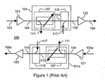
- Figure 1 illustrates a generic prior art RROADM based node 100 having two RROADMs 101 and 101a, wherein optical fibers 103 and 103a carry wavelength division multiplexed (WDM) optical signals from an adjacent node and optical fibers 105 and 105a carry the WDM signals around a network to the next adjacent node.
- WDM wavelength division multiplexed
- nodes are arranged in a ring configuration with a RROADM (101 and 101a) configured for each direction.
- Each generic RROADM implementation 101 and 101a includes an optical drop module 107 where one or more selected wavelengths of the WDM signal are received at input port 104 and diverted to drop port 111.
- the WDM optical signal containing the remaining wavelengths which have not been diverted, continue on through path 113 to add module 115 where one or more selected wavelengths from add port 117 are combined with the WDM optical signal on the through path and presented to output port 119.
- RROADM remotely reconfigurable OADM
- selection of wavelengths to add and drop can be controlled remotely.
- RROADM through losses and/or fiber losses are sufficient to require an ingress optical amplifier 121 at the RROADM input and an egress optical amplifier 123 at the RROADM output.
- DCMs dispersion compensation modules
- FIG. 2 illustrates a prior art RROADM implementation where dispersion compensation is required.
- the node 200 of Figure 2 uses RROADMs 101 and 101a of Figure 1 , with the addition of DCMs 201 and 203.
- DCM 201 provides dispersion compensation on the incoming span 103 (and 103a).
- DCM 203 provides dispersion compensation on the outgoing span 105 (and 105a).
- DCM 201 or DCM 203 or both are used depending on the amount of dispersion compensation required, the compensation values of the DCMs available and other network planning requirements.
- the optical losses in the DCMs require additional optical amplification as shown by associated optical amplifiers 205 and 207.
- the DCM 203 can be installed before the egress amplifier 123 and can obviate the need for additional amplifier 207. It is also possible to install DCM 201 between the ingress amplifier 121 and input port 104 although this can have a detrimental effect on optical signal-to-noise ratios (OSNR).
- OSNR optical signal-to-noise ratios
- Metro and regional networks have quite different dispersion issues compared to long haul networks.
- many spans may be too short to require individual span compensation but longer signal paths traversing multiple spans often exceed transponder dispersion limits. This problem becomes more noticeable when exploiting the ability to remotely reconfigure RROADMS to route wavelengths from any source to any destination, without exceeding total dispersion limits for the signal paths.
- Transponder dispersion limits have both positive and negative bounds (for example, -20 to +80 km, of equivalent SMF-28 fiber dispersion). It is therefore important not to overcompensate a signal path.
- Tuneable DCMs and adaptive dispersion compensation are much more costly than static DCMs.
- the corresponding channel is dispersion compensated and reflected to a drop port. Any remaining channels are circulated by the switches to the remaining dispersion compensating elements where they are dispersion compensated and reflected to an optical output.
- the node includes an insert port to allow multiplexing of additional channels. This allows the node to perform both drop and insert functions in addition to dispersion compensation and so forms a dispersion compensating drop and insert node.
- the present invention provides a RROADM with a buried dispersion compensation module (DCM), which provides dispersion compensation only to WDM signals, which pass through the RROADM.
- DCM dispersion compensation module
- a first aspect of the invention provides an optical add/drop multiplexer (OADM) having the features set out in claim 1 below.
- a second aspect of the invention provides an optical network having the features set out in claim 10 below.
- a third aspect of the invention provides a method of dispersion compensation set out in claim 13 below. Preferred features of the invention are set out in the dependent claims.
- an optical add/drop multiplexer has an input port, an output port, an optical through path, an optical drop module, and an optical add module and a dispersion compensation module.
- the input port is for receiving a wavelength division multiplexed (WDM) optical signal.
- the output port is for passing the WDM optical signal from the OADM.
- the optical through path is for carrying the WDM optical signal from the input port to the output port.
- the optical drop module is adapted to receive the WDM optical signal from the input port and to divert one or more wavelengths of the WDM optical signal to the drop port.
- the optical add module is for adding one or more wavelengths from the add port to the WDM optical signal at the output port.
- the dispersion compensation module is positioned in the optical through path between the drop module and the add module, and is adapted to compensate for dispersion in the WDM optical signal passing through the through path.
- the dispersion compensation module is adapted to compensate for variable chromatic dispersion.
- the dispersion compensation module is adapted to compensate for fixed chromatic dispersion.
- the OADM is a reconfigurable OADM.
- the OADM is a remotely reconfigurable OADM.
- the OADM is based on a broadcast and select architecture.
- the OADM is based on a wavelength blocker architecture.
- the OADM has east/west architecture.
- the OADM further comprises an optical amplifier at the input port.
- the OADM further comprises an optical amplifier at the output port.
- an optical network node having at least one OADM as described above.
- Another aspect of the present invention provides an optical network has at least one optical network node as described above.
- Some embodiments provide an optical network wherein alternate nodes have an OADM as described above.
- the network has short spans.
- the network is a metro network.
- Another example embodiment of the present invention is a method of dispersion compensation in an optical add/drop multiplexer (OADM) having an input port, an output port and an optical through path therebetween.
- the method has steps of receiving a wavelength division multiplexed (WDM) optical signal at the input port, diverting one or more wavelengths of the WDM optical signal to a drop port; performing dispersion compensation on the WDM optical signal remaining in the through path and adding one or more wavelengths from an add port to the WDM optical signal at the output port.
- WDM wavelength division multiplexed
- FIG. 1 is a diagram illustrating a prior art remotely reconfigurable optical add/drop multiplexer (RROADM) node
- FIG. 2 is a diagram illustrating a prior,art reconfigurable optical add/drop multiplexer (OADM) node with traditional span dispersion compensation;
- OADM optical add/drop multiplexer
- Figure 3 is a diagram illustrating a RROADM based node having buried DCMs in accordance with an embodiment of the invention.
- Figure 4 is a diagram illustrating part of an optical network showing a ROADM in accordance with an embodiment of the present invention.
- FIG. 3 illustrates a RROADM based node 300 having buried DCMs 303 in accordance with an embodiment of the invention.
- the node 300 has two RROADMs 301 and 301a similar to the RROADMs 101 and 101a of Figure 1 , with the exception of the DCMs buried inside the RROADMs.
- optical fibers 103 and 103a carry wavelength division multiplexed (WDM) optical signals from an adjacent node and optical fibers 105 and 105a carry the WDM optical signals around a network to the next adjacent node.
- An optical drop module 107 receives the WDM optical signal at input port 104 and diverts one or more selected wavelengths of the WDM signal to drop port 111.
- WDM wavelength division multiplexed
- DCM 303 applies dispersion compensation to these remaining wavelengths in the multiplexed optical signal and presents the compensated signal to add module 115 where one or more selected wavelengths from add port 117 are combined with the compensated WDM optical signal on the through path and presented to output port 119.
- RROADM remotely reconfigurable OADM
- selection of wavelengths to add and drop can be controlled remotely.
- This arrangement of the DCM permits the DCM to compensate optical signals passing through the node and not compensate dropped and added signals (the selected added/dropped wavelengths or channels) at the node. Thus, optical signals whose signal path is a single span between two nodes will not be compensated.
- DCMs can be selected from a limited set of standard values (e.g. 20, 40, 60, or 80 kilometers of compensation) and buried in only every second node.
- Typical RROADMs have an.optical amplifier 121 at the RROADM input and an optical amplifier 123 at the RROADM output. In many cases, these RROADMs can accommodate the buried DCMs 303 without the need for additional amplifiers.
- Figure 4 illustrates the use of buried compensation in part of an optical network 400 in accordance with an embodiment of the present invention.
- Network 400 has OADM nodes "A” 401, "B” 403, “C” 405 and “D” 407 connected via optical fibers.
- Node “B” 403 has a buried DCM 404 with a dispersion compensation of -40 km.
- Path 409 from Node A 401 to Node B 403 does not pass through DCM 404 and the dispersion of 26km is thus not compensated, but well within acceptable dispersion limits.
- path 411 from Node B 403 to Node C 405 has an uncompensated dispersion of 28 km and path 413 from Node C 405 to Node D 407 has an uncompensated dispersion of 30 km.
- Path 415 from Node A 401 to Node C 405 does pass through DCM 404 and thus the dispersion of 54 km is compensated by -40 km to produce an effective dispersion of 14km for the path.
- Path 417 from Node A 401 to Node D 407 also passes through DCM 404 and thus the dispersion of 84 km is compensated by -40 km to produce an effective dispersion of 44km for the path.
- This invention does not preclude the use of traditional span compensation and in fact combining buried compensation and span compensation can be useful when some spans in a metro network are much longer than others.
- the present invention is well suited for use with reconfigurable OADMs (ROADMs) and especially for use with remotely reconfigurable OADMs (RROADMs).
- ROADMs reconfigurable OADMs
- RROADMs remotely reconfigurable OADMs
- the invention can also be used with various other types of OADMs having a multiplexed through path. Examples of such OADMS include OADMs based on broadcast and select architectures using wavelength blockers.
- the present invention is well suited to use with static DCMs having standard compensation values, however, the invention can also be used with various other DCMs, such as tuneable and adaptive DCMs. This can be useful, for example, when an optical network evolves or is reconfigured and the original compensation values are no longer sufficient, static DCMs can be replaced with other DCMs or other types of DCMs.
Landscapes
- Engineering & Computer Science (AREA)
- Computer Networks & Wireless Communication (AREA)
- Signal Processing (AREA)
- Optical Communication System (AREA)
Claims (13)
- Optischer Add/Drop-Multiplexer (OADM) (301) mit einem eingebetteten Dispersionskompensationsmodul (303) für das Innere eines Knotens (300) in einem optischen Netzwerk, wobei der OADM (301) einen OADM-Eingangsport (104) zum Empfangen eines optischen Wellenlängenmultiplexsignals (WDM-Signals); einen OADM-Ausgangsport (119) zum Weiterleiten des optischen WDM-Signals von dem OADM (301); einen optischen Durchgangspfad (113) zum Befördern des optischen WDM-Signals von dem OADM-Eingangsport (104) zu dem OADM-Ausgangsport (119) in dem Knoten; ein optisches Drop-Modul (107) zum Empfangen des optischen WDM-Signals von dem OADM-Eingangsport (104) und zum Umleiten einer oder mehrerer Wellenlängen des optischen WDM-Signals zu einem OADM-Drop-Port (111) umfasst;
dadurch gekennzeichnet, dass der OADM (301) umfasst:(a) ein optisches Add-Modul (115) zum Hinzufügen einer oder mehrerer Wellenlängen von einem OADM-Add-Port (117) zu dem optischen WDM-Signal am OADM-Ausgangsport (119); und(b) das Dispersionskompensationsmodul (303), das in dem optischen Durchgangspfad (113) zwischen dem optischen Drop-Modul (107) und dem optischen Add-Modul (115) positioniert ist und geeignet ist, um nur eine Dispersion in dem optischen WDM-Signal zu kompensieren, das durch den Durchgangspfad (113) in dem Knoten (300) gelangt. - OADM nach Anspruch 1,
wobei das Dispersionskompensationsmodul geeignet ist, um eine chromatische Dispersion zu kompensieren. - OADM nach Anspruch 1,
wobei das Dispersionskompensationsmodul geeignet ist, um eine Dispersion mit einem festen Wert zu kompensieren. - OADM nach Anspruch 1,
wobei der OADM ein rekonfigurierbarer OADM (ROADM) ist. - OADM nach Anspruch 4,
wobei der OADM ein aus der Ferne rekonfigurierbarer OADM (RROADM) ist. - OADM nach Anspruch 1,
wobei der OADM ferner einen optischen Verstärker am Eingangsport umfasst. - OADM nach Anspruch 9,
wobei der OADM ferner einen optischen Verstärker am Ausgangsport umfasst. - Knoten eines optischen Netzwerks mit zumindest einem OADM nach Anspruch 1.
- Optisches Netzwerk mit zumindest einem Knoten eines optischen Netzwerks nach Anspruch 8.
- Optisches Netzwerk, wobei wechselnde Knoten den OADM nach Anspruch 1 umfassen.
- Optisches Netzwerk nach Anspruch 10,
wobei das Netzwerk kurze Spannen aufweist. - Optisches Netzwerk nach Anspruch 10,
wobei das Netzwerk ein Metronetzwerk ist. - Verfahren zur Dispersionskompensation in einem optischen Add/Drop-Multiplexer (OADM) (301) in einem Knoten (300) in einem optischen Netzwerk, wobei der OADM (301) einen Eingangsport (104), einen Ausgangsport (119) und einen optischen Durchgangspfad (113) dazwischen aufweist, umfassend, dass ein optisches Wellenlängenmultiplexsignal (WDM-Signal) an dem Eingangsport (104) empfangen wird und eine oder mehrere Wellenlängen des optischen WDM-Signals zu einem Drop-Port (111) umgeleitet werden;
wobei das Verfahren dadurch gekennzeichnet ist, dass:(a) eine Dispersion (303) nur für einen Teil des optischen WDM-Signals in dem Knoten (300) kompensiert wird, der in dem Durchgangspfad (113) in dem Knoten (300) verbleibt; und(b) am Ausgangsport (119) eine oder mehrere Wellenlängen von einem Add-Port (117) zu dem dispersionskompensierten Teil des optischen WDM-Signals hinzugefügt werden, das sich an dem Durchgangspfad (113) ausbreitet.
Applications Claiming Priority (3)
| Application Number | Priority Date | Filing Date | Title |
|---|---|---|---|
| US42796002P | 2002-11-21 | 2002-11-21 | |
| US427960P | 2002-11-21 | ||
| PCT/CA2003/001828 WO2004047349A1 (en) | 2002-11-21 | 2003-11-14 | Reconfigurable optical add/drop multiplexer with buried dispersion compensation module |
Publications (2)
| Publication Number | Publication Date |
|---|---|
| EP1568165A1 EP1568165A1 (de) | 2005-08-31 |
| EP1568165B1 true EP1568165B1 (de) | 2012-01-04 |
Family
ID=32326619
Family Applications (1)
| Application Number | Title | Priority Date | Filing Date |
|---|---|---|---|
| EP03776724A Expired - Lifetime EP1568165B1 (de) | 2002-11-21 | 2003-11-14 | Rekonfigurierbarer einfüge/abzweige multiplexer mit vergrabener dispersionskompensierungseinheit |
Country Status (5)
| Country | Link |
|---|---|
| US (1) | US6931176B2 (de) |
| EP (1) | EP1568165B1 (de) |
| AU (1) | AU2003286050B2 (de) |
| CA (1) | CA2444078A1 (de) |
| WO (1) | WO2004047349A1 (de) |
Families Citing this family (8)
| Publication number | Priority date | Publication date | Assignee | Title |
|---|---|---|---|---|
| JP4576094B2 (ja) * | 2003-03-03 | 2010-11-04 | 富士通株式会社 | 波長多重光中継伝送方法および中継装置 |
| WO2004114530A2 (en) * | 2003-06-20 | 2004-12-29 | Corvis Corporation | Systems, devices, and methods for controlling non-linear optical interactions |
| US7184666B1 (en) * | 2003-10-01 | 2007-02-27 | Ciena Corporation | Reconfigurable optical add-drop multiplexer |
| US7672595B1 (en) * | 2003-12-23 | 2010-03-02 | Nortel Networks Limited | Optical transmission system architecture supporting migration to electronic compensation of link impairments |
| US7447401B2 (en) | 2005-02-28 | 2008-11-04 | Optium Australia Pty Limited | Optical communications system |
| JP4733499B2 (ja) * | 2005-10-31 | 2011-07-27 | 株式会社日立ハイテクインスツルメンツ | 電子部品装着装置 |
| US8160453B1 (en) * | 2006-03-30 | 2012-04-17 | Rockstar Bidco, LP | Protection switching with transmitter compensation function |
| JP5644446B2 (ja) * | 2010-12-06 | 2014-12-24 | 富士通株式会社 | 光伝送装置 |
Family Cites Families (5)
| Publication number | Priority date | Publication date | Assignee | Title |
|---|---|---|---|---|
| JP3977430B2 (ja) | 1996-03-29 | 2007-09-19 | ブリティッシュ・テレコミュニケーションズ・パブリック・リミテッド・カンパニー | 色分散補償用ノード |
| US5905838A (en) * | 1998-02-18 | 1999-05-18 | Lucent Technologies Inc. | Dual window WDM optical fiber communication |
| US6370300B1 (en) * | 1999-02-18 | 2002-04-09 | Lucent Technologies Inc. | Optical communication system incorporating automatic dispersion compensation modules |
| US6445850B1 (en) * | 2000-08-11 | 2002-09-03 | Sycamore Networks, Inc. | Method and apparatus for per-band compensation with gap-free band structure for high speed DWDM transmission |
| GB0119154D0 (en) * | 2001-08-06 | 2001-09-26 | Southampton Photonics Ltd | An optical demultiplexer |
-
2003
- 2003-08-08 US US10/636,664 patent/US6931176B2/en not_active Expired - Fee Related
- 2003-10-09 CA CA002444078A patent/CA2444078A1/en not_active Abandoned
- 2003-11-14 AU AU2003286050A patent/AU2003286050B2/en not_active Ceased
- 2003-11-14 EP EP03776724A patent/EP1568165B1/de not_active Expired - Lifetime
- 2003-11-14 WO PCT/CA2003/001828 patent/WO2004047349A1/en not_active Ceased
Also Published As
| Publication number | Publication date |
|---|---|
| WO2004047349A1 (en) | 2004-06-03 |
| AU2003286050A1 (en) | 2004-06-15 |
| US20040101236A1 (en) | 2004-05-27 |
| US6931176B2 (en) | 2005-08-16 |
| AU2003286050B2 (en) | 2006-11-02 |
| EP1568165A1 (de) | 2005-08-31 |
| CA2444078A1 (en) | 2004-05-21 |
Similar Documents
| Publication | Publication Date | Title |
|---|---|---|
| US6947670B1 (en) | Optical add/drop arrangement for ring networks employing wavelength division multiplexing | |
| US6486988B1 (en) | Upgrading optical communications systems without traffic interruption | |
| US7321729B2 (en) | Optical ring network with selective signal regeneration and wavelength conversion | |
| US8396361B2 (en) | Method for the protection of a passive optical transmission network as well as a passive optical transmission network with a corresponding protection mechanism | |
| US7184663B2 (en) | Optical ring network with hub node and method | |
| US7483637B2 (en) | Optical ring network with optical subnets and method | |
| US7283740B2 (en) | Optical ring network with optical subnets and method | |
| US6452703B1 (en) | Optical add-drop multiplexing technique and wavelength division multiplexing optical link using such a multiplexing technique | |
| US6950609B2 (en) | Tunable, multi-port optical add-drop multiplexer | |
| EP2339771A2 (de) | Optisches Ringnetzwerk mit Knoten und Verfahren | |
| US7519296B2 (en) | Optical demultiplexing method and optical multiplexing method, and optical transmission apparatus using same | |
| EP1568165B1 (de) | Rekonfigurierbarer einfüge/abzweige multiplexer mit vergrabener dispersionskompensierungseinheit | |
| US6674935B2 (en) | Optical connection arrangements | |
| US20050002671A1 (en) | Wavelength division multiplexed optical transmission systems, apparatuses, and methods | |
| US7110638B2 (en) | Reconfigurable optical node with distributed spectral filtering | |
| US20050196169A1 (en) | System and method for communicating traffic between optical rings | |
| US7283739B2 (en) | Multiple subnets in an optical ring network and method | |
| US7603035B2 (en) | Method and system for a data centric architecture in an optical network | |
| US7715711B2 (en) | Wavelength selective switch design configurations for mesh light-trails | |
| CA2350864C (en) | Optical connection arrangements |
Legal Events
| Date | Code | Title | Description |
|---|---|---|---|
| PUAI | Public reference made under article 153(3) epc to a published international application that has entered the european phase |
Free format text: ORIGINAL CODE: 0009012 |
|
| 17P | Request for examination filed |
Effective date: 20050617 |
|
| AK | Designated contracting states |
Kind code of ref document: A1 Designated state(s): AT BE BG CH CY CZ DE DK EE ES FI FR GB GR HU IE IT LI LU MC NL PT RO SE SI SK TR |
|
| AX | Request for extension of the european patent |
Extension state: AL LT LV MK |
|
| DAX | Request for extension of the european patent (deleted) | ||
| RBV | Designated contracting states (corrected) |
Designated state(s): DE FR GB IT |
|
| 17Q | First examination report despatched |
Effective date: 20090608 |
|
| GRAP | Despatch of communication of intention to grant a patent |
Free format text: ORIGINAL CODE: EPIDOSNIGR1 |
|
| GRAJ | Information related to disapproval of communication of intention to grant by the applicant or resumption of examination proceedings by the epo deleted |
Free format text: ORIGINAL CODE: EPIDOSDIGR1 |
|
| GRAP | Despatch of communication of intention to grant a patent |
Free format text: ORIGINAL CODE: EPIDOSNIGR1 |
|
| RAP1 | Party data changed (applicant data changed or rights of an application transferred) |
Owner name: ALCATEL-LUCENT CANADA INC. |
|
| GRAS | Grant fee paid |
Free format text: ORIGINAL CODE: EPIDOSNIGR3 |
|
| GRAA | (expected) grant |
Free format text: ORIGINAL CODE: 0009210 |
|
| AK | Designated contracting states |
Kind code of ref document: B1 Designated state(s): DE FR GB IT |
|
| REG | Reference to a national code |
Ref country code: GB Ref legal event code: FG4D |
|
| REG | Reference to a national code |
Ref country code: DE Ref legal event code: R096 Ref document number: 60339619 Country of ref document: DE Effective date: 20120308 |
|
| PLBE | No opposition filed within time limit |
Free format text: ORIGINAL CODE: 0009261 |
|
| STAA | Information on the status of an ep patent application or granted ep patent |
Free format text: STATUS: NO OPPOSITION FILED WITHIN TIME LIMIT |
|
| 26N | No opposition filed |
Effective date: 20121005 |
|
| REG | Reference to a national code |
Ref country code: DE Ref legal event code: R097 Ref document number: 60339619 Country of ref document: DE Effective date: 20121005 |
|
| REG | Reference to a national code |
Ref country code: FR Ref legal event code: GC Effective date: 20130611 |
|
| REG | Reference to a national code |
Ref country code: GB Ref legal event code: 732E Free format text: REGISTERED BETWEEN 20130808 AND 20130814 |
|
| REG | Reference to a national code |
Ref country code: FR Ref legal event code: RG Effective date: 20141015 |
|
| REG | Reference to a national code |
Ref country code: FR Ref legal event code: PLFP Year of fee payment: 13 |
|
| REG | Reference to a national code |
Ref country code: FR Ref legal event code: PLFP Year of fee payment: 14 |
|
| REG | Reference to a national code |
Ref country code: FR Ref legal event code: PLFP Year of fee payment: 15 |
|
| PGFP | Annual fee paid to national office [announced via postgrant information from national office to epo] |
Ref country code: FR Payment date: 20171127 Year of fee payment: 15 Ref country code: DE Payment date: 20171129 Year of fee payment: 15 |
|
| PGFP | Annual fee paid to national office [announced via postgrant information from national office to epo] |
Ref country code: GB Payment date: 20171127 Year of fee payment: 15 |
|
| PGFP | Annual fee paid to national office [announced via postgrant information from national office to epo] |
Ref country code: IT Payment date: 20171221 Year of fee payment: 15 |
|
| REG | Reference to a national code |
Ref country code: DE Ref legal event code: R119 Ref document number: 60339619 Country of ref document: DE |
|
| GBPC | Gb: european patent ceased through non-payment of renewal fee |
Effective date: 20181114 |
|
| PG25 | Lapsed in a contracting state [announced via postgrant information from national office to epo] |
Ref country code: FR Free format text: LAPSE BECAUSE OF NON-PAYMENT OF DUE FEES Effective date: 20181130 Ref country code: DE Free format text: LAPSE BECAUSE OF NON-PAYMENT OF DUE FEES Effective date: 20190601 Ref country code: IT Free format text: LAPSE BECAUSE OF NON-PAYMENT OF DUE FEES Effective date: 20181114 |
|
| PG25 | Lapsed in a contracting state [announced via postgrant information from national office to epo] |
Ref country code: GB Free format text: LAPSE BECAUSE OF NON-PAYMENT OF DUE FEES Effective date: 20181114 |
|
| REG | Reference to a national code |
Ref country code: DE Ref legal event code: R082 Ref document number: 60339619 Country of ref document: DE Representative=s name: BARKHOFF REIMANN VOSSIUS, DE Ref country code: DE Ref legal event code: R081 Ref document number: 60339619 Country of ref document: DE Owner name: WSOU INVESTMENTS, LLC, LOS ANGELES, US Free format text: FORMER OWNER: ALCATEL-LUCENT CANADA INC., OTTAWA, ONTARIO, CA |
|
| REG | Reference to a national code |
Ref country code: GB Ref legal event code: 732E Free format text: REGISTERED BETWEEN 20200924 AND 20200930 |