EP1568572A2 - Procédure de commande de direction véhicule avec vérification de plausibilité de signal - Google Patents
Procédure de commande de direction véhicule avec vérification de plausibilité de signal Download PDFInfo
- Publication number
- EP1568572A2 EP1568572A2 EP05001643A EP05001643A EP1568572A2 EP 1568572 A2 EP1568572 A2 EP 1568572A2 EP 05001643 A EP05001643 A EP 05001643A EP 05001643 A EP05001643 A EP 05001643A EP 1568572 A2 EP1568572 A2 EP 1568572A2
- Authority
- EP
- European Patent Office
- Prior art keywords
- layer
- steering
- safety
- steering system
- signal
- Prior art date
- Legal status (The legal status is an assumption and is not a legal conclusion. Google has not performed a legal analysis and makes no representation as to the accuracy of the status listed.)
- Withdrawn
Links
Images

Classifications
-
- B—PERFORMING OPERATIONS; TRANSPORTING
- B62—LAND VEHICLES FOR TRAVELLING OTHERWISE THAN ON RAILS
- B62D—MOTOR VEHICLES; TRAILERS
- B62D6/00—Arrangements for automatically controlling steering depending on driving conditions sensed and responded to, e.g. control circuits
- B62D6/002—Arrangements for automatically controlling steering depending on driving conditions sensed and responded to, e.g. control circuits computing target steering angles for front or rear wheels
- B62D6/003—Arrangements for automatically controlling steering depending on driving conditions sensed and responded to, e.g. control circuits computing target steering angles for front or rear wheels in order to control vehicle yaw movement, i.e. around a vertical axis
-
- B—PERFORMING OPERATIONS; TRANSPORTING
- B60—VEHICLES IN GENERAL
- B60T—VEHICLE BRAKE CONTROL SYSTEMS OR PARTS THEREOF; BRAKE CONTROL SYSTEMS OR PARTS THEREOF, IN GENERAL; ARRANGEMENT OF BRAKING ELEMENTS ON VEHICLES IN GENERAL; PORTABLE DEVICES FOR PREVENTING UNWANTED MOVEMENT OF VEHICLES; VEHICLE MODIFICATIONS TO FACILITATE COOLING OF BRAKES
- B60T8/00—Arrangements for adjusting wheel-braking force to meet varying vehicular or ground-surface conditions, e.g. limiting or varying distribution of braking force
- B60T8/32—Arrangements for adjusting wheel-braking force to meet varying vehicular or ground-surface conditions, e.g. limiting or varying distribution of braking force responsive to a speed condition, e.g. acceleration or deceleration
- B60T8/88—Arrangements for adjusting wheel-braking force to meet varying vehicular or ground-surface conditions, e.g. limiting or varying distribution of braking force responsive to a speed condition, e.g. acceleration or deceleration with failure responsive means, i.e. means for detecting and indicating faulty operation of the speed responsive control means
- B60T8/885—Arrangements for adjusting wheel-braking force to meet varying vehicular or ground-surface conditions, e.g. limiting or varying distribution of braking force responsive to a speed condition, e.g. acceleration or deceleration with failure responsive means, i.e. means for detecting and indicating faulty operation of the speed responsive control means using electrical circuitry
-
- B—PERFORMING OPERATIONS; TRANSPORTING
- B62—LAND VEHICLES FOR TRAVELLING OTHERWISE THAN ON RAILS
- B62D—MOTOR VEHICLES; TRAILERS
- B62D5/00—Power-assisted or power-driven steering
- B62D5/008—Changing the transfer ratio between the steering wheel and the steering gear by variable supply of energy, e.g. by using a superposition gear
-
- B—PERFORMING OPERATIONS; TRANSPORTING
- B62—LAND VEHICLES FOR TRAVELLING OTHERWISE THAN ON RAILS
- B62D—MOTOR VEHICLES; TRAILERS
- B62D5/00—Power-assisted or power-driven steering
- B62D5/04—Power-assisted or power-driven steering electrical, e.g. using an electric servo-motor connected to, or forming part of, the steering gear
- B62D5/0457—Power-assisted or power-driven steering electrical, e.g. using an electric servo-motor connected to, or forming part of, the steering gear characterised by control features of the drive means as such
- B62D5/046—Controlling the motor
- B62D5/0463—Controlling the motor calculating assisting torque from the motor based on driver input
-
- B—PERFORMING OPERATIONS; TRANSPORTING
- B62—LAND VEHICLES FOR TRAVELLING OTHERWISE THAN ON RAILS
- B62D—MOTOR VEHICLES; TRAILERS
- B62D5/00—Power-assisted or power-driven steering
- B62D5/04—Power-assisted or power-driven steering electrical, e.g. using an electric servo-motor connected to, or forming part of, the steering gear
- B62D5/0457—Power-assisted or power-driven steering electrical, e.g. using an electric servo-motor connected to, or forming part of, the steering gear characterised by control features of the drive means as such
- B62D5/0481—Power-assisted or power-driven steering electrical, e.g. using an electric servo-motor connected to, or forming part of, the steering gear characterised by control features of the drive means as such monitoring the steering system, e.g. failures
- B62D5/049—Power-assisted or power-driven steering electrical, e.g. using an electric servo-motor connected to, or forming part of, the steering gear characterised by control features of the drive means as such monitoring the steering system, e.g. failures detecting sensor failures
-
- B—PERFORMING OPERATIONS; TRANSPORTING
- B62—LAND VEHICLES FOR TRAVELLING OTHERWISE THAN ON RAILS
- B62D—MOTOR VEHICLES; TRAILERS
- B62D5/00—Power-assisted or power-driven steering
- B62D5/04—Power-assisted or power-driven steering electrical, e.g. using an electric servo-motor connected to, or forming part of, the steering gear
- B62D5/0457—Power-assisted or power-driven steering electrical, e.g. using an electric servo-motor connected to, or forming part of, the steering gear characterised by control features of the drive means as such
- B62D5/0481—Power-assisted or power-driven steering electrical, e.g. using an electric servo-motor connected to, or forming part of, the steering gear characterised by control features of the drive means as such monitoring the steering system, e.g. failures
- B62D5/0493—Power-assisted or power-driven steering electrical, e.g. using an electric servo-motor connected to, or forming part of, the steering gear characterised by control features of the drive means as such monitoring the steering system, e.g. failures detecting processor errors, e.g. plausibility of steering direction
-
- B—PERFORMING OPERATIONS; TRANSPORTING
- B62—LAND VEHICLES FOR TRAVELLING OTHERWISE THAN ON RAILS
- B62D—MOTOR VEHICLES; TRAILERS
- B62D6/00—Arrangements for automatically controlling steering depending on driving conditions sensed and responded to, e.g. control circuits
- B62D6/002—Arrangements for automatically controlling steering depending on driving conditions sensed and responded to, e.g. control circuits computing target steering angles for front or rear wheels
-
- B—PERFORMING OPERATIONS; TRANSPORTING
- B60—VEHICLES IN GENERAL
- B60T—VEHICLE BRAKE CONTROL SYSTEMS OR PARTS THEREOF; BRAKE CONTROL SYSTEMS OR PARTS THEREOF, IN GENERAL; ARRANGEMENT OF BRAKING ELEMENTS ON VEHICLES IN GENERAL; PORTABLE DEVICES FOR PREVENTING UNWANTED MOVEMENT OF VEHICLES; VEHICLE MODIFICATIONS TO FACILITATE COOLING OF BRAKES
- B60T2260/00—Interaction of vehicle brake system with other systems
- B60T2260/02—Active Steering, Steer-by-Wire
-
- B—PERFORMING OPERATIONS; TRANSPORTING
- B60—VEHICLES IN GENERAL
- B60T—VEHICLE BRAKE CONTROL SYSTEMS OR PARTS THEREOF; BRAKE CONTROL SYSTEMS OR PARTS THEREOF, IN GENERAL; ARRANGEMENT OF BRAKING ELEMENTS ON VEHICLES IN GENERAL; PORTABLE DEVICES FOR PREVENTING UNWANTED MOVEMENT OF VEHICLES; VEHICLE MODIFICATIONS TO FACILITATE COOLING OF BRAKES
- B60T2270/00—Further aspects of brake control systems not otherwise provided for
- B60T2270/40—Failsafe aspects of brake control systems
- B60T2270/404—Brake-by-wire or X-by-wire failsafe
Definitions
- the invention relates to a method for operating a Steering system according to the preamble of claim 1.
- a generic method is known from DE 197 51 125 A1 known. These are the driver by a Steering wheel applied steering movements, by a Sensor detected steering wheel angle, by means of a superposition gear with the movements of the actuator, the motor angle, superimposed. The resulting superimposed Movement is via the steering gear or the Steering linkage to steerable wheels for adjustment the steering angle forwarded.
- the actuator designed as an electric motor.
- the functional principle or the applications of such Servolenksystems consist in particular that the Steering through the translation of the superposition gear can be carried out indirectly and thus low Steering wheel torques can be achieved. As a result, Very large steering wheel angles are avoided by suitable motor angles are superimposed, so with Steering wheel angles usual size required output angle can be adjusted.
- the steering assistance required motor angle or its setpoint is determined from the steering wheel angle. Furthermore the motor angle can also be dependent on signals, which by sensors and / or others Vehicle systems, such as an electronic stability program (ESP), represent recorded vehicle movements. This is done by a control unit, on which for the determination of the required motor angle or for the control of the Nutzanprocessen required programs are executed.
- Vehicle speed, Pinion angle, the motor angle itself and the Steering wheel angle required by the control unit are e.g. Vehicle speed, Pinion angle, the motor angle itself and the Steering wheel angle required by the control unit.
- the present invention is therefore based on the object a method for operating a steering system, to create the type mentioned, which the Disadvantages of the prior art avoids, in particular a high diagnostic quality of the safety functions in the plausibility of the Nutzzeingangssignale provides.
- the inventive method for operating a steering system in an advantageous Way extended to a security surveillance process which the plausibility of the input signals of the controller by means of suitable electronics dependent and application-related safety functions and due to the monitoring the payloads (e.g., a variable steering ratio).
- a high diagnostic grade is provided by the provision additional virtual channels for plausibility of safety-critical input signals created.
- the signals are thereby advantageously first with a communication test to the source, a sensor diagnosis and an area and gradient check Mistake.
- the application - related Safety features especially the safety critical Input signals through at least one monitor another virtual signal, the virtual Signal model-based over other independent Input signals is calculated.
- the pinion angle can be based on wheel speeds, in particular checked by front wheel speeds of the motor vehicle become.
- the motor angle can with the help of the pinion angle and of the steering wheel angle via a forced relationship of the three Angle can be monitored under the steering system. Furthermore there is the possibility of the motor angle based the motor currents and voltages or based on the Make the motor currents and a load model plausible.
- the steering wheel angle can by means of the motor angle and the pinion angle on the forced relationship of three angles within the framework of the steering system plausibility become.
- the vehicle speed may be based on wheel speeds, in particular of rear wheel speeds of Motor vehicle monitored. It is advantageous to take into account any intervention by an ESP.
- the Security monitoring procedure in several shifts is divided, which the input signals of the control unit check for plausibility and based on the states the input signals the useful applications of the Configure the steering system.
- a Layer formed as an application monitoring layer is what application-related security features performs.
- a layer as a signal layer is formed, which a signal status of the steering system, the signal layer to as input the results of the E / E / PES monitoring layer and the application monitoring layer receives.
- the signal layer receives in an advantageous manner via defined interfaces the results of the E / E / PES monitoring layer and the application monitoring layer and thereby the signal status of the Define the steering system and this to the parent Pass on layers. From an exchange of security features in the lower layers is the signal layer not affected.
- a layer as a system status layer is formed, which is a system status determined by the steering system, wherein the system status layer as input the results of the signal layer and the application monitoring layer.
- a layer is used as an application configuration layer is formed, which the User applications due to the system health layer calculated system status of the steering system and / or the results of the signal layer.
- an overall status of the steering system can be determined and the payloads are switched accordingly. For example, if there is no reliable data in terms of the speed of the motor vehicle exist, must have suitable substitute modes for the variable Steering translation to be switched. In particular at higher speeds too direct steering ratio can be dangerous (for example, highway driving).
- the invention is based on an embodiment being represented. This is exemplary from an aforementioned overlay steering went out.
- the invention is self-evident also with other steering systems, such as Steer by Wire, etc., can be used.
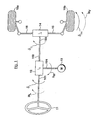
- Fig. 1 and Fig. 2 shows with the reference numerals 11 and 21 an operable by the driver of the vehicle steering wheel.
- a superposition gear 12 and 22 via a connection 101 a steering wheel angle ⁇ S is supplied.
- the superposition gear 12 and 22 via a connection 104 a motor angle ⁇ M of an actuator 13 and 23 fed, the actuator may be designed as an electric motor.
- a superimposed movement or a pinion angle ⁇ G via a connection 102, 103 a steering gear 14 and 24, which in turn via a steering linkage 16 according to the superimposed motion or the total angle ⁇ G steerable wheels 15a and 15b is applied with a steering angle ⁇ Fm .
- the steerable wheels 15a and 15b are acted upon by a reaction moment MV influenced by the road.
- Sensors 26 and 28 are also shown in FIG. 2, wherein the sensor 28 detects the steering wheel angle ⁇ S and supplies it to a control unit 27, while the reference numeral 26 identifies sensors which detect movements 25 of the vehicle (for example yawing, lateral acceleration, wheel speeds , Vehicle speed, etc.) and the pinion angle ⁇ G detect and supply corresponding signals to the control unit 27.
- the controller 27 determines, depending on the detected steering wheel angle ⁇ S and possibly depending on the vehicle movements 25 a manipulated variable u to control the actuator 13 and 23 for the realization of useful applications (eg variable steering ratio - see Fig. 4 and 5).
- the signals of the sensors 26 can also be taken from a CAN bus system of the vehicle.
- a power steering function is achieved by the steering system shown in FIGS. 1 and 2 in that by a large overall ratio (i L * i Ü ), ie by a very indirect steering, the steering wheel torque M L is reduced.
- the steering wheel angle ⁇ S is superimposed on a motor angle ⁇ M according to the above equation 1, so that a desired front wheel angle ⁇ Fm can be adjusted with a not too large steering wheel angle. It can be realized by a suitable control of the engine relationships between the steering wheel angle and the steering angle, which can also depend on the driving condition, such as the vehicle speed or the steering wheel angle.
- the steering wheel torque M L is dependent on the reaction torque M V at the steerable wheels. This results in the already mentioned problem that can not be achieved for all driving conditions acceptable steering wheel torque or steering feel by choosing a constant ratio of the steering gear.
- the steering wheel torque M L should not be too large in the stand at large steering angles, while it may not be too small when driving at high speed.
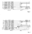
- Fig. 3 shows the signals necessary for operating the steering system in a first embodiment of a signal plausibility chain.
- the steering wheel angle ⁇ S is already sufficiently plausible as an external signal.
- vehicle speed v X , pinion angle ⁇ G , phase currents and voltages U, V, W of the motor 23 (shown in FIG. 4) and the motor angle ⁇ M are necessary for operating the useful applications (steering assistance and actuator functions).
- the wheel speeds namely the front wheel speeds ⁇ F j and the rear wheel speeds are ⁇ Rj available. All signals are initially subjected to a communication check to the source (ComC), a sensor diagnosis (SD) and an area and gradient check (RGC).
- ComC the source
- SD sensor diagnosis
- RRC area and gradient check
- MAM can be made plausible by the electronics-dependent safety functions e / e / pes_sf as well as by the application-related safety functions app_sf, depending on whether a load model is integrated or not.
- the problem can be with the help of the wheel speeds for plausibility an intervention of the ESP (Electronic Stability Program) since this affects the wheel speeds.
- an intervention of the ESP Electronic Stability Program
- To this problem inevitably has to monitor the status of the ESP (for example by checking the ESP status bits). and this in the plausibility considered accordingly (for example, by selecting the wheel speeds unaffected wheels).
- the model-based monitoring functions (e.g., VXP, AMA, PAP, MAM) for generating a second signal channel have a common structure: for calculation the signal is a verified model, whose inputs are filtered first. Of the Difference between measured and calculated signal is then judged in its size and this quality statement if necessary filtered over a certain period of time. In addition, it must be decided whether the model in current driving condition is valid.
- the safety function AMA (angle monitoring - A ngle M onitoring A lgorithm) monitors the constraining relationship between the three angles of the superimposed steering system (see equation (2).). Ie. the motor angle ⁇ M or the steering wheel angle ⁇ S is plausibilized by means of pinion angle ⁇ G and steering wheel angle ⁇ S or motor angle ⁇ M. The sum equation (2) is used to determine the third from two already plausibilized angles. In a plausibility check of the steering wheel angle ⁇ S lower demands on the steering wheel angle sensor 28 can be made in an advantageous manner. This results in a higher availability of the overall steering system by the additional fallback level created thereby.
- the safety function PAP calculates the pinion angle ⁇ G of the two front wheel speeds ⁇ Fj and compares the calculated value with the sensor value.
- an application-related safety function could also computationally determine the pinion angle ⁇ G (based on the safety function AMA with motor ⁇ M and steering wheel angle ⁇ S as the useful signal inputs) and plausibility check on the basis of the safety function PAP, which would make a pinion angle sensor superfluous.
- increased demands were placed on the steering wheel angle ⁇ S and the steering wheel angle sensor 28.
- the safety monitoring method for the steering system in the context of the inventive method for operating a steering system is divided into several layers (not shown) and implemented as a computer program on the controller 27 (in other embodiments, of course, other implementation variants are conceivable).
- the input data of the controller 27 are checked for plausibility by means of suitable security functions.
- the useful applications of the steering system are configured, ie the actuator 13, 23 for initiating the movement ⁇ M controlled by the control signal u of the control unit 27 accordingly.
- An E / E / PES monitoring layer is used for monitoring electric / electronic / programmable electronic Systems (E / E / PES) and performs the electronics-dependent Security functions e / e / pes_sf.
- An application monitoring layer executes application-related security functions app_sf, eg the monitoring AMA of the sum of the angles of the steering system ( ⁇ S , ⁇ M ).
- a signal layer is used, which has a signal status of the steering system, the signal layer as input the results of the E / E / PES monitoring layer and the application monitoring layer receives.
- a system status layer determines a system status the steering system status based on the results of the signal layer and the application monitoring layer.
- An application configuration layer configures the User applications due to the system health layer calculated system status of the steering system and the results of the signal layer, d. H. the application configuration layer turns off the payloads, For example, the variable steering ratio and starts replacement modes if necessary.
Landscapes
- Engineering & Computer Science (AREA)
- Transportation (AREA)
- Mechanical Engineering (AREA)
- Chemical & Material Sciences (AREA)
- Combustion & Propulsion (AREA)
- Physics & Mathematics (AREA)
- Mathematical Physics (AREA)
- Steering Control In Accordance With Driving Conditions (AREA)
Applications Claiming Priority (2)
| Application Number | Priority Date | Filing Date | Title |
|---|---|---|---|
| DE102004009822 | 2004-02-28 | ||
| DE200410009822 DE102004009822A1 (de) | 2004-02-28 | 2004-02-28 | Verfahren zum Betrieb eines Lenksystems mit Signalplausibilisierung |
Publications (2)
| Publication Number | Publication Date |
|---|---|
| EP1568572A2 true EP1568572A2 (fr) | 2005-08-31 |
| EP1568572A3 EP1568572A3 (fr) | 2006-07-05 |
Family
ID=34745322
Family Applications (1)
| Application Number | Title | Priority Date | Filing Date |
|---|---|---|---|
| EP05001643A Withdrawn EP1568572A3 (fr) | 2004-02-28 | 2005-01-27 | Procédure de commande de direction véhicule avec vérification de plausibilité de signal |
Country Status (2)
| Country | Link |
|---|---|
| EP (1) | EP1568572A3 (fr) |
| DE (1) | DE102004009822A1 (fr) |
Cited By (1)
| Publication number | Priority date | Publication date | Assignee | Title |
|---|---|---|---|---|
| DE102012014911A1 (de) | 2012-07-27 | 2014-01-30 | Volkswagen Aktiengesellschaft | Verfahren und Vorrichtung zur Überwachung einer Bestimmung eines Unterstützungsmoments |
Families Citing this family (4)
| Publication number | Priority date | Publication date | Assignee | Title |
|---|---|---|---|---|
| DE102006040443B4 (de) * | 2006-08-29 | 2011-01-27 | Zf Lenksysteme Gmbh | Verfahren zum Betrieb eines elektronisch geregelten Servolenksystems |
| DE102008021847B4 (de) * | 2008-05-02 | 2017-02-23 | Volkswagen Ag | Elektromechanisches Lenksystem und Verfahren zur Steuerung eines elektromechanischen Lenksystems |
| DE102009009448B4 (de) * | 2009-02-13 | 2021-02-04 | Volkswagen Ag | Verfahren und Vorrichtung zur Eigendiagnose mindestens einer zu diagnostizierenden Sensoreinheit einer elektromechanischen Lenkung |
| US12539915B2 (en) * | 2024-06-10 | 2026-02-03 | GM Global Technology Operations LLC | Steering road wheel pinion angle estimation and sensory validation |
Family Cites Families (14)
| Publication number | Priority date | Publication date | Assignee | Title |
|---|---|---|---|---|
| DE19618624C1 (de) * | 1996-05-09 | 1997-09-25 | Daimler Benz Ag | Vorrichtung zur Auswertung von Signalen |
| JP3462007B2 (ja) * | 1996-06-10 | 2003-11-05 | 三菱電機株式会社 | 直流モータの回転角および負荷トルク検出方法、直流モータ制御装置および電動式パワーステアリング装置 |
| DE19751251A1 (de) | 1997-11-19 | 1999-05-20 | Hoechst Marion Roussel De Gmbh | Substituierte Imidazolidinderivate, ihre Herstellung, ihre Verwendung und sie enthaltende pharmezeutische Präparate |
| DE19902939B4 (de) * | 1998-09-02 | 2015-01-08 | Continental Teves Ag & Co. Ohg | Verfahren und Vorrichtung zum Ersetzen eines fehlerhaften Sensorsignals |
| DE19943960A1 (de) * | 1999-09-14 | 2001-03-15 | Bosch Gmbh Robert | Verfahren und Vorrichtung zum Betreiben eines Stellelements in einem Fahrzeug |
| DE10002519C1 (de) * | 2000-01-21 | 2001-04-05 | Siemens Ag | Verfahren zur Verhinderung von Fehlfunktionen in einem signalverarbeitenden System und Prozessorsystem |
| DE10012133A1 (de) * | 2000-03-13 | 2001-09-27 | Bosch Gmbh Robert | Überwachungssystem zur Überwachung einer Stelleinrichtung im Kraftfahrzeug |
| DE10032340A1 (de) * | 2000-07-04 | 2002-01-31 | Bosch Gmbh Robert | Verfahren zum Lenken eines Fahrzeugs mit Servolenkung |
| DE10039782A1 (de) * | 2000-08-16 | 2002-02-28 | Daimler Chrysler Ag | Verfahren zur Regelung der Gier-und Querdynamik bei einem Straßenfahrzeug |
| DE10045385A1 (de) * | 2000-09-14 | 2002-03-28 | Bayerische Motoren Werke Ag | Vorrichtung und Verfahren zur elektronischen Steuerung eines einem Regelsystem zugeordneten Aktuators in Kraftfahrzeugen |
| DE10052343A1 (de) * | 2000-10-21 | 2002-07-11 | Bosch Gmbh Robert | Verfahren zum Steuern eines Steerby-Wire-Lenksystems |
| DE10109491A1 (de) * | 2001-02-28 | 2002-09-19 | Bosch Gmbh Robert | Verfahren und Computerprogramm zum Betrieb einer Fahrzeuglenkung, Steuer- und/oder Regelgerät für eine Fahrzeuglenkung sowie Fahrzeuglenkung |
| DE10248343A1 (de) * | 2002-02-13 | 2003-08-21 | Continental Teves Ag & Co Ohg | Verfahren zur Ansteuerung eines Betätigungskraftsimulators einer Fahrzeuglenkung |
| DE10328752A1 (de) * | 2002-07-05 | 2004-02-05 | Continental Teves Ag & Co. Ohg | Verfahren zum Lenken eines Fahrzeugs mit einer Überlagerungslenkung |
-
2004
- 2004-02-28 DE DE200410009822 patent/DE102004009822A1/de not_active Withdrawn
-
2005
- 2005-01-27 EP EP05001643A patent/EP1568572A3/fr not_active Withdrawn
Cited By (2)
| Publication number | Priority date | Publication date | Assignee | Title |
|---|---|---|---|---|
| DE102012014911A1 (de) | 2012-07-27 | 2014-01-30 | Volkswagen Aktiengesellschaft | Verfahren und Vorrichtung zur Überwachung einer Bestimmung eines Unterstützungsmoments |
| EP2698303A2 (fr) | 2012-07-27 | 2014-02-19 | Volkswagen Aktiengesellschaft | Procédé et dispositif de surveillance d'une détermination d'un moment de soutien |
Also Published As
| Publication number | Publication date |
|---|---|
| EP1568572A3 (fr) | 2006-07-05 |
| DE102004009822A1 (de) | 2005-09-15 |
Similar Documents
| Publication | Publication Date | Title |
|---|---|---|
| DE112015000941B4 (de) | Fahrzeugseitige Vorrichtungssteuereinheit und Lenkunterstützungsvorrichtung | |
| EP3584140B1 (fr) | Procédé et dispositif de commande d'un processus de sécurité ainsi que véhicule | |
| WO2016128175A2 (fr) | Boîtier de capteur pour un dispositif capteur de vitesse de roue, dispositif capteur de vitesse de roue et son composant de raccordement | |
| EP3898383B1 (fr) | Procédé de détermination d'une sensation de direction d'un système de direction à commande électrique | |
| DE10247975B4 (de) | Verfahren zum Betreiben einer Lenkung, ein Computerprogramm, ein Steuergerät sowie eine Lenkung für ein Fahrzeug | |
| EP3473512A1 (fr) | Module fonctionnel, unité de commande pour un système d'aide au fonctionnement et dispositif de travail | |
| DE102022214324A1 (de) | Lenksteuervorrichtung und -verfahren eines fahrzeugs | |
| DE102022200887A1 (de) | Lenksteuerungsvorrichtung, lenkunterstützungsvorrichtung und verfahren | |
| DE102008038891B4 (de) | Vorrichtung und Verfahren zur Erfassung eines Drehmomentes an einer elektromechanischen Lenkung | |
| DE102022204291A1 (de) | Verfahren zum Betreiben eines Steer-by-Wire-Lenksystems und Steer-by-Wire-Lenksystem | |
| DE102020201286B4 (de) | Verfahren zum Betrieb einer Überlagerungslenkung eines Kraftfahrzeugs | |
| EP4173150A1 (fr) | Ensemble capteur | |
| EP4530158B1 (fr) | Système de direction à commande électrique, véhicule automobile et procédé de détermination d'un angle de direction absolu | |
| EP1568572A2 (fr) | Procédure de commande de direction véhicule avec vérification de plausibilité de signal | |
| EP1607307B1 (fr) | Procédé pour la commande d'un système de direction | |
| DE19720440A1 (de) | Verfahren zur Regelung einer dynamischen Zustandsgröße eines Fahrzeugs | |
| DE102004014391A1 (de) | Verteilte Regelung eines Lenksystems mit Kommunikationsnetzwerk mit zeitgetriggertem Protokoll | |
| WO2024188388A1 (fr) | Système de direction à commande électrique pour un véhicule à moteur et procédé | |
| EP1568573A1 (fr) | Procédé pour le commande d'un système de direction | |
| DE102004028827A1 (de) | Verfahren zum Betrieb eines Lenksystems | |
| EP1568570A2 (fr) | Calcul d'un angle de braquage d'une roue de voiture | |
| EP1568575B1 (fr) | Procédé de commande d'un système de direction avec configuration de modes d'opération | |
| DE102013000203B4 (de) | Verfahren zur Ermittlung einer Art einer Lenkbewegung und Verfahren zur Überwachung eines Fahrerzustandes | |
| DE102008021847B4 (de) | Elektromechanisches Lenksystem und Verfahren zur Steuerung eines elektromechanischen Lenksystems | |
| DE102010049431A1 (de) | Verfahren zur Diagnose mindestens einer zu diagnostizierenden Sensoreinheit einer elektromechanischen Lenkung und elektromechanische Lenkung |
Legal Events
| Date | Code | Title | Description |
|---|---|---|---|
| PUAI | Public reference made under article 153(3) epc to a published international application that has entered the european phase |
Free format text: ORIGINAL CODE: 0009012 |
|
| AK | Designated contracting states |
Kind code of ref document: A2 Designated state(s): AT BE BG CH CY CZ DE DK EE ES FI FR GB GR HU IE IS IT LI LT LU MC NL PL PT RO SE SI SK TR |
|
| AX | Request for extension of the european patent |
Extension state: AL BA HR LV MK YU |
|
| 17P | Request for examination filed |
Effective date: 20060202 |
|
| PUAL | Search report despatched |
Free format text: ORIGINAL CODE: 0009013 |
|
| AK | Designated contracting states |
Kind code of ref document: A3 Designated state(s): AT BE BG CH CY CZ DE DK EE ES FI FR GB GR HU IE IS IT LI LT LU MC NL PL PT RO SE SI SK TR |
|
| AX | Request for extension of the european patent |
Extension state: AL BA HR LV MK YU |
|
| 17Q | First examination report despatched |
Effective date: 20060830 |
|
| AKX | Designation fees paid |
Designated state(s): DE FR GB IT SE |
|
| STAA | Information on the status of an ep patent application or granted ep patent |
Free format text: STATUS: THE APPLICATION IS DEEMED TO BE WITHDRAWN |
|
| 18D | Application deemed to be withdrawn |
Effective date: 20070110 |