EP1568577A2 - Système de direction pour un véhicule et procédé pour le commande d'un tel système de direction - Google Patents
Système de direction pour un véhicule et procédé pour le commande d'un tel système de direction Download PDFInfo
- Publication number
- EP1568577A2 EP1568577A2 EP05001777A EP05001777A EP1568577A2 EP 1568577 A2 EP1568577 A2 EP 1568577A2 EP 05001777 A EP05001777 A EP 05001777A EP 05001777 A EP05001777 A EP 05001777A EP 1568577 A2 EP1568577 A2 EP 1568577A2
- Authority
- EP
- European Patent Office
- Prior art keywords
- angle
- steering
- steering system
- angles
- motor vehicle
- Prior art date
- Legal status (The legal status is an assumption and is not a legal conclusion. Google has not performed a legal analysis and makes no representation as to the accuracy of the status listed.)
- Withdrawn
Links
Images


Classifications
-
- B—PERFORMING OPERATIONS; TRANSPORTING
- B62—LAND VEHICLES FOR TRAVELLING OTHERWISE THAN ON RAILS
- B62D—MOTOR VEHICLES; TRAILERS
- B62D5/00—Power-assisted or power-driven steering
- B62D5/04—Power-assisted or power-driven steering electrical, e.g. using an electric servo-motor connected to, or forming part of, the steering gear
- B62D5/0457—Power-assisted or power-driven steering electrical, e.g. using an electric servo-motor connected to, or forming part of, the steering gear characterised by control features of the drive means as such
- B62D5/0481—Power-assisted or power-driven steering electrical, e.g. using an electric servo-motor connected to, or forming part of, the steering gear characterised by control features of the drive means as such monitoring the steering system, e.g. failures
- B62D5/0493—Power-assisted or power-driven steering electrical, e.g. using an electric servo-motor connected to, or forming part of, the steering gear characterised by control features of the drive means as such monitoring the steering system, e.g. failures detecting processor errors, e.g. plausibility of steering direction
-
- B—PERFORMING OPERATIONS; TRANSPORTING
- B62—LAND VEHICLES FOR TRAVELLING OTHERWISE THAN ON RAILS
- B62D—MOTOR VEHICLES; TRAILERS
- B62D5/00—Power-assisted or power-driven steering
- B62D5/008—Changing the transfer ratio between the steering wheel and the steering gear by variable supply of energy, e.g. by using a superposition gear
-
- B—PERFORMING OPERATIONS; TRANSPORTING
- B62—LAND VEHICLES FOR TRAVELLING OTHERWISE THAN ON RAILS
- B62D—MOTOR VEHICLES; TRAILERS
- B62D5/00—Power-assisted or power-driven steering
- B62D5/04—Power-assisted or power-driven steering electrical, e.g. using an electric servo-motor connected to, or forming part of, the steering gear
- B62D5/0457—Power-assisted or power-driven steering electrical, e.g. using an electric servo-motor connected to, or forming part of, the steering gear characterised by control features of the drive means as such
- B62D5/0481—Power-assisted or power-driven steering electrical, e.g. using an electric servo-motor connected to, or forming part of, the steering gear characterised by control features of the drive means as such monitoring the steering system, e.g. failures
- B62D5/049—Power-assisted or power-driven steering electrical, e.g. using an electric servo-motor connected to, or forming part of, the steering gear characterised by control features of the drive means as such monitoring the steering system, e.g. failures detecting sensor failures
Definitions
- the present invention relates to a steering system for a Motor vehicle.
- the steering system includes a steering handle for Specification of a steering wheel angle as a measure of a desired Steering angle for at least one steerable wheel of the Motor vehicle. It also includes the steering system Overlay means for generating an additional angle and for superposition of the steering wheel angle with the additional angle. The angle resulting from the overlay is called Pinion angle called.
- the steering system includes a steering gear to implement the pinion angle in a Steering angle for the at least one steerable wheel of Motor vehicle.
- the invention also relates to a method of operation a steering system of a motor vehicle. It is by means of a steering handle a steering wheel angle as a measure of a desired steering angle for at least one steerable wheel of Motor vehicle specified. In addition, an additional angle generated and to determine a pinion angle the Steering wheel angle superimposed. Finally, the pinion angle in a steering angle for the at least one steerable wheel implemented the motor vehicle.
- the present invention relates to a Computer program running on a computing device, in particular on a microprocessor, a controller for a Steering system of a motor vehicle is executable.
- a steering system of the type mentioned is For example, from DE 100 13 711 A1 known. There is described a steering system, in addition to those mentioned Features also a servo drive for torque assistance having.
- the degree of torque support is dependent from the driving speed of the motor vehicle. While at slow driving speed, the torque assistance is greater (for example, when maneuvering the vehicle to operate the steering wheel without much effort), is the torque support at higher speeds (For example, the driving stability in a highway ride to increase) significantly smaller.
- the servo drive can work electrically or hydraulically. That too steering system according to the invention can be a servo drive exhibit. But the invention is also for such Steering systems of importance that no servo drive exhibit.
- a steering handle for example, a steering wheel, a Handlebar or one or more handlebars used become.
- a steering system with overlay means is For example, from DE 40 31 316 Al known. With help the overlay means it is possible to use one of the Lenkhandhabe given steering wheel angle to increase the Driving stability and / or comfort with one Superimpose additional angle, so that Depending on the driving dynamics and / or comfort a variable Gear ratio between steering wheel angle and middle Steering angle of the steerable wheels of the motor vehicle established. This makes it possible from a safety point of view Motor vehicle threatening to break out by one Corresponding correction of the steering angle back into a Stable driving situation due.
- the overlay means can other driving dynamics (eg Electronic Stability Program (ESP) Anti-lock braking system (ABS), a traction control system (ASR), etc.).
- ESP Electronic Stability Program
- ABS Anti-lock braking system
- ASR traction control system
- a steering wheel angle for example, a superimpose speed-dependent additional angle. This can be at low vehicle speeds to set relatively small gear ratio, the means a relatively small rotation of the steering handle leads to a relatively large steering angle of the wheels.
- At high Vehicle speeds on the other hand, can be a relatively large one Gear ratio can be adjusted so that the Improved driving stability of the motor vehicle.
- the present invention is based on the object, the Functional reliability, reliability and availability of To improve steering systems of the type mentioned.
- the Steering system means for determining an angular value of one of the angles from the group steering wheel angle, additional angle and pinion angle based on angle values of the other two Angle and taking into account the kinematic Has relationship between the three angles.
- the kinematic Relationship between the three angles of the steering system namely steering wheel angle, additional angle and pinion angle, too determine. It is also proposed, on the basis of two of the three angles to determine the third angle. To one as accurate as possible determination of the third angle allow this, taking into account the kinematic relationship between the three angles determined. On the one hand it is about, one possible to determine the exact model of the steering system with which Help the third angle can be determined. on the other hand should be the kinematic relationship between the three angles However, as simple as possible to describe the Calculation of the third angle required computational effort keep as low as possible.
- the steering system means for the plausibility check of the one angle on the basis of the means determined angular value of the one angle having.
- the Steering system Means for measuring the angular values of the two other angle up.
- the steering system Means for modeling the angle values of the other two Angle based on other sizes.
- the determined angle value for the third angle can in the Framework of operation of the steering system as a third angle be used. But it is also conceivable that the According to the invention determined angle value for the third Angle with another way (for example, through Measurement) determined angle value for the third angle compared and thus the plausibility of the angle value of third angle is checked.
- the additional angle and the pinion angle means appropriate sensors to measure and the steering wheel angle to monitor the two measured angles. This will be based on the additional angle and the pinion angle Angle value determined for the steering wheel angle and this one Subject to plausibility check. It is also possible the additional angle based on the other two measured Determine the angle.
- the additional angle for example by means of a suitable function or be determined on the basis of a suitable model, whereas the pinion angle is measured by means of a sensor becomes.
- the steering wheel angle can be modeled based on the model Angle and the measured angle. To is determined by the additional angle and the pinion angle Angle value determined for the steering wheel angle and this one Subject to plausibility check.
- the pinion angle using modeled or measured angle values for the steering wheel angle and the Additional angle to determine the pinion angle or to monitor.
- the means in determining the angle value of the one angle Propeller error between the steering handle and the Steering gear arranged PTO shaft or a den Take account of the size characterizing the gimbal. It has proven that the gimbal is a big one Influence on the kinematic relationship of the three angles, namely steering wheel angle, additional angle and pinion angle, has to each other. By compensating the gimbal error results in a particularly high static accuracy of Steering system.
- the steering system means of identification of the gimbal error using an analytic equation having.
- the equation allows a highly accurate Consideration of the gimbal error in the determination of the third angle from the other two angles.
- the present invention proposes that the means in determining the angle value of the one angle from the steering wheel angular velocity or one of these characterizing size dependent dynamic error consider.
- the steering system means of modeling the dynamic Error based on a differential equation.
- the gimbal error and the dynamic error can be combined to form a compensation function, which is taken into account when determining the angle value of the one angle.
- a virtual Steering angle Based on the compensation function and a virtual Steering angle can be a deviation of the kinematic Relationship of the angles of the steering system with each other be determined when determining the angle value of one angle is taken into account.
- the permissible value of the deviation is Range of a stop of the steering gear is greater than in the Center position of the steering.
- the steering system In the end positions of the steering, for example in the area of a rack end stop, the steering system has a clear due to tension increased deviation.
- the permissible value increased in the range of the end positions of the steering. In this way, the availability of the steering system elevated.
- the means take into account in the determination the angular value of the one angle the gimbal error and / or the dynamic error depending on one Driving speed of the motor vehicle.
- the gimbal error and the dynamic error are not so over the entire range of driving speed constant, but rather than depending on the driving speed of the Considered motor vehicle. So it will be the effects the driving speed on the gimbal error and / or on compensates for the dynamic error. Also through this Measure increases the availability of the steering system.
- the steering system includes a servo drive for Torque assistance.
- a servo drive for Torque assistance is dependent.
- the one angle based on the determined Angle value of the one angle checked for plausibility becomes.
- At least one of the angle values of the other two Angle used to determine the angular value of the one Angles are used, is measured.
- At least one of the angle values of two other angles used to determine the angle value of one angle, on the basis of others Sizes is modeled.
- the computer program is on one Computing device, in particular on a microprocessor, executable and for the execution of the invention Suitable method.
- the invention realized by the computer program, so this Computer program in the same way represents the invention like the method that the Computer program is programmed.
- the computer program is preferably stored on a memory element.
- Memory element may in particular an electrical Storage medium are used, for example, a Random access memory, a read-only memory or a Flash memory.
- the memory element can also be used as a magnetic storage medium (eg floppy disk, hard disk, Memory tape) or optical storage medium (eg DVD, CD-ROM, etc.).
- FIG. 1 shows a steering system according to the invention Motor vehicle in its entirety by the reference numeral 1 designated.
- the steering system 1 comprises a steering handle 2, for example, as a steering wheel, as a handlebar or can be designed as a steering stick.
- the Steering handle 2 is about a propeller shaft 3 with a Steering gear 4 in conjunction.
- the propeller shaft 3 is depending on Embodiment of the steering system 1 by one or more Cardan joints 5, 6 interrupted.
- the steering gear 4 is used to a rotation angle of the propeller shaft 3 in a Steering angle ⁇ _F of wheels to be steered 12, 13 of the Implement motor vehicle.
- the steering gear 4 comprises in the embodiment shown in Figure 1 a Rack 7 and a pinion 8, to which the propeller shaft. 3 attacks.
- the steering system 1 also has Superposition means 9, which has an electric motor 10 and a driven by this superposition gear 11 in Form of a planetary gear include.
- a steering wheel angle ⁇ _S as a measure for a desired steering angle ⁇ _F of the steerable wheels 12, 13 of the motor vehicle specified.
- the additional angle ⁇ _M becomes Improvement of the driving dynamics of the motor vehicle and / or of comfort generated.
- the sum angle of steering wheel angle ⁇ _S and additional angle ⁇ _M is called the pinion angle ⁇ _G designated.
- a servo drive 14th In the region of the steering gear 4 is a servo drive 14th arranged, which serves for moment support.
- the Servo drive 14 includes a hydraulic pump 15, which is a Hydraulic fluid from a reservoir 16 via a Hydraulic valve 17 promotes the steering gear 4. More accurate said, the handlebar 7 and the pinion 8 are in one Housing 18 of the steering gear 4 is arranged.
- the Hydraulic valve 17 is electromagnetic or via a Piezo actuator can be actuated.
- About the Hydraulic valve 17 is the flow of hydraulic fluid to one or the other end of the handlebar. 7 controlled, and so a momentum support in the one or other direction causes.
- About the crowd and thus the Pressure of funded in the housing 18 of the steering gear 4 Hydraulic fluid can be the strength of Momentsupport can be varied.
- hydraulic servo drive 14 may also be a electric servo drive are provided
- the steering system 1 also has a control unit 19, Among other things, to control the motor 10 of Superposition means 9 and the hydraulic valve 17 of the Servo drive 14 is used.
- the hydraulic valve 17 is so that depends on the Driving speed V_x of the motor vehicle a variable Moments support set. That's the way it is, for example possible, at low speeds V_x a high To select torque assistance to maneuver the Facilitate vehicles and at high speeds V_x (eg for speedy overland or motorway travel) one to set low torque assistance to one driving dynamics particularly stable steering of the vehicle too enable.
- the steering system 1 has suitable Rotation angle sensors 20, 21, 22, which the steering wheel angle ⁇ _S, the additional angle ⁇ _M and the pinion angle ⁇ _G measure.
- the rotation angle signals ⁇ _S, ⁇ _M and ⁇ _G also become the control unit 19 out.
- the object of the method according to the invention is the kinematic relationship between the three sizes Steering wheel angle ⁇ _S, additional angle ⁇ _M and pinion angle ⁇ _G too monitor.
- the steering system 1 is not a rigid body system represents, in addition to the static consideration of Relationship the dynamic behavior between the three Angles ⁇ _S, ⁇ _M and ⁇ _G are taken into account.
- This is a massless Universal joint 5 or 6 considered, which two parts of the PTO shaft 3 is skewed together. Since the spatial kink angles of cardan joints 5 or 6 in each Vehicle type varies, the inventive method be adjusted accordingly for each vehicle type.
- the pinion angle ⁇ _G with the gear ratio i_D between steering wheel angle ⁇ _S and pinion angle ⁇ _G acted upon.
- the additional angle ⁇ _M is with the quotient of the gear ratios i_D / i_M is applied, where i_M is the gear ratio between the additional angle ⁇ _M and the pinion angle ⁇ _G.
- a virtual steering wheel angle ⁇ _S_MOD results from the Difference of the product from pinion angle ⁇ _G and Gear ratio i_D and the product off Additional angle ⁇ _M and the quotient of Translation ratios i_D and i_M.
- ⁇ _S_MOD ⁇ _G ⁇ i_D - ⁇ _M ⁇ i_D / i_M.
- ⁇ _S_MOD Steering wheel angle ⁇ _ S_korr with the virtual steering wheel angle ⁇ _S_MOD and depending on the result of the Comparison a status signal AMA_Status output.
- ⁇ G 1 i M ⁇ ⁇ M + 1 i D ⁇ ⁇ S
- ⁇ S MOD i D ⁇ ⁇ G - i D i M ⁇ ⁇ M
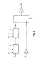
- FIG. 3 shows a further exemplary embodiment of the invention inventive method shown. It will assuming that two of the three angles ⁇ _S, ⁇ _M are correct, the third angle ⁇ _G determined. Thereby for example, the sensor 22 may measure the pinion angle ⁇ _G be saved.
- the left Function inputs and on the right the function outputs shown.
- the steering wheel angle ⁇ _S is over the first Function block 30 for compensating the Kardan réelles and the second function block 31 for dynamically correcting the Steering wheel angle out. As an output of these two Function blocks 30, 31 results in the corrected Steering wheel angle ⁇ _S_korr.
- the additional angle ⁇ _M is with the Quotients of the gear ratios i_D / i_M applied.
- the inventive method is preferably in the form a computer program realized on a Computing device 23, in particular on a microprocessor, the Control unit 19 of the steering system 1 can run.
- the Computer program is on a memory element in particular on an electrical storage element 24 in Form of a read-only memory, random access memory or flash memory, saved.
- the inventive method carried out.
- determined or received Values can be sent over the data link 25 to the Memory element 24 is transmitted and stored there become.
- the gimbal error x_d_Kardan and that of the Steering wheel angular velocity ⁇ ⁇ s dependent dynamic error regardless of the vehicle speed V_x determined and considered accordingly.
- gimbal error x_d_Kardan and the dynamic error dependent on the steering wheel angular velocity ⁇ ⁇ s are determined as a function of the vehicle speed V_x.
- the vehicle speed V_x is introduced as an input signal to the function blocks 30, 31 and 33 in FIGS. 2 and 3 and taken into account accordingly there.
- the effects of the vehicle speed V x on the gimbal error x_d_Kardan and on the dynamic error are compensated.
- the availability of the steering system 1 can be increased.
Landscapes
- Engineering & Computer Science (AREA)
- Chemical & Material Sciences (AREA)
- Combustion & Propulsion (AREA)
- Transportation (AREA)
- Mechanical Engineering (AREA)
- Steering Control In Accordance With Driving Conditions (AREA)
Applications Claiming Priority (2)
| Application Number | Priority Date | Filing Date | Title |
|---|---|---|---|
| DE102004009816 | 2004-02-28 | ||
| DE200410009816 DE102004009816A1 (de) | 2004-02-28 | 2004-02-28 | Lenksystem für ein Kraftfahrzeug und Verfahen zum Betrieb des Lenksystems |
Publications (2)
| Publication Number | Publication Date |
|---|---|
| EP1568577A2 true EP1568577A2 (fr) | 2005-08-31 |
| EP1568577A3 EP1568577A3 (fr) | 2006-11-08 |
Family
ID=34745317
Family Applications (1)
| Application Number | Title | Priority Date | Filing Date |
|---|---|---|---|
| EP05001777A Withdrawn EP1568577A3 (fr) | 2004-02-28 | 2005-01-28 | Système de direction pour un véhicule et procédé pour le commande d'un tel système de direction |
Country Status (2)
| Country | Link |
|---|---|
| EP (1) | EP1568577A3 (fr) |
| DE (1) | DE102004009816A1 (fr) |
Cited By (6)
| Publication number | Priority date | Publication date | Assignee | Title |
|---|---|---|---|---|
| EP2019020A3 (fr) * | 2007-07-25 | 2009-12-30 | Denso Corporation | Appareil de direction assistée doté d'un dispositif de détection de défaillance pour capteurs d'angle de rotation |
| WO2010124883A1 (fr) * | 2009-04-29 | 2010-11-04 | Zf Lenksysteme Gmbh | Réglage d'un angle de braquage de roue et d'un couple manuel dans un système de direction |
| ITBO20120038A1 (it) * | 2012-01-27 | 2013-07-28 | Ferrari Spa | Metodo ed unita' di controllo di un sistema di sterzatura di una vettura stradale |
| DE102012002772A1 (de) | 2012-02-11 | 2013-08-14 | Volkswagen Aktiengesellschaft | Elektromechanisches Lenksystem und Verfahren zum Betrieb eines elektromechanischen Lenksystems |
| CN103921841A (zh) * | 2013-01-15 | 2014-07-16 | 福特全球技术公司 | 转向角度误差的校正方法 |
| US10787192B1 (en) | 2017-04-11 | 2020-09-29 | Apple Inc. | Steer-by-wire system with multiple steering actuators |
Families Citing this family (4)
| Publication number | Priority date | Publication date | Assignee | Title |
|---|---|---|---|---|
| JP4254777B2 (ja) | 2005-11-11 | 2009-04-15 | トヨタ自動車株式会社 | 車輌用操舵制御装置 |
| DE102006040443B4 (de) * | 2006-08-29 | 2011-01-27 | Zf Lenksysteme Gmbh | Verfahren zum Betrieb eines elektronisch geregelten Servolenksystems |
| DE102008045243B4 (de) * | 2008-05-02 | 2020-01-16 | Volkswagen Ag | Servo-Lenksystem und Verfahren zur Reduzierung von Kreuzgelenk-Fehlern |
| KR101349464B1 (ko) | 2012-07-05 | 2014-01-09 | 현대자동차주식회사 | 상용 하이브리드 전동 조향장치 및 이의 제어를 통한 성능 및 연비 개선방법 |
Family Cites Families (9)
| Publication number | Priority date | Publication date | Assignee | Title |
|---|---|---|---|---|
| DE4031316C2 (de) * | 1990-10-04 | 2001-11-22 | Bosch Gmbh Robert | Motorbetriebenes Servolenksystem |
| JPH07246947A (ja) * | 1994-03-11 | 1995-09-26 | Aisin Seiki Co Ltd | 車輌の操舵制御装置 |
| US6186267B1 (en) * | 1997-03-22 | 2001-02-13 | Robert Bosch Gmbh | Method and apparatus for operating a steering system for a motor vehicle |
| DE10011140A1 (de) * | 1999-04-19 | 2000-11-02 | Thyssen Krupp Automotive Ag | Rohrförmige, elektrisch unterstützte Lenkhilfe mit hohem Wirkungsgrad |
| DE10012133A1 (de) * | 2000-03-13 | 2001-09-27 | Bosch Gmbh Robert | Überwachungssystem zur Überwachung einer Stelleinrichtung im Kraftfahrzeug |
| DE10013711A1 (de) * | 2000-03-20 | 2001-10-11 | Bosch Gmbh Robert | Servounterstütztes Lenksystem eines Kraftfahrzeugs |
| DE10032340A1 (de) * | 2000-07-04 | 2002-01-31 | Bosch Gmbh Robert | Verfahren zum Lenken eines Fahrzeugs mit Servolenkung |
| DE10328752A1 (de) * | 2002-07-05 | 2004-02-05 | Continental Teves Ag & Co. Ohg | Verfahren zum Lenken eines Fahrzeugs mit einer Überlagerungslenkung |
| DE10247975B4 (de) * | 2002-10-15 | 2014-03-27 | Robert Bosch Gmbh | Verfahren zum Betreiben einer Lenkung, ein Computerprogramm, ein Steuergerät sowie eine Lenkung für ein Fahrzeug |
-
2004
- 2004-02-28 DE DE200410009816 patent/DE102004009816A1/de not_active Withdrawn
-
2005
- 2005-01-28 EP EP05001777A patent/EP1568577A3/fr not_active Withdrawn
Cited By (11)
| Publication number | Priority date | Publication date | Assignee | Title |
|---|---|---|---|---|
| EP2019020A3 (fr) * | 2007-07-25 | 2009-12-30 | Denso Corporation | Appareil de direction assistée doté d'un dispositif de détection de défaillance pour capteurs d'angle de rotation |
| US7743875B2 (en) | 2007-07-25 | 2010-06-29 | Denso Corporation | Power steering apparatus having failure detection device for rotation angle sensors |
| CN101353051B (zh) * | 2007-07-25 | 2012-01-11 | 株式会社电装 | 具有用于旋转角传感器的故障检测设备的动力转向装置 |
| WO2010124883A1 (fr) * | 2009-04-29 | 2010-11-04 | Zf Lenksysteme Gmbh | Réglage d'un angle de braquage de roue et d'un couple manuel dans un système de direction |
| ITBO20120038A1 (it) * | 2012-01-27 | 2013-07-28 | Ferrari Spa | Metodo ed unita' di controllo di un sistema di sterzatura di una vettura stradale |
| EP2664515A1 (fr) * | 2012-01-27 | 2013-11-20 | FERRARI S.p.A. | Procédé et unité de commande pour système de direction |
| US8700264B2 (en) | 2012-01-27 | 2014-04-15 | Ferrari S.P.A. | Control method and unit for a steering system |
| DE102012002772A1 (de) | 2012-02-11 | 2013-08-14 | Volkswagen Aktiengesellschaft | Elektromechanisches Lenksystem und Verfahren zum Betrieb eines elektromechanischen Lenksystems |
| CN103921841A (zh) * | 2013-01-15 | 2014-07-16 | 福特全球技术公司 | 转向角度误差的校正方法 |
| US10787192B1 (en) | 2017-04-11 | 2020-09-29 | Apple Inc. | Steer-by-wire system with multiple steering actuators |
| US11370475B1 (en) | 2017-04-11 | 2022-06-28 | Apple Inc. | Steer-by-wire system with multiple steering actuators |
Also Published As
| Publication number | Publication date |
|---|---|
| EP1568577A3 (fr) | 2006-11-08 |
| DE102004009816A1 (de) | 2005-09-15 |
Similar Documents
| Publication | Publication Date | Title |
|---|---|---|
| DE102011055339B4 (de) | Verfahren zum bestimmen einer zahnstangenkraft für eine lenkvorrichtung und lenkvorrichtung | |
| DE19738161B4 (de) | Vorrichtung und Verfahren zum Erfassen eines Gegenlenkzustands | |
| DE10130879B4 (de) | Vorrichtung zum Bestimmen eines Straßenreibungskoeffizienten | |
| DE102016012242B4 (de) | Lenkungssteuerungsvorrichtung und lenkungssteuerungsverfahren | |
| DE102009022592B4 (de) | Verfahren zur Ermittlung des Fahrbahnreibwerts während des Betriebs eines Kraftfahrzeugs | |
| DE102020103755B4 (de) | SCHÄTZUNG EINES STRAßENREIBUNGSKOEFFIZIENTEN UNTER VERWENDUNGVON SIGNALEN EINES LENKSYSTEMS | |
| DE102006033458A1 (de) | Lenksteuersystem | |
| DE102020104265B4 (de) | Schätzung eines Straßenreibungskoeffizienten unter Verwendung von Signalen eines Lenksystems | |
| EP1807300A1 (fr) | Procede et dispositif permettant d'assister un serveur de vehicule lors de la stabilisation d'un vehicule | |
| DE10141425A1 (de) | Verfahren zur fahrzustandsabhängigen Lenkunterstützung | |
| DE112019001855B4 (de) | Fahrzeugsteuervorrichtung und eigenschaftsabschätzverfahren | |
| DE102017126209A1 (de) | Vorrichtung und Verfahren zum Ermitteln eines Lenkdrehmoments | |
| DE112012006440B4 (de) | Eigenschaftsänderungs-Erfassungseinrichtung für ein Lenkgetriebesystem | |
| DE112019007822T5 (de) | Lenkungshalte-Bestimmungsvorrichtung, Lenksteuervorrichtung und Lenkvorrichtung | |
| DE112019007814T5 (de) | Lenkungshalte-Bestimmungsvorrichtung, Lenksteuervorrichtung und Lenkvorrichtung | |
| EP1568576B1 (fr) | Système de direction et procédé pour la commande du système de direction | |
| EP3898383A1 (fr) | Procédé de détermination d'une sensation de direction d'un système de direction à commande électrique | |
| EP1568577A2 (fr) | Système de direction pour un véhicule et procédé pour le commande d'un tel système de direction | |
| DE102007053815B4 (de) | Vorrichtung zum Betrieb einer aktiven Lenkung eines Kraftfahrzeuges und Verfahren zum Betrieb einer aktiven Lenkung einer Frontachse eines Kraftfahrzeuges | |
| EP2977297B1 (fr) | Procede de determination d'un angle de direction d'un vehicule automobile, dispositif d'assistance et vehicule automobile | |
| DE10260752A1 (de) | Verfahren, Computerprogramm und Servolenkvorrichtung zum Erleichtern eines Lenkvorgangs für den Fahrer eines Kraftfahrzeugs | |
| DE102020213553B4 (de) | Lenksystem und Verfahren zum Betreiben eines Lenksystems | |
| WO2006087336A1 (fr) | Procede pour diriger un vehicule et systeme de direction de vehicule | |
| EP2407364B1 (fr) | Procédé et dispositif de reconnaissance et de compensation d'une inclinaison de la chaussée parcourue par un véhicule | |
| DE102021101411A1 (de) | Schwimmwinkelangepasste aktive Lenkungsrückstellung |
Legal Events
| Date | Code | Title | Description |
|---|---|---|---|
| PUAI | Public reference made under article 153(3) epc to a published international application that has entered the european phase |
Free format text: ORIGINAL CODE: 0009012 |
|
| AK | Designated contracting states |
Kind code of ref document: A2 Designated state(s): AT BE BG CH CY CZ DE DK EE ES FI FR GB GR HU IE IS IT LI LT LU MC NL PL PT RO SE SI SK TR |
|
| AX | Request for extension of the european patent |
Extension state: AL BA HR LV MK YU |
|
| PUAL | Search report despatched |
Free format text: ORIGINAL CODE: 0009013 |
|
| AK | Designated contracting states |
Kind code of ref document: A3 Designated state(s): AT BE BG CH CY CZ DE DK EE ES FI FR GB GR HU IE IS IT LI LT LU MC NL PL PT RO SE SI SK TR |
|
| AX | Request for extension of the european patent |
Extension state: AL BA HR LV MK YU |
|
| AKX | Designation fees paid | ||
| STAA | Information on the status of an ep patent application or granted ep patent |
Free format text: STATUS: THE APPLICATION IS DEEMED TO BE WITHDRAWN |
|
| 18D | Application deemed to be withdrawn |
Effective date: 20070509 |
|
| REG | Reference to a national code |
Ref country code: DE Ref legal event code: 8566 |