EP1568608A1 - Dispositif d'attenuation - Google Patents
Dispositif d'attenuation Download PDFInfo
- Publication number
- EP1568608A1 EP1568608A1 EP02793142A EP02793142A EP1568608A1 EP 1568608 A1 EP1568608 A1 EP 1568608A1 EP 02793142 A EP02793142 A EP 02793142A EP 02793142 A EP02793142 A EP 02793142A EP 1568608 A1 EP1568608 A1 EP 1568608A1
- Authority
- EP
- European Patent Office
- Prior art keywords
- slots
- revolution
- attenuation device
- elastic material
- slot
- Prior art date
- Legal status (The legal status is an assumption and is not a legal conclusion. Google has not performed a legal analysis and makes no representation as to the accuracy of the status listed.)
- Granted
Links
- 239000013013 elastic material Substances 0.000 claims abstract description 45
- 239000003190 viscoelastic substance Substances 0.000 claims description 6
- 239000000806 elastomer Substances 0.000 claims description 2
- 229920001971 elastomer Polymers 0.000 claims description 2
- 230000009021 linear effect Effects 0.000 description 13
- 230000037361 pathway Effects 0.000 description 10
- 239000000463 material Substances 0.000 description 7
- 239000011159 matrix material Substances 0.000 description 7
- 230000000694 effects Effects 0.000 description 5
- 239000000835 fiber Substances 0.000 description 5
- 239000012634 fragment Substances 0.000 description 5
- 238000001914 filtration Methods 0.000 description 4
- 230000035939 shock Effects 0.000 description 4
- 230000008901 benefit Effects 0.000 description 3
- 230000000295 complement effect Effects 0.000 description 3
- 239000002131 composite material Substances 0.000 description 3
- 230000007423 decrease Effects 0.000 description 3
- 238000000926 separation method Methods 0.000 description 3
- 238000006243 chemical reaction Methods 0.000 description 2
- 238000010586 diagram Methods 0.000 description 2
- 238000006073 displacement reaction Methods 0.000 description 2
- 238000000034 method Methods 0.000 description 2
- 230000021715 photosynthesis, light harvesting Effects 0.000 description 2
- 230000008569 process Effects 0.000 description 2
- 239000011347 resin Substances 0.000 description 2
- 229920005989 resin Polymers 0.000 description 2
- 230000003321 amplification Effects 0.000 description 1
- 230000002238 attenuated effect Effects 0.000 description 1
- 230000009286 beneficial effect Effects 0.000 description 1
- 238000012512 characterization method Methods 0.000 description 1
- 230000006835 compression Effects 0.000 description 1
- 238000007906 compression Methods 0.000 description 1
- 238000010276 construction Methods 0.000 description 1
- 230000008094 contradictory effect Effects 0.000 description 1
- 125000004122 cyclic group Chemical group 0.000 description 1
- 238000013016 damping Methods 0.000 description 1
- 230000003247 decreasing effect Effects 0.000 description 1
- 239000012530 fluid Substances 0.000 description 1
- 230000005484 gravity Effects 0.000 description 1
- 230000002045 lasting effect Effects 0.000 description 1
- 239000002184 metal Substances 0.000 description 1
- 238000003199 nucleic acid amplification method Methods 0.000 description 1
- 230000001172 regenerating effect Effects 0.000 description 1
- 230000029058 respiratory gaseous exchange Effects 0.000 description 1
- 230000004044 response Effects 0.000 description 1
- 238000001228 spectrum Methods 0.000 description 1
- 230000007704 transition Effects 0.000 description 1
Images



Classifications
-
- F—MECHANICAL ENGINEERING; LIGHTING; HEATING; WEAPONS; BLASTING
- F16—ENGINEERING ELEMENTS AND UNITS; GENERAL MEASURES FOR PRODUCING AND MAINTAINING EFFECTIVE FUNCTIONING OF MACHINES OR INSTALLATIONS; THERMAL INSULATION IN GENERAL
- F16F—SPRINGS; SHOCK-ABSORBERS; MEANS FOR DAMPING VIBRATION
- F16F1/00—Springs
- F16F1/02—Springs made of steel or other material having low internal friction; Wound, torsion, leaf, cup, ring or the like springs, the material of the spring not being relevant
- F16F1/32—Belleville-type springs
-
- B—PERFORMING OPERATIONS; TRANSPORTING
- B64—AIRCRAFT; AVIATION; COSMONAUTICS
- B64G—COSMONAUTICS; VEHICLES OR EQUIPMENT THEREFOR
- B64G1/00—Cosmonautic vehicles
- B64G1/22—Parts of, or equipment specially adapted for fitting in or to, cosmonautic vehicles
- B64G1/228—Damping of high-frequency vibration effects on spacecraft elements, e.g. by using acoustic vibration dampers
-
- B—PERFORMING OPERATIONS; TRANSPORTING
- B64—AIRCRAFT; AVIATION; COSMONAUTICS
- B64G—COSMONAUTICS; VEHICLES OR EQUIPMENT THEREFOR
- B64G1/00—Cosmonautic vehicles
- B64G1/22—Parts of, or equipment specially adapted for fitting in or to, cosmonautic vehicles
- B64G1/64—Systems for coupling or separating cosmonautic vehicles or parts thereof, e.g. docking arrangements
- B64G1/641—Interstage or payload connectors
- B64G1/6425—Interstage or payload connectors arrangements for damping vibrations
-
- F—MECHANICAL ENGINEERING; LIGHTING; HEATING; WEAPONS; BLASTING
- F16—ENGINEERING ELEMENTS AND UNITS; GENERAL MEASURES FOR PRODUCING AND MAINTAINING EFFECTIVE FUNCTIONING OF MACHINES OR INSTALLATIONS; THERMAL INSULATION IN GENERAL
- F16F—SPRINGS; SHOCK-ABSORBERS; MEANS FOR DAMPING VIBRATION
- F16F1/00—Springs
- F16F1/36—Springs made of rubber or other material having high internal friction, e.g. thermoplastic elastomers
- F16F1/366—Springs made of rubber or other material having high internal friction, e.g. thermoplastic elastomers made of fibre-reinforced plastics, i.e. characterised by their special construction from such materials
-
- F—MECHANICAL ENGINEERING; LIGHTING; HEATING; WEAPONS; BLASTING
- F16—ENGINEERING ELEMENTS AND UNITS; GENERAL MEASURES FOR PRODUCING AND MAINTAINING EFFECTIVE FUNCTIONING OF MACHINES OR INSTALLATIONS; THERMAL INSULATION IN GENERAL
- F16F—SPRINGS; SHOCK-ABSORBERS; MEANS FOR DAMPING VIBRATION
- F16F1/00—Springs
- F16F1/36—Springs made of rubber or other material having high internal friction, e.g. thermoplastic elastomers
- F16F1/371—Springs made of rubber or other material having high internal friction, e.g. thermoplastic elastomers characterised by inserts or auxiliary extension or exterior elements, e.g. for rigidification
-
- F—MECHANICAL ENGINEERING; LIGHTING; HEATING; WEAPONS; BLASTING
- F16—ENGINEERING ELEMENTS AND UNITS; GENERAL MEASURES FOR PRODUCING AND MAINTAINING EFFECTIVE FUNCTIONING OF MACHINES OR INSTALLATIONS; THERMAL INSULATION IN GENERAL
- F16F—SPRINGS; SHOCK-ABSORBERS; MEANS FOR DAMPING VIBRATION
- F16F1/00—Springs
- F16F1/36—Springs made of rubber or other material having high internal friction, e.g. thermoplastic elastomers
- F16F1/373—Springs made of rubber or other material having high internal friction, e.g. thermoplastic elastomers characterised by having a particular shape
- F16F1/3732—Springs made of rubber or other material having high internal friction, e.g. thermoplastic elastomers characterised by having a particular shape having an annular or the like shape, e.g. grommet-type resilient mountings
-
- F—MECHANICAL ENGINEERING; LIGHTING; HEATING; WEAPONS; BLASTING
- F16—ENGINEERING ELEMENTS AND UNITS; GENERAL MEASURES FOR PRODUCING AND MAINTAINING EFFECTIVE FUNCTIONING OF MACHINES OR INSTALLATIONS; THERMAL INSULATION IN GENERAL
- F16F—SPRINGS; SHOCK-ABSORBERS; MEANS FOR DAMPING VIBRATION
- F16F1/00—Springs
- F16F1/36—Springs made of rubber or other material having high internal friction, e.g. thermoplastic elastomers
- F16F1/38—Springs made of rubber or other material having high internal friction, e.g. thermoplastic elastomers with a sleeve of elastic material between a rigid outer sleeve and a rigid inner sleeve or pin, i.e. bushing-type
- F16F1/393—Springs made of rubber or other material having high internal friction, e.g. thermoplastic elastomers with a sleeve of elastic material between a rigid outer sleeve and a rigid inner sleeve or pin, i.e. bushing-type with spherical or conical sleeves
-
- F—MECHANICAL ENGINEERING; LIGHTING; HEATING; WEAPONS; BLASTING
- F16—ENGINEERING ELEMENTS AND UNITS; GENERAL MEASURES FOR PRODUCING AND MAINTAINING EFFECTIVE FUNCTIONING OF MACHINES OR INSTALLATIONS; THERMAL INSULATION IN GENERAL
- F16F—SPRINGS; SHOCK-ABSORBERS; MEANS FOR DAMPING VIBRATION
- F16F15/00—Suppression of vibrations in systems; Means or arrangements for avoiding or reducing out-of-balance forces, e.g. due to motion
- F16F15/02—Suppression of vibrations of non-rotating, e.g. reciprocating systems; Suppression of vibrations of rotating systems by use of members not moving with the rotating systems
- F16F15/04—Suppression of vibrations of non-rotating, e.g. reciprocating systems; Suppression of vibrations of rotating systems by use of members not moving with the rotating systems using elastic means
- F16F15/08—Suppression of vibrations of non-rotating, e.g. reciprocating systems; Suppression of vibrations of rotating systems by use of members not moving with the rotating systems using elastic means with rubber springs ; with springs made of rubber and metal
-
- F—MECHANICAL ENGINEERING; LIGHTING; HEATING; WEAPONS; BLASTING
- F16—ENGINEERING ELEMENTS AND UNITS; GENERAL MEASURES FOR PRODUCING AND MAINTAINING EFFECTIVE FUNCTIONING OF MACHINES OR INSTALLATIONS; THERMAL INSULATION IN GENERAL
- F16F—SPRINGS; SHOCK-ABSORBERS; MEANS FOR DAMPING VIBRATION
- F16F15/00—Suppression of vibrations in systems; Means or arrangements for avoiding or reducing out-of-balance forces, e.g. due to motion
- F16F15/02—Suppression of vibrations of non-rotating, e.g. reciprocating systems; Suppression of vibrations of rotating systems by use of members not moving with the rotating systems
- F16F15/04—Suppression of vibrations of non-rotating, e.g. reciprocating systems; Suppression of vibrations of rotating systems by use of members not moving with the rotating systems using elastic means
- F16F15/08—Suppression of vibrations of non-rotating, e.g. reciprocating systems; Suppression of vibrations of rotating systems by use of members not moving with the rotating systems using elastic means with rubber springs ; with springs made of rubber and metal
- F16F15/085—Use of both rubber and metal springs
-
- F—MECHANICAL ENGINEERING; LIGHTING; HEATING; WEAPONS; BLASTING
- F16—ENGINEERING ELEMENTS AND UNITS; GENERAL MEASURES FOR PRODUCING AND MAINTAINING EFFECTIVE FUNCTIONING OF MACHINES OR INSTALLATIONS; THERMAL INSULATION IN GENERAL
- F16F—SPRINGS; SHOCK-ABSORBERS; MEANS FOR DAMPING VIBRATION
- F16F3/00—Spring units consisting of several springs, e.g. for obtaining a desired spring characteristic
- F16F3/08—Spring units consisting of several springs, e.g. for obtaining a desired spring characteristic with springs made of a material having high internal friction, e.g. rubber
- F16F3/10—Spring units consisting of several springs, e.g. for obtaining a desired spring characteristic with springs made of a material having high internal friction, e.g. rubber combined with springs made of steel or other material having low internal friction
- F16F3/12—Spring units consisting of several springs, e.g. for obtaining a desired spring characteristic with springs made of a material having high internal friction, e.g. rubber combined with springs made of steel or other material having low internal friction the steel spring being in contact with the rubber spring
-
- F—MECHANICAL ENGINEERING; LIGHTING; HEATING; WEAPONS; BLASTING
- F16—ENGINEERING ELEMENTS AND UNITS; GENERAL MEASURES FOR PRODUCING AND MAINTAINING EFFECTIVE FUNCTIONING OF MACHINES OR INSTALLATIONS; THERMAL INSULATION IN GENERAL
- F16F—SPRINGS; SHOCK-ABSORBERS; MEANS FOR DAMPING VIBRATION
- F16F7/00—Vibration-dampers; Shock-absorbers
-
- F—MECHANICAL ENGINEERING; LIGHTING; HEATING; WEAPONS; BLASTING
- F16—ENGINEERING ELEMENTS AND UNITS; GENERAL MEASURES FOR PRODUCING AND MAINTAINING EFFECTIVE FUNCTIONING OF MACHINES OR INSTALLATIONS; THERMAL INSULATION IN GENERAL
- F16F—SPRINGS; SHOCK-ABSORBERS; MEANS FOR DAMPING VIBRATION
- F16F9/00—Springs, vibration-dampers, shock-absorbers, or similarly-constructed movement-dampers using a fluid or the equivalent as damping medium
- F16F9/30—Springs, vibration-dampers, shock-absorbers, or similarly-constructed movement-dampers using a fluid or the equivalent as damping medium with solid or semi-solid material, e.g. pasty masses, as damping medium
Definitions
- the present invention generally refers to an attenuating device for vibrations and shockwaves which are transmitted through a chain of structures belonging to a vehicle.
- the present invention refers to a passive type of attenuating device which reduces vibrations and shockwaves generated during flight in a space vehicle and transmitted through the structure of the space vehicle.
- This passive attenuation device comprises a straight circular hollow cylinder in which a set of horizontal rectangular slots have been made, distributed in several vertical planes or layers.
- the horizontal slots are distributed so that they draw spatial curves in the manner of helices, i.e. they are not vertically aligned in columns. There are a large number of slots on each horizontal plane or layer, specifically more than six.
- Each horizontal slot has an elongated rectangular shape, i.e. the vertical parallel sides are comparatively smaller in dimension than the horizontal sides of the rectangular horizontal slot.
- the slotted hollow cylinder is externally surrounded by several rectangular segments made of a viscoelastic material completely covering the outside of the slotted cylinder.
- the rectangular segments or sheets are in turn externally surrounded by several rectangular sheets made of a rigid material such that they form a cylindrical ring holding the sheets of viscoelastic material against the slotted hollow cylinder.
- the disclosed adaptor device has a series of drawbacks derived from its construction.
- one drawback is derived from the high number of separations or bridges existing in each horizontal layer and, generally, in the slotted hollow cylinder.
- Bridge or separation is understood to be the part of material existing between two adjacent horizontal slots.
- the attenuation device of the present invention comprises a surface of revolution of circular cross section, such that a set of slots is distributed between both faces of the surface of revolution and is adapted such as to confine an elastic material within the limits defined by the slots.
- An object of the present invention is to generate a structural labyrinth for passing the load from the lower interface of the surface of revolution, for example, a straight hollow cylinder, up to the upper interface.
- Another object is to fill in the cavities of the slots with an elastic material such that the elastic material and the remaining material of the surface of revolution form two continuous and complementary labyrinth structures, that is, where there is elastic material there is no material corresponding to the surface of revolution and vice versa.
- Another advantage of the present invention is that elastic and dampening means form part of the structure itself, such that they are integrated along its entire surface and allow being adjusted to interfaces of large dimensions such as in the field of space vehicles such as shuttles and/or satellites. Therefore, low and mid frequency vibrations (0 to 2000 Hz) of long duration, lasting several minutes, induced by engines and cyclic operation elements, and short duration transitory phenomena such as shocks induced by separations and which generate vibrations in a very wide spectrum (up to 10000 Hz) but of a duration of a thousandth of a second, are attenuated and dampened.
- the configuration described allows resolving the problem of compatibility between the minimum rigidity required for flying and the attenuation capacity.
- the matrix an elastic material, provides the mechanical properties required for the fibre, a surface of revolution, to operate suitably, as the matrix is confined in the fibre.
- this contribution does not eliminate the attenuation and filtering capacities as the slotted surface of revolution is still the main load pathway since it is the most rigid.
- fibre-matrix composite in relation to compatibility between flying and filtering is the non-linearity in its response to external loads. While the slotted surface of revolution operates on an elastic basis, i.e. linear, the elastic material operates on an inelastic basis, i.e. non-linear, which contributes to the isolating capacity of the system, as the external loads increase deformations of the matrix, the latter responds by increasing rigidity due to its elastic nature.
- the passive attenuation device of the invention may reduce and/or eliminate the vibrations and shockwaves generated during the flight of a space vehicle, namely a spacecraft, such that if the vibrations and shockwaves generated during the flight were to reach the payload transported, they would not produce any damage in the payload.
- Figure 1 shows an attenuating device 11 connected simultaneously to an upper interface 12 and a lower interface 13 corresponding to the structure of a space vehicle capable of flying in space outside the Earth's atmosphere.
- Figure 2 shows in turn the attenuating device comprising a surface of revolution of cylindrical cross section, for example, a straight hollow cylinder 11 between the vertical sides of which several slots 14 are distributed in levels, for example, there are four slots distributed in two levels and two slots 14 on each vertical side of the straight cylinder 11.
- Each slot 12 may have a predetermined shape, that is, the slot 14 extends according to a given curve, i.e. a circle, for example slot 14 is generated by a line passing through a fixed point, the vertex, which may be located at the axis of revolution of the straight cylinder 11, and follows the circle.
- a given curve i.e. a circle
- slot 14 is generated by a line passing through a fixed point, the vertex, which may be located at the axis of revolution of the straight cylinder 11, and follows the circle.
- the slots 14 of both vertical sides of the straight cylinder 11 may be joined in some sections and not in others. This can be observed, for example, in fragment 14-1 according to axes A-A', B-B', shown in Figure 3.
- the V-shaped slots 14 of the upper section of the fragment of section 14-1 are not joined and, however, the inverted-V shaped slots 14 of the lower part are joined.
- the central part of the straight cylinder 11 has a predetermined spool shape, i.e. two cones joined at the vertex.
- each slot 14 may be performed in the horizontal sides of the straight cylinder 11, i.e. each slot 14 may be generated by a line moving parallel to itself, and/or also to the axis of revolution of the straight cylinder 11 and following a given curve.
- the central part of the straight cylinder 11 has a predetermined H-type shape.
- the attenuating device of a cylindrical body 11 thus has a compact configuration equivalent to that of fibre-resin type composite materials in which the space that is not occupied by the fibre is occupied by the resin and vice versa.
- the space that is not occupied by the material of the cylinder 11 is occupied by the elastic material 15 and vice versa.
- This compact and continuous configuration has great importance in the functional behaviour of the attenuating device which is explained below.
- the elastic material 15 has two parts or bands, an upper part corresponding to the upper slots 14 and a lower part corresponding to the lower slots 14 of the cylinder 11.
- the areas of union 15-2 of the slots 14 of both sides of the cylinder 11 and the areas 15-1 where there is no union between the slots 14 of both sides can be observed.
- Figure 6 shows the two parts of the elastic material 15 corresponding to the slots 14 of the straight cylinder of Figure 4, wherein the slots 14 are performed in the horizontal sides or bases of the cylinder 11. Likewise, areas of union 15-3 of the slots 14 of both sides and areas 15-4 where there is no union between the slots 14 of both sides of the cylinder 11 can be observed.
- the elastic material 15 on both sides of the slotted cavity 14 is joined, i.e. it has a physical continuity, areas 15-3, through each one of the slots, and where the elastic material 15 is further enclosed or confined externally by the outer walls of the straight cylinder 14. It must be observed that confinement of the elastic material 15 varies on the basis of the flight stage of the craft.
- Figure 7 shows another type of slots 11 where each layer of slots follows an undulated continuous or discontinuous curve.
- said type of slots 14 may be located in the hollow cone frustum-type surface of revolution 11, see Figure 8.
- parallel slots 14 may be arranged on the cone frustum 11 in the same manner as in the straight cylinder-type surface of revolution 11. This cone frustum shape is suitable for adapting adjacent structures having different diameters.
- the slotted cylinder 11 is slotted such that the direct load pathway between the lower interface 13 and the upper interface 12 is always interrupted by slots 14. This is achieved by performing two levels of angled slots 14 at different heights, for example shown in Figures 9 and 10.
- the slots 14 produce four conical surface cavities such that the straight cylinder 11 is divided in some sections into three parts separated by the V-shaped and inverted V-shaped or U-shaped and inverted U-shaped cavities.
- the only possible pathway for the disturbance is through the six passages between the different levels, therefore through a labyrinthic pathway. That is, the two levels of slots 14 perform the function of attenuating the shockwaves attempting to advance from the lower part 13 of the spacecraft towards the upper part 12 thereof where the payload is located, which is rather sensitive to said shockwaves.
- the elastic material 15 Since the elastic material 15 is embedded in the slotted cylinder 15, the elastic material 15 opposes resistance to these non-linear deformations, which is translated into a new load pathway through the elastic material 15 as can be seen in Figure 12 in the diagrams on the right hand side. This pathway is added to the initial structural pathway, which was already present, which is the same as the shockwaves, seen in the diagrams in the central part, and which is what provides the linear rigidity. With the addition of both effects the rigidity required for the spacecraft to fly is achieved, without having modified the filtering capacities determined by the linear effect.
- the former can be seen in more detail in a three-dimensional view, such that the load is transmitted through the linear component of the attenuating device such that part of a quasi-uniform flow distribution reaching the lower interface 13 is transformed into a distribution in three small sectors at 120° from one another, continuous in three sectors rotated 60° from the previous ones and ending in the upper interface 12 regenerating a quasi-uniform flow.
- the non-linear component, the elastic material 15 plays an important role due to the compact configuration of the device.
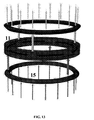
- Figure 14 shows how the non-linear element of the device participates.
- the load distribution is kept uniform during the whole process due to the continuity of the cylinder/elastic material system. In this manner the overflow effects that would be generated on the adjacent structures by the linear element are partly corrected.
- the V-shape or H-shape of the horizontal levels of slots 14 are those which provide the confinement in a simple and natural manner.
- slot 14 allows, at the same time, reacting with loads parallel and normal to the surface of the elastic material 15, thus achieving that the latter works in shear, dissipating energy and dampening, and in compression providing additional rigidity.
- each one of the slots 14 distributed in layers.
- the shape of the slot 14 and the course followed by the slots 14 when following the perimeter of the cylinder 11 may be straight, for example. In this case the shear and compressive deformations of the elastic material 15 are completely decoupled.
- slots 14 may be used with other types of shapes, such as oval slots, where the axis of greater dimension is perpendicular to the axis of the straight cylinder 11, the smaller axis of the oval being parallel to the axis of revolution of the cylinder 11, not shown.
- the mechanical features of the attenuating device may be easily varied to adapt to different requirements that may be demanded of it. For this it will be sufficient to adjust the size of the slots 14 to a compromise between the filtering requirements and the mechanical requirements.
Landscapes
- Engineering & Computer Science (AREA)
- General Engineering & Computer Science (AREA)
- Mechanical Engineering (AREA)
- Aviation & Aerospace Engineering (AREA)
- Acoustics & Sound (AREA)
- Physics & Mathematics (AREA)
- Chemical & Material Sciences (AREA)
- Combustion & Propulsion (AREA)
- Remote Sensing (AREA)
- Vibration Prevention Devices (AREA)
- Buildings Adapted To Withstand Abnormal External Influences (AREA)
- Transmitters (AREA)
- Control Of Motors That Do Not Use Commutators (AREA)
- Surface Acoustic Wave Elements And Circuit Networks Thereof (AREA)
- Vibration Dampers (AREA)
- Surgical Instruments (AREA)
- Noodles (AREA)
- Seal Device For Vehicle (AREA)
Applications Claiming Priority (1)
| Application Number | Priority Date | Filing Date | Title |
|---|---|---|---|
| PCT/ES2002/000577 WO2004050481A1 (fr) | 2002-12-04 | 2002-12-04 | Dispositif d'attenuation |
Publications (2)
| Publication Number | Publication Date |
|---|---|
| EP1568608A1 true EP1568608A1 (fr) | 2005-08-31 |
| EP1568608B1 EP1568608B1 (fr) | 2008-06-18 |
Family
ID=32405867
Family Applications (1)
| Application Number | Title | Priority Date | Filing Date |
|---|---|---|---|
| EP02793142A Expired - Lifetime EP1568608B1 (fr) | 2002-12-04 | 2002-12-04 | Dispositif d'attenuation |
Country Status (8)
| Country | Link |
|---|---|
| US (1) | US20060145026A1 (fr) |
| EP (1) | EP1568608B1 (fr) |
| JP (1) | JP4339796B2 (fr) |
| AT (1) | ATE398574T1 (fr) |
| AU (1) | AU2002358821A1 (fr) |
| DE (1) | DE60227201D1 (fr) |
| ES (1) | ES2307813T3 (fr) |
| WO (1) | WO2004050481A1 (fr) |
Families Citing this family (4)
| Publication number | Priority date | Publication date | Assignee | Title |
|---|---|---|---|---|
| JP2012131410A (ja) * | 2010-12-22 | 2012-07-12 | Mitsubishi Heavy Ind Ltd | アダプタおよびペイロード打ち上げ用ロケット |
| EP3312097B1 (fr) * | 2015-06-16 | 2019-03-27 | Airbus Defence and Space, S.A. | Atténuateur passif léger pour aéronefs spatiaux |
| US10562650B2 (en) * | 2017-06-28 | 2020-02-18 | The Boeing Company | Corrugated payload adaptor structure |
| DE102018114583A1 (de) | 2018-06-18 | 2019-12-19 | Nemos Gmbh | Anordnung zur Übertragung von Torsionsmomenten, insbesondere als Torsionsfeder oder Antriebswelle aus Faserverbundwerkstoffen zur Erzielung einer hohen spezifischen Materialausnutzung |
Family Cites Families (13)
| Publication number | Priority date | Publication date | Assignee | Title |
|---|---|---|---|---|
| US1822026A (en) * | 1929-08-02 | 1931-09-08 | Trevoe G Murton | Vibration damper |
| US2386463A (en) * | 1943-11-06 | 1945-10-09 | Us Rubber Co | Resilient mounting |
| GB582469A (en) * | 1944-05-22 | 1946-11-18 | Andre Rubber Co | Improvements in or relating to resilient mountings |
| IT515740A (fr) * | 1953-01-16 | |||
| FR2050235A1 (en) * | 1969-07-04 | 1971-04-02 | Sud Aviation | Expanded polystyrene shock absorbant - instrument mounting for space craft |
| US4063787A (en) * | 1977-02-03 | 1977-12-20 | Thiokol Corporation | Cylindrical, flexible bearings |
| FR2715991B1 (fr) * | 1994-02-09 | 1996-04-12 | Michel Bruas | Plot de suspension destiné à être interposé entre deux éléments, notamment entre un bâti et une cuve de conteneur. |
| FR2730973B1 (fr) * | 1995-02-28 | 1997-05-16 | Peugeot | Articulation elastique notamment pour un train roulant de vehicule automobile |
| US5878980A (en) * | 1997-02-05 | 1999-03-09 | Hughes Electronics Corporation | Attenuation ring |
| US5998627A (en) * | 1997-08-04 | 1999-12-07 | Albemarle Corporation | Preparation and uses of hydrocarbylnitrones |
| ES2166234B1 (es) * | 1998-11-18 | 2003-02-16 | Eads Constr Aeronauticas Sa | Un sistema de modificacion de las propiedades de rigidez/amortiguacion de uniones estructurales. |
| FR2800351B1 (fr) * | 1999-10-28 | 2002-01-04 | Cit Alcatel | Attenuateur de chocs pour pied de gerbage |
| US6609681B2 (en) * | 2001-07-05 | 2003-08-26 | The Boeing Company | Method and apparatus for damping vibration |
-
2002
- 2002-12-04 WO PCT/ES2002/000577 patent/WO2004050481A1/fr not_active Ceased
- 2002-12-04 ES ES02793142T patent/ES2307813T3/es not_active Expired - Lifetime
- 2002-12-04 DE DE60227201T patent/DE60227201D1/de not_active Expired - Lifetime
- 2002-12-04 AT AT02793142T patent/ATE398574T1/de not_active IP Right Cessation
- 2002-12-04 EP EP02793142A patent/EP1568608B1/fr not_active Expired - Lifetime
- 2002-12-04 AU AU2002358821A patent/AU2002358821A1/en not_active Abandoned
- 2002-12-04 JP JP2004556348A patent/JP4339796B2/ja not_active Expired - Fee Related
- 2002-12-04 US US10/536,929 patent/US20060145026A1/en not_active Abandoned
Non-Patent Citations (1)
| Title |
|---|
| See references of WO2004050481A1 * |
Also Published As
| Publication number | Publication date |
|---|---|
| EP1568608B1 (fr) | 2008-06-18 |
| WO2004050481A1 (fr) | 2004-06-17 |
| ES2307813T3 (es) | 2008-12-01 |
| JP4339796B2 (ja) | 2009-10-07 |
| US20060145026A1 (en) | 2006-07-06 |
| JP2006508851A (ja) | 2006-03-16 |
| DE60227201D1 (de) | 2008-07-31 |
| AU2002358821A1 (en) | 2004-06-23 |
| ATE398574T1 (de) | 2008-07-15 |
Similar Documents
| Publication | Publication Date | Title |
|---|---|---|
| EP1948878B1 (fr) | Structure avec amortissage augmenté au moyen d'amortisseurs à configuration en fourche | |
| US3088561A (en) | Damped structures | |
| KR101550475B1 (ko) | 탄성중합체를 기반으로 하는, 진동 및 충격에 대한 다축식 차단용 모듈형 장치 | |
| US20080048069A1 (en) | Uncoupled vibrion attenuation/isolation devices | |
| JP5981559B2 (ja) | 振動絶縁システム及び方法 | |
| Ma et al. | A reusable metastructure for tri-directional energy dissipation | |
| Asiri et al. | Periodic struts for gearbox support system | |
| US5833038A (en) | Method and apparatus for broadband earthquake resistant foundation with variable stiffness | |
| KR20080085180A (ko) | 엘라스토머계 모듈형 다축 진동/충격 차단 장치 | |
| EP1568608B1 (fr) | Dispositif d'attenuation | |
| CA2989385C (fr) | Attenuateur passif leger pour aeronefs spatiaux | |
| CN118008996B (zh) | 航天器控制力矩陀螺变阻尼变刚度、宽频带并联隔振系统 | |
| CN115637791A (zh) | 一种具有低宽频带隙特性的弧形超阻尼隔振装置 | |
| CN115807492A (zh) | 一种碰撞双质量多阶调谐减振系统 | |
| CN109826087B (zh) | 一种缓冲消能的桥梁抗震装置 | |
| Yao et al. | Experimental and theoretical research on the impact resistance performance of thin-walled viscoelastic vibration isolation devices | |
| JP7536542B2 (ja) | 建物の構築方法 | |
| JP5030445B2 (ja) | 免震装置 | |
| AU2021361097B2 (en) | Structural bearing for protecting structures against shocks | |
| JPH01102182A (ja) | 耐震壁 | |
| JPH04337130A (ja) | 防振支承 | |
| JP3935337B2 (ja) | 分離型ショックマウント | |
| JPH09210122A (ja) | 免震アイソレーター | |
| JPH01312133A (ja) | 構造物の鉛直振動吸収装置 | |
| JPH0658008A (ja) | 三次元免震装置 |
Legal Events
| Date | Code | Title | Description |
|---|---|---|---|
| PUAI | Public reference made under article 153(3) epc to a published international application that has entered the european phase |
Free format text: ORIGINAL CODE: 0009012 |
|
| 17P | Request for examination filed |
Effective date: 20050527 |
|
| AK | Designated contracting states |
Kind code of ref document: A1 Designated state(s): AT BE BG CH CY CZ DE DK EE ES FI FR GB GR IE IT LI LU MC NL PT SE SI SK TR |
|
| AX | Request for extension of the european patent |
Extension state: AL LT LV MK RO |
|
| DAX | Request for extension of the european patent (deleted) | ||
| 17Q | First examination report despatched |
Effective date: 20070119 |
|
| GRAP | Despatch of communication of intention to grant a patent |
Free format text: ORIGINAL CODE: EPIDOSNIGR1 |
|
| RIN1 | Information on inventor provided before grant (corrected) |
Inventor name: LANCHO DONCEL, MIGUEL |
|
| GRAS | Grant fee paid |
Free format text: ORIGINAL CODE: EPIDOSNIGR3 |
|
| GRAA | (expected) grant |
Free format text: ORIGINAL CODE: 0009210 |
|
| AK | Designated contracting states |
Kind code of ref document: B1 Designated state(s): AT BE BG CH CY CZ DE DK EE ES FI FR GB GR IE IT LI LU MC NL PT SE SI SK TR |
|
| REG | Reference to a national code |
Ref country code: GB Ref legal event code: FG4D |
|
| REF | Corresponds to: |
Ref document number: 60227201 Country of ref document: DE Date of ref document: 20080731 Kind code of ref document: P |
|
| REG | Reference to a national code |
Ref country code: CH Ref legal event code: EP |
|
| REG | Reference to a national code |
Ref country code: IE Ref legal event code: FG4D |
|
| REG | Reference to a national code |
Ref country code: SE Ref legal event code: TRGR |
|
| PG25 | Lapsed in a contracting state [announced via postgrant information from national office to epo] |
Ref country code: FI Free format text: LAPSE BECAUSE OF FAILURE TO SUBMIT A TRANSLATION OF THE DESCRIPTION OR TO PAY THE FEE WITHIN THE PRESCRIBED TIME-LIMIT Effective date: 20080618 Ref country code: SI Free format text: LAPSE BECAUSE OF FAILURE TO SUBMIT A TRANSLATION OF THE DESCRIPTION OR TO PAY THE FEE WITHIN THE PRESCRIBED TIME-LIMIT Effective date: 20080618 |
|
| PG25 | Lapsed in a contracting state [announced via postgrant information from national office to epo] |
Ref country code: NL Free format text: LAPSE BECAUSE OF FAILURE TO SUBMIT A TRANSLATION OF THE DESCRIPTION OR TO PAY THE FEE WITHIN THE PRESCRIBED TIME-LIMIT Effective date: 20080618 Ref country code: AT Free format text: LAPSE BECAUSE OF FAILURE TO SUBMIT A TRANSLATION OF THE DESCRIPTION OR TO PAY THE FEE WITHIN THE PRESCRIBED TIME-LIMIT Effective date: 20080618 |
|
| REG | Reference to a national code |
Ref country code: ES Ref legal event code: FG2A Ref document number: 2307813 Country of ref document: ES Kind code of ref document: T3 |
|
| NLV1 | Nl: lapsed or annulled due to failure to fulfill the requirements of art. 29p and 29m of the patents act | ||
| PG25 | Lapsed in a contracting state [announced via postgrant information from national office to epo] |
Ref country code: PT Free format text: LAPSE BECAUSE OF FAILURE TO SUBMIT A TRANSLATION OF THE DESCRIPTION OR TO PAY THE FEE WITHIN THE PRESCRIBED TIME-LIMIT Effective date: 20081118 Ref country code: CZ Free format text: LAPSE BECAUSE OF FAILURE TO SUBMIT A TRANSLATION OF THE DESCRIPTION OR TO PAY THE FEE WITHIN THE PRESCRIBED TIME-LIMIT Effective date: 20080618 |
|
| PG25 | Lapsed in a contracting state [announced via postgrant information from national office to epo] |
Ref country code: SK Free format text: LAPSE BECAUSE OF FAILURE TO SUBMIT A TRANSLATION OF THE DESCRIPTION OR TO PAY THE FEE WITHIN THE PRESCRIBED TIME-LIMIT Effective date: 20080618 Ref country code: BE Free format text: LAPSE BECAUSE OF FAILURE TO SUBMIT A TRANSLATION OF THE DESCRIPTION OR TO PAY THE FEE WITHIN THE PRESCRIBED TIME-LIMIT Effective date: 20080618 |
|
| PLBE | No opposition filed within time limit |
Free format text: ORIGINAL CODE: 0009261 |
|
| STAA | Information on the status of an ep patent application or granted ep patent |
Free format text: STATUS: NO OPPOSITION FILED WITHIN TIME LIMIT |
|
| PG25 | Lapsed in a contracting state [announced via postgrant information from national office to epo] |
Ref country code: BG Free format text: LAPSE BECAUSE OF FAILURE TO SUBMIT A TRANSLATION OF THE DESCRIPTION OR TO PAY THE FEE WITHIN THE PRESCRIBED TIME-LIMIT Effective date: 20080918 Ref country code: DK Free format text: LAPSE BECAUSE OF FAILURE TO SUBMIT A TRANSLATION OF THE DESCRIPTION OR TO PAY THE FEE WITHIN THE PRESCRIBED TIME-LIMIT Effective date: 20080618 Ref country code: EE Free format text: LAPSE BECAUSE OF FAILURE TO SUBMIT A TRANSLATION OF THE DESCRIPTION OR TO PAY THE FEE WITHIN THE PRESCRIBED TIME-LIMIT Effective date: 20080618 |
|
| 26N | No opposition filed |
Effective date: 20090319 |
|
| PG25 | Lapsed in a contracting state [announced via postgrant information from national office to epo] |
Ref country code: MC Free format text: LAPSE BECAUSE OF NON-PAYMENT OF DUE FEES Effective date: 20081231 |
|
| REG | Reference to a national code |
Ref country code: CH Ref legal event code: PL |
|
| REG | Reference to a national code |
Ref country code: IE Ref legal event code: MM4A |
|
| PG25 | Lapsed in a contracting state [announced via postgrant information from national office to epo] |
Ref country code: IE Free format text: LAPSE BECAUSE OF NON-PAYMENT OF DUE FEES Effective date: 20081204 Ref country code: LI Free format text: LAPSE BECAUSE OF NON-PAYMENT OF DUE FEES Effective date: 20081231 Ref country code: CH Free format text: LAPSE BECAUSE OF NON-PAYMENT OF DUE FEES Effective date: 20081231 |
|
| PG25 | Lapsed in a contracting state [announced via postgrant information from national office to epo] |
Ref country code: LU Free format text: LAPSE BECAUSE OF NON-PAYMENT OF DUE FEES Effective date: 20081204 Ref country code: CY Free format text: LAPSE BECAUSE OF FAILURE TO SUBMIT A TRANSLATION OF THE DESCRIPTION OR TO PAY THE FEE WITHIN THE PRESCRIBED TIME-LIMIT Effective date: 20080618 |
|
| PG25 | Lapsed in a contracting state [announced via postgrant information from national office to epo] |
Ref country code: TR Free format text: LAPSE BECAUSE OF FAILURE TO SUBMIT A TRANSLATION OF THE DESCRIPTION OR TO PAY THE FEE WITHIN THE PRESCRIBED TIME-LIMIT Effective date: 20080618 |
|
| PG25 | Lapsed in a contracting state [announced via postgrant information from national office to epo] |
Ref country code: GR Free format text: LAPSE BECAUSE OF FAILURE TO SUBMIT A TRANSLATION OF THE DESCRIPTION OR TO PAY THE FEE WITHIN THE PRESCRIBED TIME-LIMIT Effective date: 20080919 |
|
| PGFP | Annual fee paid to national office [announced via postgrant information from national office to epo] |
Ref country code: GB Payment date: 20121120 Year of fee payment: 11 Ref country code: SE Payment date: 20121129 Year of fee payment: 11 Ref country code: IT Payment date: 20121221 Year of fee payment: 11 |
|
| PGFP | Annual fee paid to national office [announced via postgrant information from national office to epo] |
Ref country code: FR Payment date: 20130104 Year of fee payment: 11 |
|
| PGFP | Annual fee paid to national office [announced via postgrant information from national office to epo] |
Ref country code: DE Payment date: 20130131 Year of fee payment: 11 |
|
| PGFP | Annual fee paid to national office [announced via postgrant information from national office to epo] |
Ref country code: ES Payment date: 20131226 Year of fee payment: 12 |
|
| REG | Reference to a national code |
Ref country code: DE Ref legal event code: R119 Ref document number: 60227201 Country of ref document: DE |
|
| REG | Reference to a national code |
Ref country code: SE Ref legal event code: EUG |
|
| GBPC | Gb: european patent ceased through non-payment of renewal fee |
Effective date: 20131204 |
|
| PG25 | Lapsed in a contracting state [announced via postgrant information from national office to epo] |
Ref country code: SE Free format text: LAPSE BECAUSE OF NON-PAYMENT OF DUE FEES Effective date: 20131205 |
|
| REG | Reference to a national code |
Ref country code: FR Ref legal event code: ST Effective date: 20140829 |
|
| REG | Reference to a national code |
Ref country code: DE Ref legal event code: R119 Ref document number: 60227201 Country of ref document: DE Effective date: 20140701 |
|
| PG25 | Lapsed in a contracting state [announced via postgrant information from national office to epo] |
Ref country code: DE Free format text: LAPSE BECAUSE OF NON-PAYMENT OF DUE FEES Effective date: 20140701 |
|
| PG25 | Lapsed in a contracting state [announced via postgrant information from national office to epo] |
Ref country code: GB Free format text: LAPSE BECAUSE OF NON-PAYMENT OF DUE FEES Effective date: 20131204 Ref country code: FR Free format text: LAPSE BECAUSE OF NON-PAYMENT OF DUE FEES Effective date: 20131231 |
|
| PG25 | Lapsed in a contracting state [announced via postgrant information from national office to epo] |
Ref country code: IT Free format text: LAPSE BECAUSE OF NON-PAYMENT OF DUE FEES Effective date: 20131231 |
|
| REG | Reference to a national code |
Ref country code: ES Ref legal event code: FD2A Effective date: 20160127 |
|
| PG25 | Lapsed in a contracting state [announced via postgrant information from national office to epo] |
Ref country code: ES Free format text: LAPSE BECAUSE OF NON-PAYMENT OF DUE FEES Effective date: 20141205 |
|
| PG25 | Lapsed in a contracting state [announced via postgrant information from national office to epo] |
Ref country code: IT Free format text: LAPSE BECAUSE OF NON-PAYMENT OF DUE FEES Effective date: 20131204 |