EP1568625B1 - Machine d'inspection avec un dispositif pour le transport d'articles creux - Google Patents
Machine d'inspection avec un dispositif pour le transport d'articles creux Download PDFInfo
- Publication number
- EP1568625B1 EP1568625B1 EP05003613A EP05003613A EP1568625B1 EP 1568625 B1 EP1568625 B1 EP 1568625B1 EP 05003613 A EP05003613 A EP 05003613A EP 05003613 A EP05003613 A EP 05003613A EP 1568625 B1 EP1568625 B1 EP 1568625B1
- Authority
- EP
- European Patent Office
- Prior art keywords
- machine according
- belts
- conveying
- support ring
- belt
- Prior art date
- Legal status (The legal status is an assumption and is not a legal conclusion. Google has not performed a legal analysis and makes no representation as to the accuracy of the status listed.)
- Expired - Lifetime
Links
- 238000007689 inspection Methods 0.000 title claims abstract description 51
- 239000004033 plastic Substances 0.000 claims description 4
- 229920003023 plastic Polymers 0.000 claims description 4
- 238000004519 manufacturing process Methods 0.000 claims 1
- 238000003384 imaging method Methods 0.000 description 3
- 238000000034 method Methods 0.000 description 3
- 235000013361 beverage Nutrition 0.000 description 2
- 230000000694 effects Effects 0.000 description 2
- 229920000139 polyethylene terephthalate Polymers 0.000 description 2
- 239000005020 polyethylene terephthalate Substances 0.000 description 2
- 238000005085 air analysis Methods 0.000 description 1
- 238000007664 blowing Methods 0.000 description 1
- 150000001875 compounds Chemical class 0.000 description 1
- 230000002950 deficient Effects 0.000 description 1
- 230000001419 dependent effect Effects 0.000 description 1
- 238000011161 development Methods 0.000 description 1
- 230000018109 developmental process Effects 0.000 description 1
- 229910052736 halogen Inorganic materials 0.000 description 1
- 150000002367 halogens Chemical class 0.000 description 1
- 238000005286 illumination Methods 0.000 description 1
- 238000002347 injection Methods 0.000 description 1
- 239000007924 injection Substances 0.000 description 1
- -1 polyethylene terephthalate Polymers 0.000 description 1
- 239000000243 solution Substances 0.000 description 1
- 229920001169 thermoplastic Polymers 0.000 description 1
- 239000004416 thermosoftening plastic Substances 0.000 description 1
Images


Classifications
-
- B—PERFORMING OPERATIONS; TRANSPORTING
- B29—WORKING OF PLASTICS; WORKING OF SUBSTANCES IN A PLASTIC STATE IN GENERAL
- B29C—SHAPING OR JOINING OF PLASTICS; SHAPING OF MATERIAL IN A PLASTIC STATE, NOT OTHERWISE PROVIDED FOR; AFTER-TREATMENT OF THE SHAPED PRODUCTS, e.g. REPAIRING
- B29C49/00—Blow-moulding, i.e. blowing a preform or parison to a desired shape within a mould; Apparatus therefor
- B29C49/42—Component parts, details or accessories; Auxiliary operations
- B29C49/4205—Handling means, e.g. transfer, loading or discharging means
- B29C49/42093—Transporting apparatus, e.g. slides, wheels or conveyors
-
- B—PERFORMING OPERATIONS; TRANSPORTING
- B29—WORKING OF PLASTICS; WORKING OF SUBSTANCES IN A PLASTIC STATE IN GENERAL
- B29C—SHAPING OR JOINING OF PLASTICS; SHAPING OF MATERIAL IN A PLASTIC STATE, NOT OTHERWISE PROVIDED FOR; AFTER-TREATMENT OF THE SHAPED PRODUCTS, e.g. REPAIRING
- B29C49/00—Blow-moulding, i.e. blowing a preform or parison to a desired shape within a mould; Apparatus therefor
- B29C49/42—Component parts, details or accessories; Auxiliary operations
- B29C49/78—Measuring, controlling or regulating
- B29C49/80—Testing, e.g. for leaks
-
- B—PERFORMING OPERATIONS; TRANSPORTING
- B65—CONVEYING; PACKING; STORING; HANDLING THIN OR FILAMENTARY MATERIAL
- B65G—TRANSPORT OR STORAGE DEVICES, e.g. CONVEYORS FOR LOADING OR TIPPING, SHOP CONVEYOR SYSTEMS OR PNEUMATIC TUBE CONVEYORS
- B65G15/00—Conveyors having endless load-conveying surfaces, i.e. belts and like continuous members, to which tractive effort is transmitted by means other than endless driving elements of similar configuration
- B65G15/10—Conveyors having endless load-conveying surfaces, i.e. belts and like continuous members, to which tractive effort is transmitted by means other than endless driving elements of similar configuration comprising two or more co-operating endless surfaces with parallel longitudinal axes, or a multiplicity of parallel elements, e.g. ropes defining an endless surface
- B65G15/12—Conveyors having endless load-conveying surfaces, i.e. belts and like continuous members, to which tractive effort is transmitted by means other than endless driving elements of similar configuration comprising two or more co-operating endless surfaces with parallel longitudinal axes, or a multiplicity of parallel elements, e.g. ropes defining an endless surface with two or more endless belts
- B65G15/14—Conveyors having endless load-conveying surfaces, i.e. belts and like continuous members, to which tractive effort is transmitted by means other than endless driving elements of similar configuration comprising two or more co-operating endless surfaces with parallel longitudinal axes, or a multiplicity of parallel elements, e.g. ropes defining an endless surface with two or more endless belts the load being conveyed between the belts
-
- G—PHYSICS
- G01—MEASURING; TESTING
- G01N—INVESTIGATING OR ANALYSING MATERIALS BY DETERMINING THEIR CHEMICAL OR PHYSICAL PROPERTIES
- G01N21/00—Investigating or analysing materials by the use of optical means, i.e. using sub-millimetre waves, infrared, visible or ultraviolet light
- G01N21/84—Systems specially adapted for particular applications
- G01N21/88—Investigating the presence of flaws or contamination
- G01N21/90—Investigating the presence of flaws or contamination in a container or its contents
- G01N21/9009—Non-optical constructional details affecting optical inspection, e.g. cleaning mechanisms for optical parts, vibration reduction
-
- G—PHYSICS
- G01—MEASURING; TESTING
- G01N—INVESTIGATING OR ANALYSING MATERIALS BY DETERMINING THEIR CHEMICAL OR PHYSICAL PROPERTIES
- G01N21/00—Investigating or analysing materials by the use of optical means, i.e. using sub-millimetre waves, infrared, visible or ultraviolet light
- G01N21/84—Systems specially adapted for particular applications
- G01N21/88—Investigating the presence of flaws or contamination
- G01N21/90—Investigating the presence of flaws or contamination in a container or its contents
- G01N21/9081—Inspection especially designed for plastic containers, e.g. preforms
-
- B—PERFORMING OPERATIONS; TRANSPORTING
- B29—WORKING OF PLASTICS; WORKING OF SUBSTANCES IN A PLASTIC STATE IN GENERAL
- B29C—SHAPING OR JOINING OF PLASTICS; SHAPING OF MATERIAL IN A PLASTIC STATE, NOT OTHERWISE PROVIDED FOR; AFTER-TREATMENT OF THE SHAPED PRODUCTS, e.g. REPAIRING
- B29C49/00—Blow-moulding, i.e. blowing a preform or parison to a desired shape within a mould; Apparatus therefor
- B29C49/42—Component parts, details or accessories; Auxiliary operations
- B29C49/78—Measuring, controlling or regulating
- B29C2049/7874—Preform or article shape, weight, defect or presence
- B29C2049/7876—Defects
-
- B—PERFORMING OPERATIONS; TRANSPORTING
- B29—WORKING OF PLASTICS; WORKING OF SUBSTANCES IN A PLASTIC STATE IN GENERAL
- B29C—SHAPING OR JOINING OF PLASTICS; SHAPING OF MATERIAL IN A PLASTIC STATE, NOT OTHERWISE PROVIDED FOR; AFTER-TREATMENT OF THE SHAPED PRODUCTS, e.g. REPAIRING
- B29C49/00—Blow-moulding, i.e. blowing a preform or parison to a desired shape within a mould; Apparatus therefor
- B29C49/42—Component parts, details or accessories; Auxiliary operations
- B29C49/4205—Handling means, e.g. transfer, loading or discharging means
- B29C49/42069—Means explicitly adapted for transporting blown article
-
- B—PERFORMING OPERATIONS; TRANSPORTING
- B29—WORKING OF PLASTICS; WORKING OF SUBSTANCES IN A PLASTIC STATE IN GENERAL
- B29C—SHAPING OR JOINING OF PLASTICS; SHAPING OF MATERIAL IN A PLASTIC STATE, NOT OTHERWISE PROVIDED FOR; AFTER-TREATMENT OF THE SHAPED PRODUCTS, e.g. REPAIRING
- B29C49/00—Blow-moulding, i.e. blowing a preform or parison to a desired shape within a mould; Apparatus therefor
- B29C49/42—Component parts, details or accessories; Auxiliary operations
- B29C49/42378—Handling malfunction
- B29C49/4238—Ejecting defective preforms or products
-
- B—PERFORMING OPERATIONS; TRANSPORTING
- B65—CONVEYING; PACKING; STORING; HANDLING THIN OR FILAMENTARY MATERIAL
- B65G—TRANSPORT OR STORAGE DEVICES, e.g. CONVEYORS FOR LOADING OR TIPPING, SHOP CONVEYOR SYSTEMS OR PNEUMATIC TUBE CONVEYORS
- B65G2201/00—Indexing codes relating to handling devices, e.g. conveyors, characterised by the type of product or load being conveyed or handled
- B65G2201/02—Articles
- B65G2201/0235—Containers
- B65G2201/0244—Bottles
- B65G2201/0247—Suspended bottles
Definitions
- the invention relates to an inspection machine with inspection units and with a device for transporting hollow bodies, according to the preamble of claim 1.
- Such inspection machines are used in industries that use hollow bodies to store their products. Such inspection machines find particular application in the food industry, especially in the beverage industry. Here they are used, inter alia, to plastic preforms, from which later the hollow body arise, for any errors, such. To investigate irregularities in the mouth diameter or damage.
- the plastic hollow bodies mentioned are often thermoplastic hollow plastic bodies, preferably PET bottles (polyethylene terephthalate). For inspection, they are transported by means of a transport device through the inspection machine, which may contain one or more inspection units.
- the inspection equipment such as a CCD camera and a lighting unit are located above and / or below the belt return. From this arrangement, there is the problem that the inspection units are relatively far away from the preforms, since the returning run of the conveyor belt runs between the preforms and the inspection units. In addition, the available field of view is very limited. Therefore, at high throughput speeds through the inspection area, inadequate inspection results regarding the quality of the preforms may occur. However, the quality of the preforms has a decisive effect on the quality of the final products or on the performance of the machines that process the preforms (such as a stretch blow molder).
- the invention is therefore based on the object to provide an inspection machine with good inspection options despite compact volume.
- the hollow bodies are fed in the direction of an inspection machine, at whose entrance they are detected by four transport elements on the support ring and transported through the inspection machine.
- at least one of the transport elements is an endless belt, which rotates in a circulation plane over deflection or drive rollers.
- At least one of these belts is drivable to ensure forward movement within the inspection machine.
- the other belts are either not driven independently or by a connection to the first belt.
- the compounds are adjustable cardan shafts. Also conceivable is a separate drive for each belt.
- At least one belt can be driven separately and thereby also at different speeds relative to one of the other belts.
- a rotation of the preform about its longitudinal axis can be generated.
- the circulating planes in which the belts revolve are arranged at an angle greater than 0 ° and less than 90 ° with respect to the support ring plane.
- the angle is between 20 ° and 80 °, preferably between 55 ° and 65 °.
- This oblique arrangement creates above or below the preform at least one extended free space in the inspection machine, in the various inspection machine or components thereof such as a camera (eg CCD camera), sensors (eg for air analysis in the preform) or lighting units (eg toroidal Halogen lamp under the camera or lamp under the preform) can be introduced.
- a camera eg CCD camera
- sensors eg for air analysis in the preform
- lighting units eg toroidal Halogen lamp under the camera or lamp under the preform
- the inspection units very close to the preform to be inspected, in particular its mouth, in order to achieve the best possible inspection results, above all in the case of imaging inspection methods.
- large-area images of the areas of interest with high resolution can be achieved.
- the inspection of the critical areas e.g., orifice or gate
- a recording is made when the passing longitudinal axis of the preform is aligned with the perpendicular to the support ring plane of the preform camera axis.
- the preform is illuminated almost simultaneously by the illumination device.
- the inspection machine has four belt-shaped transport devices. In this form it is possible that all four angles between the support ring plane and the circulation planes are the same.
- the transport device is adjustable so that it can accommodate both preforms with different support ring thicknesses as well as preforms with different diameters.
- the adjustment may be both mechanical, such as via a crank and a spindle, as well as electrically, such as via a manual or program controlled servomotor or otherwise, such as pneumatically.
- the gap between the two offset transversely to the longitudinal axis of the preform transport element pairs that grip the preform on the support ring is preferably smaller than the diameter of the preform. In this way, a frictional transport is ensured also with respect to the preform width.
- spring-loaded pressure rollers are provided which press the belts in the direction of the support ring.
- spring-loaded pressure rollers instead of the spring-loaded pressure rollers.
- fixed and adjustable pressure rollers instead of the spring-loaded pressure rollers.
- a sliding strip or the like could be used.
- the transport of the hollow body or preform by the inspection machine is substantially linear and horizontal.
- it can easily be retrofitted without altering the height levels in an existing line, for example, between blowing and filling machine.
- preforms are faulty, they must be sorted out and withdrawn from further use. For this reason, after the inspection part of the machine is a controllable sorting device for unusable preforms.
- the ejection device can be integrated into the inspection machine as well as connected to the outlet-side transport region of the machine. There are known in the art various ejection devices, which is why they will not be described in detail here.
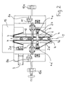
- FIGS. 1, 2 and 3 an inspection machine is shown in which four transport elements are provided, each formed as endless belts 2a, 2b, 2c, 2d.
- the four belts are arranged symmetrically both with respect to a support ring plane A and with respect to the plane spanned by the longitudinal axis of a preform and the transport direction, and in each case have the same angles ⁇ a, ⁇ b, ⁇ c, ⁇ d with respect to the support ring plane A.
- the circulation planes B1-B4 are substantially straight and run parallel to the carrier plate pairs 6a-6d. Between the legs of this X arrangement, there is sufficient space above and below the preform 1 for inspection units 12, 13, 14. With the aid of a camera 12, the mouth areas and possibly the injection points of the preforms are inspected by an imaging method.
- the preforms 1 are illuminated by means of a lamp 13 which is attached laterally and whose light is redirected to the preform 1 by means of a semipermeable mirror 14.
- the belt 2c and 2d are adjusted by tension rollers 7 in their clamping force. But it is also possible to tighten all belts of the machine 2a-2e by tension rollers 7.
- the belts 2a, 2b, 2c, 2d, 2e receiving drive wheels 4a ', 4a and the guide rollers 4 are rotatably mounted on support plates 6a-6d, which in turn are mounted on a base frame 8a-8d. For orientation, the base frame 8a-8d runs in profile rails 9.
- the two parts of the base frame 8c and 8d, and thus also attached to these belts 2a and 2b, are vertically adjustable by an adjusting device 10b, so that the vertical gap S 'between the upper Support plate pair 6a, 6c and the lower support plate pair 6b, 6d is variable.
- the adjusting device 10b consists of a spindle and a crank. Upon actuation of the crank, the upper pair of carrier plates 6a and 6c with all elements attached thereto, such as belts 2a, 2b, or drive roller 4a ', are moved along the profile rails 11.
- this vertical gap S ' is located during the transport of preforms 1 of the support ring 1a.
- the adjustment of the vertical gap S ' is present because the inspection machine can accommodate different preforms 1 with different support ring thicknesses 1a during a grade change.
- the adjustment of the vertical gap becomes S 'made so that it is slightly smaller than the support ring thickness 1a of the preform 1 to be transported in order to ensure a frictional engagement of the belt 2a, 2b, 2c and 2d on the support ring 1a.
- the horizontal gap S can be adjusted by means of an adjusting device 10a, which also consists of a crank and a threaded spindle here.
- the left 6c, 6d and the right pair of carrier plates 6a, 6c is preferably adjusted so that the horizontal gap S between them is slightly smaller than the diameter of the preforms 1 to be transported, in order to achieve a frictional transport here as well. If one wishes to convey through the inspection machine hollow body 1 with a different orifice diameter, the adjusting device 10a is actuated such that the base frame halves 8a, 8b move horizontally transversely to the transport direction apart or toward one another in order to make the gap S larger or smaller.
- the propeller shafts 5, which transmit the driving force from the motor 3 and the drive roller 4a 'to the other drive rollers 4a, are designed to be longitudinally adjustable. This is necessary because in the horizontal and vertical adjustment of the belt (2a-2d) for the purpose of receiving different preforms 1 with different mouth and Tragringgeometrien, also the distances between the drive rollers 4a 'and 4a change.
- the belts 2a, 2b, 2c and 2d are equipped with a specific geometry in order to lie as well as possible on the support ring 1a of the preform 1 (see FIG. 3).
- the two lower belts 2c and 2d have surfaces at right angles to each other, which are in engagement with the preform 1 on the underside of the support ring, where this also forms a right angle between the support ring A and its longitudinal axis.
- the two upper belts 2a and 2b run on the side facing away from the preform 1 side parallel to the support ring plane A and the lower belt 2c and 2d.
- the belts 2a and 2b run at an angle corresponding to that between the support ring plane A and the upper part of the support ring.
- the inner sides of the belts 2a-2d that is to say the sides on which the belts engage with the deflection 4 or drive rollers 4a and 4a ', are designed as toothed belts. For the sake of clarity, this is not shown here.
- the timing belt side of belts 2a-2d is made of HTD while the applied profiled side is made of Linatex®.
- an ejecting device 15 which removes defective or no longer usable preforms 1 for further use in the subsequent machine cycle.
- This is an arbitrary commercial ejection device 15, which is not shown in greater detail here for the sake of clarity.
Landscapes
- Engineering & Computer Science (AREA)
- Mechanical Engineering (AREA)
- Manufacturing & Machinery (AREA)
- Biochemistry (AREA)
- General Physics & Mathematics (AREA)
- Life Sciences & Earth Sciences (AREA)
- Chemical & Material Sciences (AREA)
- Analytical Chemistry (AREA)
- Physics & Mathematics (AREA)
- General Health & Medical Sciences (AREA)
- Health & Medical Sciences (AREA)
- Immunology (AREA)
- Pathology (AREA)
- Blow-Moulding Or Thermoforming Of Plastics Or The Like (AREA)
- Separation Using Semi-Permeable Membranes (AREA)
- Investigating Materials By The Use Of Optical Means Adapted For Particular Applications (AREA)
- Structure Of Belt Conveyors (AREA)
Claims (18)
- Machine d'inspection comportant des unités d'inspection (12, 13, 14) d'articles creux (1) présentant un anneau porteur (1a), et un dispositif de transport des articles creux (1) constitué par quatre éléments de transport (2a à 2d) déplaçant les articles creux (1) et parcourant un circuit sans fin dans des plans de circulation (B1 à B4), au moins un des éléments étant entraîné et les éléments par paire respective saisissant l'anneau porteur (1a) sur des côtés opposés par le haut et par le bas,
caractérisée en ce que
les quatre plans de circulation (B1 à B4) sont orientés en s'écartant de chaque côté de l'article creux (1), selon un angle (αa-αd) supérieur à 0° et inférieur à 90° par rapport à un plan d'anneau porteur (A), et sont orientés par rapport à la direction de transport (T) en formant essentiellement un montage en X. - Machine selon la revendication 1,
caractérisée en ce qu'
au moins un élément de transport (2a à 2d) entraîné consiste en une courroie. - Machine selon les revendications 1 et 2,
caractérisée en ce qu'
au moins un élément de transport (2a à 2d) entraîné est appliqué sur des poulies de renvoi (4) et des poulies d'entraînement (4a, 4a'). - Machine selon l'une quelconque des revendications précédentes, caractérisée en ce qu'
au moins deux éléments de transport (2a à 2d) sont des courroies que l'on peut entraîner. - Machine selon la revendication 4,
caractérisée en ce qu'
au moins un des éléments de transport (2a à 2d) peut être entraîné séparément. - Machine selon l'une au moins des revendications 1 à 5,
caractérisée en ce que
les angles (αa-αd) formés par les plans de circulation (B1 à B4) et le plan de l'anneau porteur (A) sont identiques. - Machine selon l'une au moins des revendications 1 à 6,
caractérisée en ce que
les angles (αa-αd) sont compris entre 20° et 80°, de préférence entre 55° et 65°. - Machine selon au moins l'une quelconque des revendications précédentes,
caractérisée en ce que
les quatre éléments de transport (2a à 2d) sont des courroies. - Machine selon la revendication 8,
caractérisée en ce qu'
au moins une paire de courroies (2a, 2b ; 2c, 2d) saisissant l'anneau porteur (1a) par le haut et par le bas est mobile verticalement afin de pouvoir faire varier un interstice S' dans lequel se trouve l'anneau porteur (1a) lors du transport des articles creux (1). - Machine selon la revendication 9,
caractérisée en ce que
l'interstice S' est plus mince que l'épaisseur de l'anneau porteur (1a) de l'article creux (1) et les courroies (2a à 2b) saisissent ainsi l'anneau porteur (1a) par frottement. - Machine selon au moins l'une quelconque des revendications précédentes,
caractérisée en ce qu'
au moins une paire de courroies (2a, 2b ; 2c, 2d) saisissant l'anneau porteur (1a) par le côté est mobile transversalement à une direction de transport (T) afin de pouvoir recevoir des articles creux (1) de différents diamètres. - Machine selon les revendications 8 à 11,
caractérisée en ce que
les plans de circulation (B 1 à B4) sont orientés par rapport à la direction de transport (T) des articles creux (1) de manière à former un montage symétrique en X. - Machine selon au moins l'une quelconque des revendications précédentes,
caractérisée par
au moins une unité d'inspection (12, 13, 14) des articles creux (1) dans la zone de branche supérieure et/ou inférieure du montage en X. - Machine selon au moins l'une quelconque des revendications précédentes,
caractérisée en ce que
le transport des articles creux (1) s'effectue de manière essentiellement linéaire et horizontale. - Machine selon au moins l'une quelconque des revendications précédentes,
caractérisée en ce que
les courroies (2a à 2d) sont entraînées chacune par un moteur (3) distinct. - Machine selon au moins l'une quelconque des revendications précédentes,
caractérisée en ce que
seule une courroie (2a) est entraînée par un moteur (3) tandis que l'entraînement des autres courroies (2b à 2d) s'effectue via des connexions (5) à la première. - Machine selon au moins l'une quelconque des revendications précédentes,
caractérisée en ce qu'
un dispositif de rejet (15) destiné aux articles creux (1) non utilisables est disposé postérieurement au trajet de transport passant par la machine d'inspection. - Machine selon au moins l'une quelconque des revendications précédentes,
caractérisée en ce que
les articles creux (1) sont des récipients, notamment des bouteilles en matière plastique ou des préformes pour la fabrication de celles-ci.
Applications Claiming Priority (2)
| Application Number | Priority Date | Filing Date | Title |
|---|---|---|---|
| DE102004009698 | 2004-02-27 | ||
| DE102004009698A DE102004009698A1 (de) | 2004-02-27 | 2004-02-27 | Inspektionsmaschine mit einer Vorrichtung zum Transportieren von Hohlkörpern |
Publications (2)
| Publication Number | Publication Date |
|---|---|
| EP1568625A1 EP1568625A1 (fr) | 2005-08-31 |
| EP1568625B1 true EP1568625B1 (fr) | 2006-08-23 |
Family
ID=34745306
Family Applications (1)
| Application Number | Title | Priority Date | Filing Date |
|---|---|---|---|
| EP05003613A Expired - Lifetime EP1568625B1 (fr) | 2004-02-27 | 2005-02-19 | Machine d'inspection avec un dispositif pour le transport d'articles creux |
Country Status (3)
| Country | Link |
|---|---|
| EP (1) | EP1568625B1 (fr) |
| AT (1) | ATE337241T1 (fr) |
| DE (2) | DE102004009698A1 (fr) |
Cited By (1)
| Publication number | Priority date | Publication date | Assignee | Title |
|---|---|---|---|---|
| US12158433B2 (en) | 2019-06-28 | 2024-12-03 | Sacmi Cooperativa Meccanici Imola Societa′ Cooperativa | Device for optical inspection of preforms |
Families Citing this family (4)
| Publication number | Priority date | Publication date | Assignee | Title |
|---|---|---|---|---|
| DE502006008394D1 (de) * | 2005-09-09 | 2011-01-05 | Sidel Participations Sas | Vorrichtung zum transportieren von gegenständen |
| DE102005060814B4 (de) * | 2005-12-20 | 2014-12-31 | Krones Aktiengesellschaft | Vorrichtung und Verfahren zum Formblasen von Behältern |
| GB2482473A (en) * | 2010-06-29 | 2012-02-08 | Constar Internat Uk Ltd | Inspection of articles |
| DE102018110803A1 (de) | 2018-05-04 | 2019-11-07 | INTRAVIS Gesellschaft für Lieferungen und Leistungen von bildgebenden und bildverarbeitenden Anlagen und Verfahren mbH | Vorrichtung zum Transport und Prüfen von Vorformlingen |
Family Cites Families (7)
| Publication number | Priority date | Publication date | Assignee | Title |
|---|---|---|---|---|
| NL8303007A (nl) * | 1983-04-22 | 1984-11-16 | Thomassen & Drijver | Inrichting voor het controleren van houders. |
| DE3515353A1 (de) * | 1985-04-27 | 1986-10-30 | Seitz Enzinger Noll Maschinenbau Ag, 6800 Mannheim | Vorrichtung zum foerdern von flaschen in haengender lage |
| NL9001589A (nl) * | 1990-07-12 | 1992-02-03 | Smit Gerardus | Transportinrichting voor flessen. |
| US5553698A (en) * | 1994-12-28 | 1996-09-10 | J And J Container Handling Systems | Conveyor belt apparatus for bottles |
| US6109426A (en) * | 1996-11-13 | 2000-08-29 | Simplimatic Engineering Company | Oriented bottle conveyor |
| JP2000168945A (ja) * | 1998-12-07 | 2000-06-20 | Kirin Techno System:Kk | プリフォーム検査用搬送装置 |
| JP2001063807A (ja) * | 1999-08-31 | 2001-03-13 | Sakamoto Engineering:Kk | 搬送装置 |
-
2004
- 2004-02-27 DE DE102004009698A patent/DE102004009698A1/de not_active Withdrawn
-
2005
- 2005-02-19 EP EP05003613A patent/EP1568625B1/fr not_active Expired - Lifetime
- 2005-02-19 DE DE502005000061T patent/DE502005000061D1/de not_active Expired - Lifetime
- 2005-02-19 AT AT05003613T patent/ATE337241T1/de active
Cited By (1)
| Publication number | Priority date | Publication date | Assignee | Title |
|---|---|---|---|---|
| US12158433B2 (en) | 2019-06-28 | 2024-12-03 | Sacmi Cooperativa Meccanici Imola Societa′ Cooperativa | Device for optical inspection of preforms |
Also Published As
| Publication number | Publication date |
|---|---|
| EP1568625A1 (fr) | 2005-08-31 |
| DE502005000061D1 (de) | 2006-10-05 |
| DE102004009698A1 (de) | 2005-09-15 |
| ATE337241T1 (de) | 2006-09-15 |
Similar Documents
| Publication | Publication Date | Title |
|---|---|---|
| DE10259589B3 (de) | Verfahren und Vorrichtung zum Herstellen von Hohlkörpern aus Kunststoff | |
| EP3678964B1 (fr) | Dispositif et procédé d'orientation de lots de produits | |
| EP2059386B1 (fr) | Dispositif et procédé de fabrication de sachets en tissu synthétique revêtu | |
| EP0996531B1 (fr) | Procede et dispositif pour produire des corps creux en matiere plastique | |
| EP3635376B1 (fr) | Dispositif et procédé de vérification de corps creux | |
| DE10154203B4 (de) | Einlaufsystem für flaschenverarbeitende Maschinen in der Getränke- und Abfülltechnik | |
| DE9007826U1 (de) | Vorrichtung zur Seitenwand- und Bodeninspektion rotationssymmetrischer Gegenstände, insbesondere Flaschen | |
| DE69718374T2 (de) | Verfahren und Vorrichtung zum geordneten Abführen von ungeordnet zugeführten Produkten | |
| DE102012102073A1 (de) | Kontrollmodul | |
| DE19737527C2 (de) | Vorrichtung zur Herstellung von Kunststoffhohlkörpern | |
| EP1568625B1 (fr) | Machine d'inspection avec un dispositif pour le transport d'articles creux | |
| DE60317990T2 (de) | Vorrichtung zur Inspektion flacher Tabletten | |
| EP3402722A1 (fr) | Système de traitement de récipients et procédé de changement du fonctionnement d'un système de traitement de récipients | |
| DE69426514T2 (de) | Anordnung zur Kontrolle von Hohlglasbehältern | |
| DE60108776T2 (de) | Vorrichtung zum kontinuierlichen Aufreihen rotationssymmetrischer Gegenstände - Verwendung zur visuellen Inspektion und Kontrolle | |
| DE202004021491U1 (de) | Inspektionsmaschine mit einer Vorrichtung zum Transportieren von Hohlkörpern | |
| AT518335B1 (de) | Verfahren zum Prüfen eines, aus Druckfolien hergestellten, spritzgussgefertigten, Behälters | |
| EP3577445B1 (fr) | Dispositif et procédé d'inspection pour l'inspection de parois latérales et de tête de fermeture de récipients | |
| DE4418359C2 (de) | Verfahren und Vorrichtung zum Ausrichten von Stückgut | |
| EP1271123A1 (fr) | Procédé et appareil pour tester la qualité d'articles ronds moulés et élastiques | |
| DE112023005593T5 (de) | Folientransportmaschine, folientransportverfahren und vorrichtung zur folienherstellung | |
| EP2808275A1 (fr) | Dispositif de convoyage pour récipients et procédé de déviation de récipients d'une première à une seconde direction de transport | |
| EP4548084B1 (fr) | Système de contrôle | |
| EP3953261B1 (fr) | Machine de bandage pour bander un produit avec une sangle | |
| DE102023133768A1 (de) | Inspektionsvorrichtung für Behälter |
Legal Events
| Date | Code | Title | Description |
|---|---|---|---|
| PUAI | Public reference made under article 153(3) epc to a published international application that has entered the european phase |
Free format text: ORIGINAL CODE: 0009012 |
|
| AK | Designated contracting states |
Kind code of ref document: A1 Designated state(s): AT BE BG CH CY CZ DE DK EE ES FI FR GB GR HU IE IS IT LI LT LU MC NL PL PT RO SE SI SK TR |
|
| AX | Request for extension of the european patent |
Extension state: AL BA HR LV MK YU |
|
| 17P | Request for examination filed |
Effective date: 20050805 |
|
| GRAP | Despatch of communication of intention to grant a patent |
Free format text: ORIGINAL CODE: EPIDOSNIGR1 |
|
| AKX | Designation fees paid |
Designated state(s): AT BE BG CH CY CZ DE DK EE ES FI FR GB GR HU IE IS IT LI LT LU MC NL PL PT RO SE SI SK TR |
|
| GRAS | Grant fee paid |
Free format text: ORIGINAL CODE: EPIDOSNIGR3 |
|
| GRAA | (expected) grant |
Free format text: ORIGINAL CODE: 0009210 |
|
| AK | Designated contracting states |
Kind code of ref document: B1 Designated state(s): AT BE BG CH CY CZ DE DK EE ES FI FR GB GR HU IE IS IT LI LT LU MC NL PL PT RO SE SI SK TR |
|
| PG25 | Lapsed in a contracting state [announced via postgrant information from national office to epo] |
Ref country code: CZ Free format text: LAPSE BECAUSE OF FAILURE TO SUBMIT A TRANSLATION OF THE DESCRIPTION OR TO PAY THE FEE WITHIN THE PRESCRIBED TIME-LIMIT Effective date: 20060823 Ref country code: PL Free format text: LAPSE BECAUSE OF FAILURE TO SUBMIT A TRANSLATION OF THE DESCRIPTION OR TO PAY THE FEE WITHIN THE PRESCRIBED TIME-LIMIT Effective date: 20060823 Ref country code: LT Free format text: LAPSE BECAUSE OF FAILURE TO SUBMIT A TRANSLATION OF THE DESCRIPTION OR TO PAY THE FEE WITHIN THE PRESCRIBED TIME-LIMIT Effective date: 20060823 Ref country code: IT Free format text: LAPSE BECAUSE OF FAILURE TO SUBMIT A TRANSLATION OF THE DESCRIPTION OR TO PAY THE FEE WITHIN THE PRESCRIBED TIME-LIMIT;WARNING: LAPSES OF ITALIAN PATENTS WITH EFFECTIVE DATE BEFORE 2007 MAY HAVE OCCURRED AT ANY TIME BEFORE 2007. THE CORRECT EFFECTIVE DATE MAY BE DIFFERENT FROM THE ONE RECORDED. Effective date: 20060823 Ref country code: IE Free format text: LAPSE BECAUSE OF FAILURE TO SUBMIT A TRANSLATION OF THE DESCRIPTION OR TO PAY THE FEE WITHIN THE PRESCRIBED TIME-LIMIT Effective date: 20060823 Ref country code: RO Free format text: LAPSE BECAUSE OF FAILURE TO SUBMIT A TRANSLATION OF THE DESCRIPTION OR TO PAY THE FEE WITHIN THE PRESCRIBED TIME-LIMIT Effective date: 20060823 Ref country code: IS Free format text: LAPSE BECAUSE OF FAILURE TO SUBMIT A TRANSLATION OF THE DESCRIPTION OR TO PAY THE FEE WITHIN THE PRESCRIBED TIME-LIMIT Effective date: 20060823 Ref country code: SI Free format text: LAPSE BECAUSE OF FAILURE TO SUBMIT A TRANSLATION OF THE DESCRIPTION OR TO PAY THE FEE WITHIN THE PRESCRIBED TIME-LIMIT Effective date: 20060823 Ref country code: NL Free format text: LAPSE BECAUSE OF FAILURE TO SUBMIT A TRANSLATION OF THE DESCRIPTION OR TO PAY THE FEE WITHIN THE PRESCRIBED TIME-LIMIT Effective date: 20060823 Ref country code: SK Free format text: LAPSE BECAUSE OF FAILURE TO SUBMIT A TRANSLATION OF THE DESCRIPTION OR TO PAY THE FEE WITHIN THE PRESCRIBED TIME-LIMIT Effective date: 20060823 Ref country code: FI Free format text: LAPSE BECAUSE OF FAILURE TO SUBMIT A TRANSLATION OF THE DESCRIPTION OR TO PAY THE FEE WITHIN THE PRESCRIBED TIME-LIMIT Effective date: 20060823 |
|
| REG | Reference to a national code |
Ref country code: GB Ref legal event code: FG4D Free format text: NOT ENGLISH |
|
| REG | Reference to a national code |
Ref country code: CH Ref legal event code: NV Representative=s name: PATENTANWALTSBUERO JEAN HUNZIKER Ref country code: CH Ref legal event code: EP |
|
| REG | Reference to a national code |
Ref country code: IE Ref legal event code: FG4D Free format text: LANGUAGE OF EP DOCUMENT: GERMAN |
|
| REF | Corresponds to: |
Ref document number: 502005000061 Country of ref document: DE Date of ref document: 20061005 Kind code of ref document: P |
|
| GBT | Gb: translation of ep patent filed (gb section 77(6)(a)/1977) |
Effective date: 20061018 |
|
| PG25 | Lapsed in a contracting state [announced via postgrant information from national office to epo] |
Ref country code: SE Free format text: LAPSE BECAUSE OF FAILURE TO SUBMIT A TRANSLATION OF THE DESCRIPTION OR TO PAY THE FEE WITHIN THE PRESCRIBED TIME-LIMIT Effective date: 20061123 Ref country code: BG Free format text: LAPSE BECAUSE OF FAILURE TO SUBMIT A TRANSLATION OF THE DESCRIPTION OR TO PAY THE FEE WITHIN THE PRESCRIBED TIME-LIMIT Effective date: 20061123 Ref country code: DK Free format text: LAPSE BECAUSE OF FAILURE TO SUBMIT A TRANSLATION OF THE DESCRIPTION OR TO PAY THE FEE WITHIN THE PRESCRIBED TIME-LIMIT Effective date: 20061123 |
|
| PG25 | Lapsed in a contracting state [announced via postgrant information from national office to epo] |
Ref country code: ES Free format text: LAPSE BECAUSE OF FAILURE TO SUBMIT A TRANSLATION OF THE DESCRIPTION OR TO PAY THE FEE WITHIN THE PRESCRIBED TIME-LIMIT Effective date: 20061204 |
|
| PG25 | Lapsed in a contracting state [announced via postgrant information from national office to epo] |
Ref country code: PT Free format text: LAPSE BECAUSE OF FAILURE TO SUBMIT A TRANSLATION OF THE DESCRIPTION OR TO PAY THE FEE WITHIN THE PRESCRIBED TIME-LIMIT Effective date: 20070125 |
|
| NLV1 | Nl: lapsed or annulled due to failure to fulfill the requirements of art. 29p and 29m of the patents act | ||
| ET | Fr: translation filed | ||
| PG25 | Lapsed in a contracting state [announced via postgrant information from national office to epo] |
Ref country code: MC Free format text: LAPSE BECAUSE OF NON-PAYMENT OF DUE FEES Effective date: 20070228 |
|
| REG | Reference to a national code |
Ref country code: IE Ref legal event code: FD4D |
|
| PLBE | No opposition filed within time limit |
Free format text: ORIGINAL CODE: 0009261 |
|
| STAA | Information on the status of an ep patent application or granted ep patent |
Free format text: STATUS: NO OPPOSITION FILED WITHIN TIME LIMIT |
|
| 26N | No opposition filed |
Effective date: 20070524 |
|
| BERE | Be: lapsed |
Owner name: KRONES A.G. Effective date: 20070228 |
|
| PG25 | Lapsed in a contracting state [announced via postgrant information from national office to epo] |
Ref country code: BE Free format text: LAPSE BECAUSE OF NON-PAYMENT OF DUE FEES Effective date: 20070228 |
|
| PG25 | Lapsed in a contracting state [announced via postgrant information from national office to epo] |
Ref country code: GR Free format text: LAPSE BECAUSE OF FAILURE TO SUBMIT A TRANSLATION OF THE DESCRIPTION OR TO PAY THE FEE WITHIN THE PRESCRIBED TIME-LIMIT Effective date: 20061124 |
|
| PG25 | Lapsed in a contracting state [announced via postgrant information from national office to epo] |
Ref country code: EE Free format text: LAPSE BECAUSE OF FAILURE TO SUBMIT A TRANSLATION OF THE DESCRIPTION OR TO PAY THE FEE WITHIN THE PRESCRIBED TIME-LIMIT Effective date: 20060823 |
|
| PGRI | Patent reinstated in contracting state [announced from national office to epo] |
Ref country code: IT Effective date: 20090401 |
|
| PG25 | Lapsed in a contracting state [announced via postgrant information from national office to epo] |
Ref country code: CY Free format text: LAPSE BECAUSE OF FAILURE TO SUBMIT A TRANSLATION OF THE DESCRIPTION OR TO PAY THE FEE WITHIN THE PRESCRIBED TIME-LIMIT Effective date: 20060823 Ref country code: LU Free format text: LAPSE BECAUSE OF NON-PAYMENT OF DUE FEES Effective date: 20070219 |
|
| PG25 | Lapsed in a contracting state [announced via postgrant information from national office to epo] |
Ref country code: HU Free format text: LAPSE BECAUSE OF FAILURE TO SUBMIT A TRANSLATION OF THE DESCRIPTION OR TO PAY THE FEE WITHIN THE PRESCRIBED TIME-LIMIT Effective date: 20070224 Ref country code: TR Free format text: LAPSE BECAUSE OF FAILURE TO SUBMIT A TRANSLATION OF THE DESCRIPTION OR TO PAY THE FEE WITHIN THE PRESCRIBED TIME-LIMIT Effective date: 20060823 |
|
| PGFP | Annual fee paid to national office [announced via postgrant information from national office to epo] |
Ref country code: CH Payment date: 20120214 Year of fee payment: 8 |
|
| PGFP | Annual fee paid to national office [announced via postgrant information from national office to epo] |
Ref country code: GB Payment date: 20120215 Year of fee payment: 8 |
|
| PGFP | Annual fee paid to national office [announced via postgrant information from national office to epo] |
Ref country code: AT Payment date: 20120126 Year of fee payment: 8 |
|
| REG | Reference to a national code |
Ref country code: CH Ref legal event code: PL |
|
| REG | Reference to a national code |
Ref country code: AT Ref legal event code: MM01 Ref document number: 337241 Country of ref document: AT Kind code of ref document: T Effective date: 20130228 |
|
| GBPC | Gb: european patent ceased through non-payment of renewal fee |
Effective date: 20130219 |
|
| PG25 | Lapsed in a contracting state [announced via postgrant information from national office to epo] |
Ref country code: LI Free format text: LAPSE BECAUSE OF NON-PAYMENT OF DUE FEES Effective date: 20130228 Ref country code: CH Free format text: LAPSE BECAUSE OF NON-PAYMENT OF DUE FEES Effective date: 20130228 Ref country code: AT Free format text: LAPSE BECAUSE OF NON-PAYMENT OF DUE FEES Effective date: 20130228 |
|
| PG25 | Lapsed in a contracting state [announced via postgrant information from national office to epo] |
Ref country code: GB Free format text: LAPSE BECAUSE OF NON-PAYMENT OF DUE FEES Effective date: 20130219 |
|
| REG | Reference to a national code |
Ref country code: FR Ref legal event code: PLFP Year of fee payment: 11 |
|
| PGFP | Annual fee paid to national office [announced via postgrant information from national office to epo] |
Ref country code: IT Payment date: 20150216 Year of fee payment: 11 Ref country code: DE Payment date: 20150210 Year of fee payment: 11 |
|
| PGFP | Annual fee paid to national office [announced via postgrant information from national office to epo] |
Ref country code: FR Payment date: 20150210 Year of fee payment: 11 |
|
| REG | Reference to a national code |
Ref country code: DE Ref legal event code: R119 Ref document number: 502005000061 Country of ref document: DE |
|
| REG | Reference to a national code |
Ref country code: FR Ref legal event code: ST Effective date: 20161028 |
|
| PG25 | Lapsed in a contracting state [announced via postgrant information from national office to epo] |
Ref country code: IT Free format text: LAPSE BECAUSE OF FAILURE TO SUBMIT A TRANSLATION OF THE DESCRIPTION OR TO PAY THE FEE WITHIN THE PRESCRIBED TIME-LIMIT Effective date: 20160219 |
|
| PG25 | Lapsed in a contracting state [announced via postgrant information from national office to epo] |
Ref country code: FR Free format text: LAPSE BECAUSE OF NON-PAYMENT OF DUE FEES Effective date: 20160229 Ref country code: DE Free format text: LAPSE BECAUSE OF NON-PAYMENT OF DUE FEES Effective date: 20160901 |