EP1568643B1 - Systeme de freinage pour ascenseur - Google Patents
Systeme de freinage pour ascenseur Download PDFInfo
- Publication number
- EP1568643B1 EP1568643B1 EP02788718A EP02788718A EP1568643B1 EP 1568643 B1 EP1568643 B1 EP 1568643B1 EP 02788718 A EP02788718 A EP 02788718A EP 02788718 A EP02788718 A EP 02788718A EP 1568643 B1 EP1568643 B1 EP 1568643B1
- Authority
- EP
- European Patent Office
- Prior art keywords
- shoe
- elevator
- lever
- braking device
- braking
- Prior art date
- Legal status (The legal status is an assumption and is not a legal conclusion. Google has not performed a legal analysis and makes no representation as to the accuracy of the status listed.)
- Expired - Lifetime
Links
Images


Classifications
-
- B—PERFORMING OPERATIONS; TRANSPORTING
- B66—HOISTING; LIFTING; HAULING
- B66B—ELEVATORS; ESCALATORS OR MOVING WALKWAYS
- B66B5/00—Applications of checking, fault-correcting, or safety devices in elevators
- B66B5/02—Applications of checking, fault-correcting, or safety devices in elevators responsive to abnormal operating conditions
- B66B5/16—Braking or catch devices operating between cars, cages, or skips and fixed guide elements or surfaces in hoistway or well
- B66B5/18—Braking or catch devices operating between cars, cages, or skips and fixed guide elements or surfaces in hoistway or well and applying frictional retarding forces
- B66B5/22—Braking or catch devices operating between cars, cages, or skips and fixed guide elements or surfaces in hoistway or well and applying frictional retarding forces by means of linearly-movable wedges
-
- B—PERFORMING OPERATIONS; TRANSPORTING
- B66—HOISTING; LIFTING; HAULING
- B66B—ELEVATORS; ESCALATORS OR MOVING WALKWAYS
- B66B5/00—Applications of checking, fault-correcting, or safety devices in elevators
- B66B5/02—Applications of checking, fault-correcting, or safety devices in elevators responsive to abnormal operating conditions
- B66B5/04—Applications of checking, fault-correcting, or safety devices in elevators responsive to abnormal operating conditions for detecting excessive speed
Definitions
- the present invention relates to a braking device for an elevator which is activated at abnormal acceleration of the elevator car in both upward and downward directions.
- a braking device for an elevator is already known e.g. from DE-U-29614516 .
- Elevator systems of which the elevator car travels through the hoistway guided by guiderails are equipped with a braking device which stops the elevator in cases where the elevator exceeds the rated speed and continues to accelerate overspeed due to malfunction of equipment, breaking of the main rope, or the like.
- this braking device when an abnormality occurs to the elevator and the speed of the elevator car exceeds a predetermined speed, the governor grips the governor rope, the shoes of the braking device which operate simultaneously with the governor rope via the lever are driven, the shoes are pressed to the guiderails, and the car is stopped.
- Most of this kind of conventional braking devices could be activated only when the car accelerated overspeed downward.
- a braking device which is activated also when the car accelerates abnormally overspeed upward is disclosed.
- This braking device has two pairs of shoes which are provided so as to sandwich the guiderails on both sides as in conventional braking devices, however, it adopts a construction in which the shoes of one side are activated when the car accelerates overspeed downward, and the shoes of the other side are activated when the car accelerates overspeed upward. Therefore, in this construction, it is necessary to move the shoes that face the guiderails of both sides both upward and downward, thus the number of parts such as operating bars etc. becomes large, and the structure becomes complex.
- the present invention has as its intention the provision of a braking device in which a pair of shoes to be activated is needed on only one side, and which is activated also at abnormal upward acceleration without increasing the number of parts.
- the braking device for an elevator in the present invention comprises: a shoe-housing mechanism which is fixed on the elevator car facing an elevator car guiderail and which has a shoe-pressing surface of which the upper part narrows toward the guiderail; a first shoe which is housed in the shoe-housing mechanism, and which has a braking surface facing the guiderail, and which has a rear surface facing the shoe-pressing surface, and which has a housing groove forming on the braking surface and having a bottom surface of which the lower part narrows toward the guiderail; and a second shoe which is housed in the housing groove of the first shoe, and which has a braking surface facing the guiderail and a rear surface facing the bottom surface of the housing groove.
- the braking device activates both the first and second shoes by driving the first shoe upward when the elevator car accelerates abnormally downward, and the second shoe downward when the elevator car accelerates abnormally upward, with a lever which operates simultaneously with the governor rope.
- the braking device also has a pin which is passed through a long hole formed along the inclining direction of the bottom surface of the housing groove on one of the side surfaces of the housing groove of the first shoe and a long hole formed on one of the ends of the lever, and which is fixed on one of the side surfaces of the second shoe, and the first shoe and the second shoe are driven by means of this pin.
- the lever is formed in a long shape, the long hole on one of the ends thereof is formed along the lengthwise direction of the lever, and is rotationally movable with the other end as the pivot, and the governor rope is attached closer to the long hole than to this pivot.
- the shoe housing mechanism has a locking surface which controls downward movement of the first shoe, and the first shoe is placed on this locking surface during normal travel of the elevator car.
- a braking device which can be activated not only at abnormal downward acceleration as in the past, but also at abnormal upward acceleration, with a structure that moves a pair of shoes of only one side, without increasing the number of parts nor making the structure complex.
- Figure 1 is a side view of a braking device part of an elevator car for explaining the main parts of the braking device for an elevator in accordance with the first embodiment of the present invention during normal travel of the elevator of the elevator car.
- Figure 2 is a drawing showing the configuration of the shoes of the movable side of the braking device for an elevator in accordance with the first embodiment of the present invention.
- Figure 2(A) is a drawing showing the positional relation between the shoes during normal travel of the car and at a state in which the braking device is activated at abnormal downward acceleration.
- the left drawing is an elevation of the shoes seen from the braking side
- the right drawing is a side view of the shoes.
- Figure 2(B) is a side view showing the positional relation between the shoes at abnormal downward acceleration.
- the braking device for an elevator in accordance with the first embodiment of the present invention is composed as a emergency stop device that is activated with the aim of stopping the elevator in the case where it continues to accelerate over the rated speed due to causes such as malfunction of equipment, breaking of the main rope, etc.
- FIG 1 it is shown that the elevator car travels through the hoistway guided by a pair of elevator car guiderails 3 (in Figure 1 and the remaining figures, only one of the guiderails is shown because they are side views showing only one side of the car 1, however, in fact, there is another guiderail 3 corresponding to the opposite side of the car 1 which is not shown in the figures). Also, a car frame 2, which is a strengthening member, is attached to the elevator car 1 to support the cab.
- the shoe-housing mechanisms 10 are fixed to the car frame 2 in the lower part of the elevator car 1, facing the pair of elevator car guiderails 3.
- the shoe-housing mechanism 10 of only one side is shown, however in fact, there is a pair provided on each of the car frames 2 on both sides of the car 1, corresponding to the pair of guiderails 3.
- the shoe-housing mechanism 10 has a gripping metal 11 which functions as a case to house components such as a plurality of shoes, springs, etc. In the gripping metal 11, there are housed shoes of the movable side and the receiving side which face each other holding the guiderail 3 between them.
- the shoe of the movable side of one side comprises a first shoe 12 and a second shoe 13.
- the first shoe 12 which has a wedge-shaped external form, has a braking surface 12a which faces the guiderail 3, and the rear surface 12b, which is opposite to the braking surface 12a, is inclined so as to narrow at the upper part towards the guiderail 3.
- a housing groove 17 is formed for housing the second shoe 13, and the bottom surface 18 of the housing groove 17 is inclined so as to narrow at the lower part towards the guiderail 3, contrary to the rear surface 12b.
- the second shoe 13 which, like the first shoe 12, has a wedge-shaped external form, is housed in the housing groove 17 of the first shoe 12, and has a braking surface 13a which faces the guiderail 3, and the rear surface 13b of the braking surface 13a faces the bottom surface 18 of the housing groove 17 of the first shoe 12, and is of the same inclination angle.
- the construction is that: the aforementioned first shoe 12 has inclined surfaces i.e.
- the first shoe 12 is activated at abnormal downward acceleration being guided by the rear surface 12b; and the second shoe 13, which is the other shoe, is activated at abnormal upward acceleration being guided by the bottom surface 18. Furthermore, a pin 6 is passed through the long hole 12c of the first shoe 12 and fixed to one of the side surfaces of the second shoe 13 in the state where the second shoe 13 is housed in the housing groove 17 and the bottom surface 18 and the rear surface 13b overlap each other.
- the pin 6 is fixed to the second shoe 13 in the position in which it comes to the top end of the long hole 12c when the second shoe 13 is in a position during normal ascent and descent of the elevator car 1 as shown in Figure 2(A) , and in this case, the second shoe 13 is arranged so that the braking surface 13a becomes more inside the housing groove 17 than the braking surface 12a of the first shoe 12. The second shoe 13 moves in the area where the pin 6 moves along the long hole 12c of the first shoe 12.
- the relation between the shoes and the pin is set so that the braking surface 13a of the second shoe 13 is possible of moving outside the braking surface 12a of the first shoe 12 in the position where the pin 6 comes to the lower end of the long hole 12c.
- the gripping metal 11 comprises a shoe-pressing surface 15 which faces the rear surface 12b of the first shoe 12. Also, between the rear surface 12b of the first shoe 12 and the shoe-pressing surface 15, a roller 20 is provided to smoothen the movement of the first shoe 12 at activation of the braking device.
- the gripping metal 11 has a locking surface 16 below the first shoe 12 which controls downwards movement of the first shoe 12.
- a receiving side shoe 14 is provided in the position which faces the movable side shoe which comprises of the aforementioned first shoe 12 and second shoe 13, with the guiderail 3 between it and the movable side shoe.
- the receiving side shoe 14 has a braking surface 14a which faces the guiderail 3, and between the rear surface 14b of the braking surface 14a and the gripping metal 11, there are provided springs 19 that expand and contract in the direction perpendicular to the braking surface 14a: in this first embodiment, two springs in parallel.
- a lever 5 is formed in a long shape; at one end a long hole 5c is formed along the lengthwise direction of the lever, and the other end is fixed to the car frame 2 rotationally movable with the other end as the pivot. Further, as for the lever 5, a governor rope 4 is attached closer to the long hole 5c than to the pivot fixed to the car frame 2 (in this embodiment, between the pivot of the lever 5 and the long hole 5c). Also, the pin 6 fixed to the second shoe 13 is passed through both the long hole 12c of the first shoe 12 and the long hole 5c of the lever 5, and it is constructed so that driving of the first shoe 12 and the second shoe 13 by the lever 5 is possible due to this.
- Figure 3 is a side view of the braking device part of the elevator car for explaining the motion of the braking device for an elevator at abnormal downward acceleration in accordance with the first embodiment of the present invention
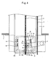
- Figure 4 is a side view of the braking device part of the elevator car for explaining the motion of the braking device for an elevator at abnormal upward acceleration in accordance with the first embodiment of the present invention.
- the components of the shoe-housing mechanism 10 are arranged in the positional relations as shown in Figure 1 . That is, the first shoe 12 is placed on the locking surface 16 of the gripping metal 11, and the whole second shoe 13 is housed in the housing groove 17 so that the braking surface 13a of the second shoe comes inside the housing groove 17 more than the braking surface 12a of the first shoe. Also, the pin 6 is arranged in a position at the upper end of the long hole 12c of the first shoe 12; as for the lever 5, the lengthwise direction thereof becomes horizontal, and the long hole 5c formed on the lever 5 is also arranged horizontally.
- the governor rope 4, which is connected to the lever 5, moves up and down the hoistway along with the car 1.
- the governor (not shown), which detects overspeed of the car 1, is activated and grips the governor rope 4.
- the lever 5, which had until then been descending together with the car 1 is rotated by the governor rope 4, and the long hole 5c on the left side of the lever 5 is pulled up.
- the rear surface 12b of the first shoe 12, which is engaged to the lever 5 via the pin 6 is moved upward along the shoe-pressing surface 15 of the gripping metal 11 by means of the roller 20, and is pushed between the gripping metal 11 and the guiderail 3.
- the braking surface 12a of the first shoe is pressed to the guiderail 3, and also the gripping metal 11 is moved in the direction to which it is pushed back by the guiderail 3 as a reaction. That is, referring to Figure 3 , the car frame 2, to which is fixed the gripping metal 11, and also the whole car 1 are moved to the right. According to this, the braking surface 14a of the receiving side shoe 14 at the opposite side of the first shoe 12 is pressed against the guiderail 3, and the pressing forces of the shoes of both sides stops the car 1.
- the deceleration speed of the elevator car 1 is adjusted by adjustment of the pressing force of the receiving side shoe 14 to the guiderail 3 by adjustment of the setting of the spring force of the spring 19 provided on the rear surface 14b of the receiving side shoe 14.
- the above-mentioned is the motion of the braking device in the case where the elevator car 1 accelerates abnormally in the downward direction, and in this case the second shoe is not activated, so as for the motion, it is similar to that of a conventional braking device wherein only one side of the shoes are moved, however, in this first embodiment, it is different from conventional braking devices in respect that it is possible to activate the braking device at abnormal upward acceleration.
- the braking surface 14a of the receiving side shoe 14 is pressed against the guiderail 3, and the pressing forces of the shoes of both sides stops the car 1. Also, similarly to abnormal downward acceleration, the deceleration speed of the elevator car 1 is adjusted by adjustment of the pressing force of the receiving side shoe 14 to the guiderail 3 by adjustment of setting of the spring force of the spring 19 provided on the rear surface 14b of the receiving side shoe 14.
- the movable side shoes that are used for braking in the upward and downward directions are different, it is possible to set the deceleration speed of the car 1 of the upward and downward directions separately by making a difference in the material, surface area, etc. of the braking surfaces of each of the shoes. Furthermore, by passing the pin 6 through the long hole 12c of the first shoe 12 and the long hole 5c of the lever 5, and also by fixing it to the second shoe 13, it is possible to drive two shoes (shoe 12 and shoe 13) with just one lever.
- the structure wherein the shoes of only one side are activated as in conventional braking devices is fundamentally taken over, and by dividing the shoe of the movable side into two shoes which correspond respectively to the upward and downward directions, it is possible to obtain a braking device which is activated not only at abnormal downward acceleration as before, but also at abnormal upward acceleration, without increasing much parts of equipment nor making the structure complex. It is also possible to improve productivity.
- Figure 5 is a drawing showing the configuration of movable side shoes of a braking device for an elevator in accordance with the second embodiment of the present invention.
- Figure 5(A) is a drawing showing the positional relation between the shoes during normal travel of the car, and at a state in which the braking device is activated at abnormal downward acceleration.
- the left drawing is an elevation of the shoes seen from the braking surface side, and the right drawing is a side view of the shoes.
- Figure 5(B) is a side view showing the positional relation between the shoes at abnormal upward acceleration.
- a roller 21 is provided between the bottom surface 18 of the housing groove 17 formed on the first shoe 12 and the rear surface 13b of the second shoe 13.
- the braking device in the present invention can be activated not only at abnormal downward acceleration of the elevator car, but also at abnormal upward acceleration. According to this, for example, in a case where the elevator car accelerates abnormally upward due to malfunction of elevator equipment or the like in the state where the counterweight is heavier than the elevator car because the number of persons riding is small, it is possible to stop the elevator car without failure, so it is useful as an elevator with improved safety.
- the braking device for an elevator in accordance with the present invention can be activated at both upward and downward abnormal acceleration without increasing the number of parts of equipment nor making the structure complex, it is useful as an elevator with improved productivity.
Landscapes
- Engineering & Computer Science (AREA)
- Mechanical Engineering (AREA)
- Maintenance And Inspection Apparatuses For Elevators (AREA)
Abstract
Claims (5)
- Dispositif de freinage pour un ascenseur comprenant :un mécanisme de logement de mâchoire (10), fixé à une cabine d'ascenseur (1) faisant face à un rail de guidage de cabine d'ascenseur (3), ayant une surface de pression de mâchoire (15) dont la partie supérieure se rétrécit vers ledit rail de guidage (3) ;une première mâchoire (12), logée dans le mécanisme de logement de mâchoire (10), ayant une surface de freinage (12a) qui fait face audit rail de guidage (3), ayant une surface arrière (12b) qui fait face à ladite surface de pression de mâchoire (15), et ayant une rainure de logement (17) qui est formée sur ladite surface de freinage (12a) et qui a une surface de fond (18) dont la partie inférieure se rétrécit vers ledit rail de guidage (3) ;une seconde mâchoire (13), logée dans ladite rainure de logement (17) de ladite première mâchoire (12), ayant une surface de freinage (13a) qui fait face audit rail de guidage (3) et une surface arrière (13b) qui fait face à ladite surface de fond (18) de ladite rainure de logement (17) ;dans lequel les deux de ladite première mâchoire (12) et de ladite seconde mâchoire (13) sont respectivement activées pour freiner en entraînant ladite première mâchoire (12) vers le haut dans le cas où ladite cabine d'ascenseur (1) accélère anormalement vers le bas, et en entraînant ladite seconde mâchoire (13) vers le bas dans le cas où ladite cabine d'ascenseur (1) accélère anormalement vers le haut, au moyen d'un levier (5) qui opère simultanément avec un câble de limiteur de vitesse (4).
- Dispositif de freinage pour un ascenseur selon la revendication 1, comprenant un goujon (6) que l'on passe à travers un trou long (12c) formé sur une des surfaces latérales de ladite rainure de logement (17) de ladite première mâchoire (12) le long de la direction d'inclinaison de la surface de fond (18) de ladite rainure de logement (17) et un trou long (5c) formé sur une des extrémités dudit levier (5), également fixé à une des surfaces latérales de ladite seconde mâchoire (13), dans lequel ladite première mâchoire (12) et ladite seconde mâchoire (13) sont entraînées par l'intermédiaire dudit goujon (6).
- Dispositif de freinage pour un ascenseur selon la revendication 2, dans lequel ledit levier (5) est formé en une forme longue ; ledit trou long (5c) sur une des extrémités dudit levier (5) est formé le long de la direction de longueur dudit levier (5) ; ledit levier (5) est mobile en rotation avec l'autre extrémité dudit levier (5) en tant que pivot ; et ledit câble de limiteur de vitesse (4) est attaché plus près dudit trou long (5c) que dudit pivot.
- Dispositif de freinage pour un ascenseur selon la revendication 2 ou 3, dans lequel ledit mécanisme de logement de mâchoire (10) comprend une surface de verrouillage (16) pour commander le mouvement vers le bas de la première mâchoire (12), et ladite première mâchoire (12) est placée sur ladite surface de verrouillage (16) pendant un déplacement normal de ladite cabine d'ascenseur (1).
- Dispositif de freinage pour un ascenseur selon l'une quelconque des revendications 1 à 4, dans lequel un rouleau (21) est prévu entre ladite surface de fond (18) de rainure de logement (17) de ladite première mâchoire (12) et ladite surface arrière (13b) de ladite seconde mâchoire (13).
Applications Claiming Priority (1)
| Application Number | Priority Date | Filing Date | Title |
|---|---|---|---|
| PCT/JP2002/012707 WO2004050525A1 (fr) | 2002-12-04 | 2002-12-04 | Systeme de freinage pour ascenseur |
Publications (3)
| Publication Number | Publication Date |
|---|---|
| EP1568643A1 EP1568643A1 (fr) | 2005-08-31 |
| EP1568643A4 EP1568643A4 (fr) | 2010-09-01 |
| EP1568643B1 true EP1568643B1 (fr) | 2011-09-14 |
Family
ID=32449000
Family Applications (1)
| Application Number | Title | Priority Date | Filing Date |
|---|---|---|---|
| EP02788718A Expired - Lifetime EP1568643B1 (fr) | 2002-12-04 | 2002-12-04 | Systeme de freinage pour ascenseur |
Country Status (5)
| Country | Link |
|---|---|
| EP (1) | EP1568643B1 (fr) |
| JP (1) | JP4170295B2 (fr) |
| KR (1) | KR100611596B1 (fr) |
| CN (1) | CN100337896C (fr) |
| WO (1) | WO2004050525A1 (fr) |
Families Citing this family (22)
| Publication number | Priority date | Publication date | Assignee | Title |
|---|---|---|---|---|
| KR100763830B1 (ko) * | 2006-05-19 | 2007-10-23 | 윤재한 | 엘리베이터용 로프제동장치 |
| PT1942071E (pt) * | 2007-01-08 | 2011-02-17 | Thyssenkrupp Elevator Mfg Spain S L | Meios de flutuação para o aperto adequado de um dispositivo de segurança |
| FI125327B (fi) * | 2009-01-12 | 2015-08-31 | Kone Corp | Hissikorin liikkeen estävällä lukituslaitteella varustettu hissi ja hissikorin liikkeen estävä lukituslaite |
| CN101575062B (zh) * | 2009-05-18 | 2011-05-11 | 杭州沪宁电梯配件有限公司 | 非对称渐进式安全钳 |
| EP2495205B1 (fr) | 2009-10-28 | 2015-12-02 | Mitsubishi Electric Corporation | Dispositif d'arrêt d'urgence pour ascenseurs |
| JP2011126679A (ja) * | 2009-12-18 | 2011-06-30 | Hitachi Ltd | エレベータの制動装置 |
| CN102465982B (zh) * | 2010-10-29 | 2013-11-20 | 武汉市江汉石油机械有限公司 | 重负荷自由落体刹车装置 |
| KR20130122663A (ko) * | 2011-04-01 | 2013-11-07 | 미쓰비시덴키 가부시키가이샤 | 엘리베이터 장치 |
| ES2565828T3 (es) * | 2011-04-19 | 2016-04-07 | Otis Elevator Company | Freno de elevador que tiene una característica de liberación de freno |
| JP5863967B2 (ja) * | 2011-07-29 | 2016-02-17 | オーチス エレベータ カンパニーOtis Elevator Company | 調節可能なセーフティブレーキ |
| CN104125923B (zh) * | 2012-02-17 | 2019-10-18 | 因温特奥股份公司 | 具有可变摩擦度的制动系统 |
| JP5926603B2 (ja) * | 2012-04-25 | 2016-05-25 | 株式会社日立製作所 | エレベータ |
| JP2014065591A (ja) * | 2012-09-27 | 2014-04-17 | Hitachi Ltd | 非常止め装置を備えたエレベーター |
| AU2013351430B2 (en) * | 2012-11-27 | 2016-12-22 | Inventio Ag | Catching device for a traveling body of an elevator system |
| CN103274274A (zh) * | 2013-04-09 | 2013-09-04 | 康力电梯股份有限公司 | 一种安全钳 |
| CN106956989B (zh) * | 2015-09-12 | 2020-03-27 | 奥的斯电梯公司 | 电梯超速调节器 |
| CN105905741B (zh) * | 2016-06-28 | 2017-12-19 | 爱默生电梯有限公司 | 一种电梯安全钳 |
| CN109279474B (zh) | 2017-07-21 | 2021-05-07 | 奥的斯电梯公司 | 安全装置,电梯安全系统及电梯系统 |
| CN110342368B (zh) * | 2018-04-04 | 2024-05-31 | 迈格钠磁动力股份有限公司 | 电梯永磁缓速安全保护装置和电梯 |
| EP3604196B1 (fr) | 2018-08-03 | 2023-04-26 | Otis Elevator Company | Ensemble actionneur de sécurité électronique pour système d'ascenseur |
| CN115465748A (zh) * | 2021-06-10 | 2022-12-13 | 奥的斯电梯公司 | 用于电梯系统的安全装置和电梯系统 |
| CN115504349A (zh) * | 2022-09-23 | 2022-12-23 | 台州市特种设备检验检测研究院 | 一种用于防止电梯意外移动的夹持式滑块制动装置 |
Family Cites Families (5)
| Publication number | Priority date | Publication date | Assignee | Title |
|---|---|---|---|---|
| JPS5943342Y2 (ja) * | 1978-02-15 | 1984-12-21 | 三菱電機株式会社 | エレベ−タの非常止め装置 |
| FI85129C (fi) * | 1989-12-14 | 1992-03-10 | Kone Oy | Faongapparat. |
| DE29614516U1 (de) * | 1996-08-21 | 1998-01-02 | C. Haushahn Gmbh & Co, 70469 Stuttgart | Fangvorrichtung |
| JP2001192184A (ja) * | 2000-01-11 | 2001-07-17 | Toshiba Corp | エレベータ非常止め装置 |
| JP2002154761A (ja) * | 2000-11-14 | 2002-05-28 | Otis Elevator Co | 非鉄製ガイドレール用安全装置 |
-
2002
- 2002-12-04 EP EP02788718A patent/EP1568643B1/fr not_active Expired - Lifetime
- 2002-12-04 JP JP2004556805A patent/JP4170295B2/ja not_active Expired - Fee Related
- 2002-12-04 WO PCT/JP2002/012707 patent/WO2004050525A1/fr not_active Ceased
- 2002-12-04 CN CNB028232046A patent/CN100337896C/zh not_active Expired - Fee Related
- 2002-12-04 KR KR1020047007580A patent/KR100611596B1/ko not_active Expired - Fee Related
Also Published As
| Publication number | Publication date |
|---|---|
| CN100337896C (zh) | 2007-09-19 |
| JPWO2004050525A1 (ja) | 2006-03-30 |
| EP1568643A4 (fr) | 2010-09-01 |
| WO2004050525A1 (fr) | 2004-06-17 |
| KR100611596B1 (ko) | 2006-08-10 |
| JP4170295B2 (ja) | 2008-10-22 |
| CN1589226A (zh) | 2005-03-02 |
| KR20040082375A (ko) | 2004-09-24 |
| EP1568643A1 (fr) | 2005-08-31 |
Similar Documents
| Publication | Publication Date | Title |
|---|---|---|
| EP1568643B1 (fr) | Systeme de freinage pour ascenseur | |
| EP3677534B1 (fr) | Actioneur d'un dispositif de sécurité d'ascenseur | |
| KR101537846B1 (ko) | 엘리베이터용 비상멈춤장치 | |
| KR101033378B1 (ko) | 엘리베이터의 안전장치 | |
| US8550217B2 (en) | Elevator | |
| CN111712455B (zh) | 紧急停止装置及电梯 | |
| CN108290713B (zh) | 电梯装置 | |
| US8006806B2 (en) | Emergency brake of elevator | |
| EP3670416B1 (fr) | Frein de sécurité pour un contrepoids activé par une couche de traction | |
| KR20160092478A (ko) | 에스컬레이터 | |
| EP3328772B1 (fr) | Bloc de sécurité pour ascenseur | |
| KR100889280B1 (ko) | 엘리베이터의 로프 제동장치 | |
| CN109534125B (zh) | 电梯安全装置组件 | |
| KR200386599Y1 (ko) | 엘리베이터용 양방향 비상정지장치 | |
| EP4678579A1 (fr) | Agencement de frein de sécurité d'ascenseur | |
| EP4574731A1 (fr) | Dispositif de sécurité pour ascenseur | |
| JP7854962B2 (ja) | エレベーターのかごドア装置 | |
| EP3569546A1 (fr) | Engrenage de sécurité d'ascenseur | |
| EP3569548A1 (fr) | Ensemble d'engrenage de sécurité d'ascenseur | |
| JPS5926875A (ja) | 斜行エレベ−タの非常止め装置 |
Legal Events
| Date | Code | Title | Description |
|---|---|---|---|
| PUAI | Public reference made under article 153(3) epc to a published international application that has entered the european phase |
Free format text: ORIGINAL CODE: 0009012 |
|
| 17P | Request for examination filed |
Effective date: 20040615 |
|
| AK | Designated contracting states |
Kind code of ref document: A1 Designated state(s): AT BE BG CH CY CZ DE DK EE ES FI FR GB GR IE IT LI LU MC NL PT SE SK TR |
|
| RBV | Designated contracting states (corrected) |
Designated state(s): DE |
|
| RAP1 | Party data changed (applicant data changed or rights of an application transferred) |
Owner name: MITSUBISHI DENKI KABUSHIKI KAISHA |
|
| A4 | Supplementary search report drawn up and despatched |
Effective date: 20100802 |
|
| GRAP | Despatch of communication of intention to grant a patent |
Free format text: ORIGINAL CODE: EPIDOSNIGR1 |
|
| RIC1 | Information provided on ipc code assigned before grant |
Ipc: B66B 5/04 20060101ALI20110215BHEP Ipc: B66B 5/22 20060101AFI20110215BHEP |
|
| GRAS | Grant fee paid |
Free format text: ORIGINAL CODE: EPIDOSNIGR3 |
|
| GRAA | (expected) grant |
Free format text: ORIGINAL CODE: 0009210 |
|
| AK | Designated contracting states |
Kind code of ref document: B1 Designated state(s): DE |
|
| REG | Reference to a national code |
Ref country code: DE Ref legal event code: R096 Ref document number: 60241054 Country of ref document: DE Effective date: 20111110 |
|
| PLBE | No opposition filed within time limit |
Free format text: ORIGINAL CODE: 0009261 |
|
| STAA | Information on the status of an ep patent application or granted ep patent |
Free format text: STATUS: NO OPPOSITION FILED WITHIN TIME LIMIT |
|
| 26N | No opposition filed |
Effective date: 20120615 |
|
| REG | Reference to a national code |
Ref country code: DE Ref legal event code: R097 Ref document number: 60241054 Country of ref document: DE Effective date: 20120615 |
|
| REG | Reference to a national code |
Ref country code: DE Ref legal event code: R084 Ref document number: 60241054 Country of ref document: DE Effective date: 20140326 |
|
| PGFP | Annual fee paid to national office [announced via postgrant information from national office to epo] |
Ref country code: DE Payment date: 20171129 Year of fee payment: 16 |
|
| REG | Reference to a national code |
Ref country code: DE Ref legal event code: R119 Ref document number: 60241054 Country of ref document: DE |
|
| PG25 | Lapsed in a contracting state [announced via postgrant information from national office to epo] |
Ref country code: DE Free format text: LAPSE BECAUSE OF NON-PAYMENT OF DUE FEES Effective date: 20190702 |