EP1568914B1 - Amortisseur de vibrations torsionelles et sa méthode de production - Google Patents
Amortisseur de vibrations torsionelles et sa méthode de production Download PDFInfo
- Publication number
- EP1568914B1 EP1568914B1 EP05011837A EP05011837A EP1568914B1 EP 1568914 B1 EP1568914 B1 EP 1568914B1 EP 05011837 A EP05011837 A EP 05011837A EP 05011837 A EP05011837 A EP 05011837A EP 1568914 B1 EP1568914 B1 EP 1568914B1
- Authority
- EP
- European Patent Office
- Prior art keywords
- torsional vibration
- vibration damper
- wedge
- friction
- double wedge
- Prior art date
- Legal status (The legal status is an assumption and is not a legal conclusion. Google has not performed a legal analysis and makes no representation as to the accuracy of the status listed.)
- Expired - Lifetime
Links
Images




Classifications
-
- F—MECHANICAL ENGINEERING; LIGHTING; HEATING; WEAPONS; BLASTING
- F16—ENGINEERING ELEMENTS AND UNITS; GENERAL MEASURES FOR PRODUCING AND MAINTAINING EFFECTIVE FUNCTIONING OF MACHINES OR INSTALLATIONS; THERMAL INSULATION IN GENERAL
- F16F—SPRINGS; SHOCK-ABSORBERS; MEANS FOR DAMPING VIBRATION
- F16F15/00—Suppression of vibrations in systems; Means or arrangements for avoiding or reducing out-of-balance forces, e.g. due to motion
- F16F15/10—Suppression of vibrations in rotating systems by making use of members moving with the system
- F16F15/12—Suppression of vibrations in rotating systems by making use of members moving with the system using elastic members or friction-damping members, e.g. between a rotating shaft and a gyratory mass mounted thereon
- F16F15/131—Suppression of vibrations in rotating systems by making use of members moving with the system using elastic members or friction-damping members, e.g. between a rotating shaft and a gyratory mass mounted thereon the rotating system comprising two or more gyratory masses
- F16F15/133—Suppression of vibrations in rotating systems by making use of members moving with the system using elastic members or friction-damping members, e.g. between a rotating shaft and a gyratory mass mounted thereon the rotating system comprising two or more gyratory masses using springs as elastic members, e.g. metallic springs
- F16F15/134—Wound springs
-
- F—MECHANICAL ENGINEERING; LIGHTING; HEATING; WEAPONS; BLASTING
- F16—ENGINEERING ELEMENTS AND UNITS; GENERAL MEASURES FOR PRODUCING AND MAINTAINING EFFECTIVE FUNCTIONING OF MACHINES OR INSTALLATIONS; THERMAL INSULATION IN GENERAL
- F16F—SPRINGS; SHOCK-ABSORBERS; MEANS FOR DAMPING VIBRATION
- F16F15/00—Suppression of vibrations in systems; Means or arrangements for avoiding or reducing out-of-balance forces, e.g. due to motion
- F16F15/10—Suppression of vibrations in rotating systems by making use of members moving with the system
- F16F15/12—Suppression of vibrations in rotating systems by making use of members moving with the system using elastic members or friction-damping members, e.g. between a rotating shaft and a gyratory mass mounted thereon
- F16F15/131—Suppression of vibrations in rotating systems by making use of members moving with the system using elastic members or friction-damping members, e.g. between a rotating shaft and a gyratory mass mounted thereon the rotating system comprising two or more gyratory masses
- F16F15/133—Suppression of vibrations in rotating systems by making use of members moving with the system using elastic members or friction-damping members, e.g. between a rotating shaft and a gyratory mass mounted thereon the rotating system comprising two or more gyratory masses using springs as elastic members, e.g. metallic springs
- F16F15/134—Wound springs
- F16F15/1343—Wound springs characterised by the spring mounting
- F16F15/13438—End-caps for springs
-
- F—MECHANICAL ENGINEERING; LIGHTING; HEATING; WEAPONS; BLASTING
- F16—ENGINEERING ELEMENTS AND UNITS; GENERAL MEASURES FOR PRODUCING AND MAINTAINING EFFECTIVE FUNCTIONING OF MACHINES OR INSTALLATIONS; THERMAL INSULATION IN GENERAL
- F16F—SPRINGS; SHOCK-ABSORBERS; MEANS FOR DAMPING VIBRATION
- F16F15/00—Suppression of vibrations in systems; Means or arrangements for avoiding or reducing out-of-balance forces, e.g. due to motion
- F16F15/10—Suppression of vibrations in rotating systems by making use of members moving with the system
- F16F15/12—Suppression of vibrations in rotating systems by making use of members moving with the system using elastic members or friction-damping members, e.g. between a rotating shaft and a gyratory mass mounted thereon
- F16F15/131—Suppression of vibrations in rotating systems by making use of members moving with the system using elastic members or friction-damping members, e.g. between a rotating shaft and a gyratory mass mounted thereon the rotating system comprising two or more gyratory masses
- F16F15/139—Suppression of vibrations in rotating systems by making use of members moving with the system using elastic members or friction-damping members, e.g. between a rotating shaft and a gyratory mass mounted thereon the rotating system comprising two or more gyratory masses characterised by friction-damping means
Definitions
- the invention relates to a torsional vibration damper and a method for damping torsional vibrations.
- Such torsional vibration dampers are known in a variety of concrete embodiments.
- An important focus in the structural design of such torsional vibration damper is that the damping properties of such a torsional vibration damper should be influenced in a suitable manner. For example, there is the requirement that at low rotational amplitudes between the masses little attenuation should occur, while at high amplitudes high attenuation is desired. At the same time high damping should occur at high rotational speeds, while at low rotational speeds only little damping should occur.
- Torsionsschwingungsdämpfer with two mutually rotatably mounted masses and an inter-mass friction device comprising a mitschleppenden wedge, which is arranged in a at least partially filled with a viscous additive chamber are for example from DE 198 17 906 A1 , which are the closest prior art EP 0 863 330 A1 , of the US 5,072,818 or the US 5,569,088 known.
- the arrangements disclosed there have a plurality of assemblies, which are very must interact in a complex manner to allow for suitable damping.
- the invention proposes on the one hand a method for damping torsional vibrations by means of a torsional vibration damper with two mutually rotatably mounted masses and with an effective between the mass friction device comprising a mitschleppenden double wedge, which is arranged in a at least partially filled with a viscous additive chamber which method is characterized in that is tilted with respect to an axis of the torsional vibration damper in a relative movement of the two masses of the double wedge.
- the invention proposes as a solution a torsional vibration damper with two mutually rotatably mounted masses and with an effective between the mass friction device comprising a mitschleppenden wedge, which is arranged in a at least partially filled with a viscous additive, walls having chamber, wherein the double wedge is arranged such that it performs a tilting movement with respect to an axis of the torsional vibration damper in a relative movement of the two masses.
- the term "entrained” refers to an assembly which is arranged between the two masses so that they can follow this movement in the context of a possible relative movement of the two masses to each other, if the friction is neglected. In other words, neglecting the friction does not interfere with a moving assembly the relative movement between the two rotatably mounted masses of the torsional vibration damper.
- the term "wedge” describes an assembly having two opposing surface areas whose pitch varies along the surface area.
- such a wedge may be provided between two friction surfaces whose spacing varies along the circumference of the torsional vibration damper.
- the distance of the friction surfaces changes rectified as the distance of the corresponding wedge surfaces, but the degree of change does not have to be chosen identical, but can be adapted to the respective requirements.
- the wedge may be arranged between two friction surfaces having substantially axial surfaces.
- Such an arrangement requires a substantially radial flow of wedging occurring Forces.
- Such radially directed forces can be compensated for in a particularly simple manner with essentially rotationally symmetrical torsional vibration dampers.
- Complex surface calculations and surface treatments can be dispensed with if at least one of the surfaces, be it a wedge surface or a friction surface, is designed to be partly cylindrical, at least in the region of the interaction between the wedge and the friction surface.
- the term partially cylindrical describes a surface area whose design corresponds to a shell segment of a cylinder.
- At least one of the cylindrically shaped surfaces may have a cylinder axis which corresponds to the main axis of rotation of the torsional vibration damper.
- At least one of the cylindrically shaped surfaces can be arranged offset in parallel with respect to the axis of rotation of the torsional vibration damper. In this way can be provided in a structurally relatively simple manner distance variable surfaces, especially if they are assigned to another partially cylindrical surface with a different radius and / or with another axis position.
- the wedge may have at least one partially cylindrical wedge surface.
- the radius can correspond to a corresponding surface area of a corresponding friction surface on which the wedge rests.
- the identical radius then implies that the wedge can interact with the friction surface over a relatively large surface area, whereby advantageous frictional properties can be achieved.
- the friction device according to the invention is particularly suitable as vinreib dressed a torsional vibration damper, in which the two masses are operatively connected to each other by means of at least one spring-friction device.
- the torsional vibration damper thus comprises on the one hand a spring-friction device, which on the one hand has an elastic restoring moment in the direction of a rest position of the torsional vibration damper and on the other hand due to the friction damping properties, and a friction device according to the invention with a mitschleppenden double wedge as a separate assembly.
- the friction device is rigid except for the inherent elasticity of the wedge and the corresponding friction surfaces which interact with the wedge.
- the friction device in particular should not include any elastic auxiliary device, such as coil springs or spring clips.
- the wedge according to the invention is designed as a double wedge. This makes it possible to take into account structurally relatively simple manner the fact that torsional vibrations can occur in different directions of rotation.
- a double wedge causes the double wedge to be excited due to a relative movement of the two masses of the torsional vibration damper to a tilting movement, which advantageously influences a wedge effect or a friction effect.
- the double wedge substantially has a kidney shape.
- a kidney shape is relatively compact and thus can absorb relatively large forces.
- such a form can be adjusted in a structurally simple manner that allows to tow away.
- the double wedge may have at least two part-cylindrical, spaced-apart wedge surfaces of substantially identical radius. Such surface areas can readily abut against a continuous cylindrical friction surface of the rest of the torsional vibration damper, whereby the overall arrangement can be constructed in a structurally relatively simple manner.
- the two wedge surfaces may be formed around the same axis, so that the double wedge can rest with both part-cylindrical wedge surfaces on a continuous cylindrical friction surface.
- the two wedge surfaces may also be formed around mutually parallel axes. This ensures that the double wedge with a tilting of the same with the largest possible surface on the friction surface can rest.
- a recess can be provided between these two wedge surfaces, whereby on the one hand tilting and, on the other hand, a discontinuous transition between two surface regions resting against a friction surface can be avoided.
- the double wedge is arranged such that it performs a tilting movement with respect to an axis of the torsional vibration damper in a relative movement of the two masses.
- suitable surface areas of the double wedge can then be brought into frictional contact with corresponding friction surfaces.
- the wedge can at least partially engage with it Be arranged a viscous admixture filled chamber.
- the viscous additive provides the necessary initial power.
- such an initial force reliably ensures that the wedge is not entrained in an undefined manner before its wedging and self-reinforcing action commences.
- the viscous additive allows a speed-dependent friction, which is already effective even at very low vibration amplitudes. Moreover, this arrangement reliably prevents an unnecessary free play which unpredictably affects the attenuation.
- the wedge may have at least one projection.
- the resistance to shear forces of the viscous additive can be increased, whereby the overall effect of the viscous additive is increased accordingly.
- This increase in activity follows directly from the larger attack surface that generates such a projection.
- the projection in a wedge enclosing space or in a wedge enclosing chamber creates an increased volume of space for receiving viscous additive.
- suitable fats can be used.
- the at least one projection is provided on one side of the wedge, which is not used as a wedge surface.
- the wedge surface which can be effective, is not reduced, while the beneficial effects of such a projection can be utilized.
- the projection may have in the axial direction, whereby on the one hand circumferentially facing surface areas, which interact particularly pronounced with the viscous additive arise, and on the other hand, an additional friction on walls of a chamber surrounding the wedge, can be ensured, which has a wedge effect in the radial Direction takes place, not impaired.
- a relatively simple assembly or production of the torsional vibration damper can be achieved in that the chamber is at least partially covered by a metal sheet on at least one radial side.
- the term describes a radial side of the chamber which can be covered or closed by a radially directed surface.
- the term axial surface describes a surface having a surface component parallel to the axis of the torsional vibration damper.
- the chamber is at least partially covered by a metal sheet on at least one radial side.
- a metal sheet on at least one radial side.
- profiles such as, for example, a design of non-rotationally symmetrical cylinder shapes or the like, can be made easily on such metal sheets.
- the sheet may have a flange for stability reasons or to allow a connection with other assemblies.
- the flange can form a substantially radial frictional engagement between the sheet and the mass.
- the sheet can first be positioned on the corresponding mass and then be crimped so that between the sheet and the mass such a frictional engagement arises. It is also conceivable that the sheet is first vorgebördelt and then positioned accordingly before a final curl leads to such a frictional engagement.
- the torsional vibration damper has at least two chambers, which are at least partially covered by a metal sheet on at least one of its sides, it is advantageous to manufacture the two sheet metal covers from the same material and to design the chambers and the sheet metal covers in such a way that the one plate is raclially inside of the other sheet can be arranged without the two sheets overlap each other. This is especially true for chambers that by the axis of the torsional vibration damper revolving plates are covered.
- the term "in the stretched state” means that any bends, formations or the like are intended to be removed from the sheets.
- both sheet metal covers are made of the same blank, or that the one sheet metal cover is made of a blank from which a sheet metal cover, which corresponds to the second sheet metal cover was made. In this way can be used to produce the sheet metal covers required material savings, since less waste.
- the sheets are formed from a single blank, they can then - if appropriate, in a single step - be subjected to a shaping.
- such a metal sheet which should be firmly connected to one of the masses, be fixed between two of these assemblies. This can be done for example by a screw that fixes the two modules together. As a result, no extra work step needs to be provided for fixing.
- the assembly ease gained here justifies a higher outlay, which is needed for the increase in accuracy, which is due to an increase in manufacturing tolerances.
- the sheet can then form at least one side of the bearing shell.
- Such a sheet may also be secured in a groove.
- a groove is formed directed radially inward.
- a sealant can be introduced between the sheet and the corresponding, this sheet holding assembly. This may be, for example, silicone rubber or other rubber-elastic sealant. Likewise, a surface seal or a paper seal can be provided.
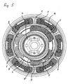
- Each of the torsional vibration damper shown in the drawing has a primary mass 1 and a secondary mass 2, which are operatively connected to each other via a spring-friction device 3.
- the secondary mass 2 is rotatably mounted with respect to the primary mass 1 in a bearing shell, which is formed by a second assembly 4 of the primary mass 1.
- Such torsional vibration dampers are known per se.
- the chamber 6 has a radially outer cylindrical friction surface against which the wedges 5 abut.
- these wedges can contribute to negligible friction, but in particular in the range of the allowed by the spring means 3 amplitude entrained.
- friction device of each of the torsional vibration damper on friction surfaces 8 which are partially cylindrical, offset in parallel with respect to the axis of rotation of the torsional vibration damper.
- these friction surfaces are provided in the embodiment shown in Figures 1 and 2 to drivers 8 ', which engage in corresponding recesses of the wedges 5.
- these friction surfaces 8 are configured on a profiled sheet-metal disk 8 ", which is arranged between the two assemblies 1 and 4 of the primary mass.
- each of the wedges 5 is formed as a double wedge and has four partial cylindrical wedge surfaces.
- the radially outer wedge surfaces have the same radius as the radially outer friction surface 7, wherein, however, the cylinder axis is offset parallel to the axis of the torsional vibration damper.
- the friction device on no resilient assemblies, so that it is rigid except for the inherent elasticity of the wedges 5 and the friction surfaces 7 and 8 forming assemblies.
- the double wedges 5 essentially have a kidney shape, with tilting of the double wedges 5 occurring during a relative movement of primary mass 1, 4 and secondary mass due to the offset cylinder axes of the outer wedge surfaces. Between the outer wedge surfaces of each double wedge 5 transition areas are provided. These are designed in the embodiment shown in Figures 1 and 2 as a rectangular surface, while in the embodiments shown in Figures 3 to 6, a cylindrical surface is selected with a smaller radius than the radius of the friction surface 7. This connection surface is arranged in your radius and in your axis such that at the transition between connecting surface and wedge surface in each case the same angle of inclination or the same tangent occurs.
- the chamber 6 is partially filled with a viscous additive.
- each of the wedges 5 projections 9 which point in the axial direction. This produces surface areas which counteract the shear forces of the viscous additive, so that the double wedge according to the invention becomes effective without free play.
- the projections 9 are designed such that they extend to radial walls of the chamber 6, so that even at these points friction is given. Between the projections 9 gaps are created, which allow an increased capacity for the viscous additive.
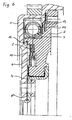
- the chamber 6 of the exemplary embodiments illustrated in FIGS. 3 to 6 is in axial directions Sheets 10 and 11 bounded. These sheets are provided with a flange 12, wherein this flange forms a radial frictional engagement with the secondary mass 2 and fixed in this way the sheets 10 and 11 on the secondary mass.
- the two metal sheets 10 and 11 are first pre-crimped in a pre-assembly. These are then positioned on the secondary mass in the desired manner. Only then is the flange 12 completed and generated in this way the frictional engagement between the sheets 10 and 11 with the secondary mass 2.
- the sheet 10 is attached. Again, only after the positioning of the sheet 10 of the frictional engagement between secondary mass 2 and sheet 10 is generated via the flange 12.
- the sheet 10 and a Abdichtblech 13 for the spring-friction device 3 made of the same material.
- the sheets 10 and 13 or 8" and 14 are made from the same blank, so that for the sheets 8 "and 10th In this respect, only the sheet 11 is additional for the friction device according to the invention in the embodiment shown in Figures 3 to 5 Chamber limitation in terms of material costs of importance.
- the secondary mass is formed in a suitable manner, so that for the chamber formation 6 no additional material is needed.
- FIG. 7 shows the arrangement before pressing so immediately after the sheet (2 ') is brought into its mounting position.
- Figure 8 shows the arrangement after the pressing of the sheet (10 ') in the groove (2'). Since such pressing-in takes place only at certain positions distributed around the circumference, FIG. 7 shows the arrangement at the circumferential positions at which pressing-in is not present.
- a sealant such as silicone rubber introduced.
Landscapes
- Engineering & Computer Science (AREA)
- General Engineering & Computer Science (AREA)
- Physics & Mathematics (AREA)
- Acoustics & Sound (AREA)
- Aviation & Aerospace Engineering (AREA)
- Mechanical Engineering (AREA)
- Mechanical Operated Clutches (AREA)
Claims (10)
- Procédé d'amortissement d'oscillations de torsion au moyen d'un amortisseur d'oscillations de torsion comportant deux masses rotatives tournant en sens opposé (1, 4 ; 2) ainsi qu'un dispositif de friction disposé entre les masses (1, 4 ; 2) comprenant au moins un double coin d'entraînement (5) agencé dans une chambre (6) remplie au moins partiellement d'un mélange visqueux, caractérisé en ce que le double coin est basculé par rapport à un axe de l'amortisseur d'oscillations de torsion lors d'un déplacement relatif des deux masses (1, 4 ; 2).
- Procédé selon la revendication 1, caractérisé en ce que le double coin comporte deux surfaces de friction (7), entre lesquelles est disposée une surface de jonction constituée de telle manière que le même angle d'inclinaison ou la même tangente est toujours présent à la transition entre la surface de jonction et les surfaces de friction.
- Amortisseur d'oscillations de torsion comportant deux masses rotatives tournant en sens opposé (1, 4 ; 2) ainsi qu'un dispositif de friction disposé entre les masses (1, 4 ; 2) comportant au moins un double coin d'entraînement (5) agencé dans une chambre (6) comportant des parois et remplie au moins partiellement d'un mélange visqueux, caractérisé en ce que le double coin (5) est disposé de telle façon qu'il effectue un mouvement de basculement par rapport à un axe de l'amortisseur d'oscillations de torsion lors d'un déplacement relatif des deux masses (1, 4 ; 2).
- Amortisseur d'oscillations de torsion selon la revendication 3, caractérisé en ce que le coin (5) est disposé entre deux surfaces de friction (7, 8) essentiellement axiales de forme au moins partiellement cylindrique dans la zone d'interaction entre le coin (5) et les surfaces de friction (7, 8) et décalées parallèlement par rapport à un axe de rotation de l'amortisseur d'oscillations de torsion.
- Amortisseur d'oscillations de torsion selon la revendication 3 ou 4, caractérisé en ce que le double coin (5) comporte au moins une projection (9) dirigée depuis le double coin (5) en direction d'une paroi de la chambre (6) et dont une autre face constitue la surface de travail du coin.
- Amortisseur d'oscillations de torsion selon l'une quelconque des revendications 3 à 5, caractérisé en ce que le double coin comporte deux surfaces de friction (7) entre lesquelles est disposée une surface de jonction, constituée de telle manière que le même angle d'inclinaison ou la même tangente est toujours présent à la transition entre la surface de jonction et les surfaces de friction.
- Amortisseur d'oscillations de torsion selon l'une quelconque des revendications 5 à 6, caractérisé par une pluralité de projections.
- Amortisseur d'oscillations de torsion selon l'une quelconque des revendications 5 à 7, caractérisé en ce que la projection est disposée en direction axiale.
- Amortisseur d'oscillations de torsion selon la revendication 8, caractérisé en ce que la projection atteint une paroi radiale de la chambre (6).
- Amortisseur d'oscillations de torsion selon l'une quelconque des revendications 5 à 8, caractérisé en ce que la projection atteint une paroi de la chambre (6).
Applications Claiming Priority (5)
| Application Number | Priority Date | Filing Date | Title |
|---|---|---|---|
| DE19925487 | 1999-06-04 | ||
| DE19925487 | 1999-06-04 | ||
| DE19940793 | 1999-08-27 | ||
| DE19940793A DE19940793A1 (de) | 1999-06-04 | 1999-08-27 | Torsionsschwingungsdämpfer sowie Verfahren zur Herstellung eines Torsionsschwingungsdämpfers |
| EP20000110331 EP1058028B1 (fr) | 1999-06-04 | 2000-05-13 | Amortisseur de vibrations torsionelles et sa méthode de production |
Related Parent Applications (1)
| Application Number | Title | Priority Date | Filing Date |
|---|---|---|---|
| EP20000110331 Division EP1058028B1 (fr) | 1999-06-04 | 2000-05-13 | Amortisseur de vibrations torsionelles et sa méthode de production |
Publications (2)
| Publication Number | Publication Date |
|---|---|
| EP1568914A1 EP1568914A1 (fr) | 2005-08-31 |
| EP1568914B1 true EP1568914B1 (fr) | 2007-09-26 |
Family
ID=7910149
Family Applications (1)
| Application Number | Title | Priority Date | Filing Date |
|---|---|---|---|
| EP05011837A Expired - Lifetime EP1568914B1 (fr) | 1999-06-04 | 2000-05-13 | Amortisseur de vibrations torsionelles et sa méthode de production |
Country Status (2)
| Country | Link |
|---|---|
| EP (1) | EP1568914B1 (fr) |
| DE (2) | DE19940793A1 (fr) |
Families Citing this family (4)
| Publication number | Priority date | Publication date | Assignee | Title |
|---|---|---|---|---|
| DE102004036939A1 (de) * | 2004-04-07 | 2005-10-27 | Rohs-Voigt Patentverwertungsgesellschaft Mbh | Zweimassenschwungrad mit einer Primärmasse, einem Federsystem und einer Sekundärmasse |
| DE102013003627A1 (de) * | 2013-03-05 | 2014-09-11 | Ulrich Rohs | Torsionsschwingungsdämpfer mit zumindest einer Primärseite und einer Sekundärseite |
| FR3058770A1 (fr) * | 2016-11-14 | 2018-05-18 | Valeo Embrayages | Amortisseur de torsion et vehicule automobile |
| DE102018219406A1 (de) * | 2018-11-14 | 2020-05-14 | Zf Friedrichshafen Ag | Torsionsschwingungsdämpfer mit nasslaufender Reibeinrichtung und Kupplungsscheibe mit Torsionsschwingungsdämpfer |
Family Cites Families (5)
| Publication number | Priority date | Publication date | Assignee | Title |
|---|---|---|---|---|
| US1840655A (en) * | 1927-01-24 | 1932-01-12 | Chrysler Corp | Vibration dampener |
| DE3909234C1 (fr) * | 1989-03-21 | 1990-05-31 | J.M. Voith Gmbh, 7920 Heidenheim, De | |
| DE4335207A1 (de) * | 1993-10-15 | 1995-04-20 | Fichtel & Sachs Ag | Geteilte Schwungradvorrichtung mit Axiallagerung im Umfangbereich |
| DE19708328A1 (de) * | 1997-01-31 | 1998-08-13 | Rohs Voigt Patentverwertungsge | Mechanischer Torsionsschwingungsdämpfer |
| DE19817906A1 (de) * | 1997-10-29 | 1999-05-06 | Rohs Voigt Patentverwertungsge | Torsionsschwingungsdämpfer |
-
1999
- 1999-08-27 DE DE19940793A patent/DE19940793A1/de not_active Ceased
-
2000
- 2000-05-13 DE DE50010804T patent/DE50010804D1/de not_active Expired - Lifetime
- 2000-05-13 EP EP05011837A patent/EP1568914B1/fr not_active Expired - Lifetime
Also Published As
| Publication number | Publication date |
|---|---|
| DE19940793A1 (de) | 2000-12-07 |
| EP1568914A1 (fr) | 2005-08-31 |
| DE50010804D1 (de) | 2005-09-01 |
Similar Documents
| Publication | Publication Date | Title |
|---|---|---|
| DE19624886C2 (de) | Flüssigkeitsdämpfungsvorrichtung mit unterschiedlich großen Federsteifigkeitswerten in zwei zueinander senkrechten Richtungen | |
| DE4115382C2 (de) | Hydraulischer Dämpfer | |
| DE10358888A1 (de) | Brennkraftmaschine mit einer hydraulischen Vorrichtung zur Drehwinkelverstellung einer Nockenwelle gegenüber einer Kurbelwelle | |
| DE10332098A1 (de) | Dämpfer | |
| EP1042576A1 (fr) | Ferme-porte | |
| WO2001004507A1 (fr) | Ressort a torsion, amortisseur de vibrations torsionnelles, et dispositif comportant un ressort a torsion | |
| EP1711390B1 (fr) | Palier reglable par clavette pour mecanisme de direction de vehicule automobile | |
| DE102020207340A1 (de) | Parksperreneinrichtung für ein Fahrzeug und Verfahren zum Herstellen einer Parksperreneinrichtung für ein Fahrzeug | |
| DE19803174A1 (de) | Kolben-Zylinderaggregat mit einem Führungslager | |
| EP2218938A1 (fr) | Dispositif d'amortissement, notamment pour un degré d'oscillation de deux masses | |
| DE3616301A1 (de) | Torsionsschwingungsdaempfer | |
| DE69502777T2 (de) | Torsionsschwingungsvordämpfer, insbesondere für kraftfahrzeuge | |
| DE69513911T2 (de) | Dämpfendes schwungrad, insbesondere für kraftfahrzeuge | |
| EP1272776A1 (fr) | Element ressort, notamment pour amortisseur d'oscillations de torsion | |
| EP0952374B1 (fr) | Amortisseur de vibrations torsionelles et son procédé de fabrication | |
| EP1058028B1 (fr) | Amortisseur de vibrations torsionelles et sa méthode de production | |
| DE3125830C1 (de) | In einem Kraftfahrzeug elastisch gelagerte Antriebs einheit | |
| DE19733566A1 (de) | Spindelmotor mit Hülse | |
| DE10227978B4 (de) | Dämfungselement | |
| EP1568914A1 (fr) | Amortisseur de vibrations torsionelles et sa méthode de production | |
| DE69511645T2 (de) | Dämpfendes schwungrad, insbesondere für kraftfahrzeuge | |
| DE102018207372B4 (de) | Adapterstück zur kraftschlüssigen Verbindung eines Dämpferrohrs und eines Luftfederkolbens, Luftfederdämpfersystem und Verfahren zur Herstellung eines Luftfederdämpfersystems | |
| DE3221987A1 (de) | Drehschwingungsdaempfer mit viskosem daempfungsmedium | |
| DE10058884B4 (de) | Einrichtung zum Dämpfen von Drehschwingungen | |
| EP1035349B1 (fr) | Support élastomérique avec butées axiales et méthode de fabrication d'un tel support |
Legal Events
| Date | Code | Title | Description |
|---|---|---|---|
| PUAI | Public reference made under article 153(3) epc to a published international application that has entered the european phase |
Free format text: ORIGINAL CODE: 0009012 |
|
| AC | Divisional application: reference to earlier application |
Ref document number: 1058028 Country of ref document: EP Kind code of ref document: P |
|
| AK | Designated contracting states |
Kind code of ref document: A1 Designated state(s): DE ES FR GB IT |
|
| RIN1 | Information on inventor provided before grant (corrected) |
Inventor name: HEIDINGSFELD, DIETMAR, DIPL.-ING. |
|
| 17P | Request for examination filed |
Effective date: 20060206 |
|
| AKX | Designation fees paid |
Designated state(s): DE ES FR GB IT |
|
| 17Q | First examination report despatched |
Effective date: 20060321 |
|
| GRAP | Despatch of communication of intention to grant a patent |
Free format text: ORIGINAL CODE: EPIDOSNIGR1 |
|
| GRAS | Grant fee paid |
Free format text: ORIGINAL CODE: EPIDOSNIGR3 |
|
| GRAA | (expected) grant |
Free format text: ORIGINAL CODE: 0009210 |
|
| AC | Divisional application: reference to earlier application |
Ref document number: 1058028 Country of ref document: EP Kind code of ref document: P |
|
| AK | Designated contracting states |
Kind code of ref document: B1 Designated state(s): DE ES FR GB IT |
|
| REG | Reference to a national code |
Ref country code: GB Ref legal event code: FG4D Free format text: NOT ENGLISH |
|
| REF | Corresponds to: |
Ref document number: 50014681 Country of ref document: DE Date of ref document: 20071108 Kind code of ref document: P |
|
| GBT | Gb: translation of ep patent filed (gb section 77(6)(a)/1977) |
Effective date: 20071108 |
|
| REG | Reference to a national code |
Ref country code: ES Ref legal event code: FG2A Ref document number: 2292003 Country of ref document: ES Kind code of ref document: T3 |
|
| ET | Fr: translation filed | ||
| PLBE | No opposition filed within time limit |
Free format text: ORIGINAL CODE: 0009261 |
|
| STAA | Information on the status of an ep patent application or granted ep patent |
Free format text: STATUS: NO OPPOSITION FILED WITHIN TIME LIMIT |
|
| 26N | No opposition filed |
Effective date: 20080627 |
|
| PGFP | Annual fee paid to national office [announced via postgrant information from national office to epo] |
Ref country code: ES Payment date: 20100518 Year of fee payment: 11 |
|
| PGFP | Annual fee paid to national office [announced via postgrant information from national office to epo] |
Ref country code: IT Payment date: 20100524 Year of fee payment: 11 |
|
| PG25 | Lapsed in a contracting state [announced via postgrant information from national office to epo] |
Ref country code: IT Free format text: LAPSE BECAUSE OF NON-PAYMENT OF DUE FEES Effective date: 20110513 |
|
| REG | Reference to a national code |
Ref country code: ES Ref legal event code: FD2A Effective date: 20130605 |
|
| PG25 | Lapsed in a contracting state [announced via postgrant information from national office to epo] |
Ref country code: ES Free format text: LAPSE BECAUSE OF NON-PAYMENT OF DUE FEES Effective date: 20110514 |
|
| PGFP | Annual fee paid to national office [announced via postgrant information from national office to epo] |
Ref country code: GB Payment date: 20130521 Year of fee payment: 14 |
|
| PGFP | Annual fee paid to national office [announced via postgrant information from national office to epo] |
Ref country code: FR Payment date: 20130605 Year of fee payment: 14 |
|
| GBPC | Gb: european patent ceased through non-payment of renewal fee |
Effective date: 20140513 |
|
| REG | Reference to a national code |
Ref country code: FR Ref legal event code: ST Effective date: 20150130 |
|
| PG25 | Lapsed in a contracting state [announced via postgrant information from national office to epo] |
Ref country code: GB Free format text: LAPSE BECAUSE OF NON-PAYMENT OF DUE FEES Effective date: 20140513 Ref country code: FR Free format text: LAPSE BECAUSE OF NON-PAYMENT OF DUE FEES Effective date: 20140602 |
|
| PGFP | Annual fee paid to national office [announced via postgrant information from national office to epo] |
Ref country code: DE Payment date: 20190529 Year of fee payment: 20 |