EP1568974A1 - Vis de réglage - Google Patents
Vis de réglage Download PDFInfo
- Publication number
- EP1568974A1 EP1568974A1 EP04024328A EP04024328A EP1568974A1 EP 1568974 A1 EP1568974 A1 EP 1568974A1 EP 04024328 A EP04024328 A EP 04024328A EP 04024328 A EP04024328 A EP 04024328A EP 1568974 A1 EP1568974 A1 EP 1568974A1
- Authority
- EP
- European Patent Office
- Prior art keywords
- vibration
- drive
- receiving device
- balancing
- vibration body
- Prior art date
- Legal status (The legal status is an assumption and is not a legal conclusion. Google has not performed a legal analysis and makes no representation as to the accuracy of the status listed.)
- Withdrawn
Links
- 230000005540 biological transmission Effects 0.000 claims description 11
- 230000010355 oscillation Effects 0.000 claims description 3
- 238000005259 measurement Methods 0.000 abstract 3
- 239000012528 membrane Substances 0.000 description 6
- 239000000463 material Substances 0.000 description 5
- 238000011156 evaluation Methods 0.000 description 2
- 230000005284 excitation Effects 0.000 description 2
- 238000012544 monitoring process Methods 0.000 description 2
- 230000007704 transition Effects 0.000 description 2
- 230000009471 action Effects 0.000 description 1
- 239000000853 adhesive Substances 0.000 description 1
- 230000001070 adhesive effect Effects 0.000 description 1
- 230000008901 benefit Effects 0.000 description 1
- 230000008859 change Effects 0.000 description 1
- 238000000576 coating method Methods 0.000 description 1
- 238000010276 construction Methods 0.000 description 1
- 230000008878 coupling Effects 0.000 description 1
- 238000010168 coupling process Methods 0.000 description 1
- 238000005859 coupling reaction Methods 0.000 description 1
- 230000001419 dependent effect Effects 0.000 description 1
- 230000000694 effects Effects 0.000 description 1
- 230000005283 ground state Effects 0.000 description 1
- 238000002347 injection Methods 0.000 description 1
- 239000007924 injection Substances 0.000 description 1
- 239000011810 insulating material Substances 0.000 description 1
- 230000007246 mechanism Effects 0.000 description 1
- 239000002184 metal Substances 0.000 description 1
- 230000003534 oscillatory effect Effects 0.000 description 1
- 230000001737 promoting effect Effects 0.000 description 1
- 230000009467 reduction Effects 0.000 description 1
- 238000004513 sizing Methods 0.000 description 1
Images

Classifications
-
- G—PHYSICS
- G01—MEASURING; TESTING
- G01F—MEASURING VOLUME, VOLUME FLOW, MASS FLOW OR LIQUID LEVEL; METERING BY VOLUME
- G01F23/00—Indicating or measuring liquid level or level of fluent solid material, e.g. indicating in terms of volume or indicating by means of an alarm
- G01F23/22—Indicating or measuring liquid level or level of fluent solid material, e.g. indicating in terms of volume or indicating by means of an alarm by measuring physical variables, other than linear dimensions, pressure or weight, dependent on the level to be measured, e.g. by difference of heat transfer of steam or water
- G01F23/28—Indicating or measuring liquid level or level of fluent solid material, e.g. indicating in terms of volume or indicating by means of an alarm by measuring physical variables, other than linear dimensions, pressure or weight, dependent on the level to be measured, e.g. by difference of heat transfer of steam or water by measuring the variations of parameters of electromagnetic or acoustic waves applied directly to the liquid or fluent solid material
- G01F23/296—Acoustic waves
- G01F23/2966—Acoustic waves making use of acoustical resonance or standing waves
- G01F23/2967—Acoustic waves making use of acoustical resonance or standing waves for discrete levels
Definitions
- the invention relates to a vibration body for a level measuring device with the above-conceptual Features of claim 1, on a balance body for Such a vibration body, on a drive and / or Receiving device for such a vibration body with the preamble features of claim 9 and on a level measuring device with the above-conceptual Features of claim 14.
- a Level measuring device For monitoring a predetermined level in a Container is known from DE 196 51 362 C1 a Level measuring device known.
- This one has mechanical vibration system consisting of two oscillating rods on, of where a vibrating rod is tubular and the Covers other vibrating rod coaxially.
- Each of the two Oscillating bars is acting over a return spring elastic holding part on a common carrier so attached that he oscillates transversely to its longitudinal direction can perform.
- a drive arrangement displaces the two Oscillating rods in opposite directions with transverse vibrations the natural resonance frequency of the mechanical vibration system.
- Such a trained sensor is on the container like this mounted that the tubular outer oscillating rod with the Contents in the container comes into contact, if this to monitoring level reached.
- To capture the Vibrations serves as a receiving device.
- a Evaluation circuit is used to trigger display or Switching operations as a function of the vibration amplitude of the mechanical vibration system.
- a compensation mass as a balancing body in the Longitudinal direction of the vibrating bar arranged adjustable.
- Adjustment of the compensation mass can be the resonant frequency that of the inner vibrating rod and its elastic Holding part formed vibration structure to the Resonance frequency of the outer vibrational structure aligned become.
- the balance body To accommodate and guide the balance body is the front portion of the inner vibrating bar, d. H. of the in the container facing portion, tubular.
- the balance body has a corresponding outer circumference so that it is within the tubular portion of the inner vibrating bar can be adjusted.
- a rod To adjust the balance body is a rod, which by a central passage opening along the longitudinal axis of the inner Vibrating rod and through its back to an actuator which leads in the outside area of the vehicle is arranged.
- the actuator is controlled by signals from the Excitation and evaluation circuit activated. disadvantageous in such an arrangement is u. a.
- the object of the invention is to provide such Level gauge with a view of a structural simple effort, a better vibration behavior in terms of drive and reception as well as a simple Adjustability of the balance body to improve.
- an interior is particularly advantageous Vibration body for a level measuring device, wherein the inner vibrating body at least partially one Interior has, in which a balance body adjustable is arranged when the balance body an elastic Section, wherein an outer diameter of at least partially elastic section in a relaxed state larger than an inner diameter of the inner space.
- a balance body adjustable is arranged when the balance body an elastic Section, wherein an outer diameter of at least partially elastic section in a relaxed state larger than an inner diameter of the inner space.
- a Drive and / or receiving device which in particular in conjunction with such an inner vibrating body or with a corresponding level measuring device can be used when the drive and / or Receiving device a drive and / or Receiving device for generating or receiving Vibrations of at least one vibrating body and a Having a vibration transmitting portion, wherein the Vibration transmission section for transmitting a Oscillation between a vibrating body on the one hand and on the other hand, the drive and / or receiving device is formed and wherein the drive and / or Receiving device, the vibration transmission section and the at least one vibration body is in the operating state extend along a device longitudinal axis.
- the drive and / or receiving device is advantageous thereby designed that in a direction along or parallel to the Device longitudinal axis an access opening or Through opening by the drive and / or Receiving device, in particular by the drive and / or receiving means therein and by the Vibration transfer section for accessing the at least one vibration body is formed.
- a Such arrangement thus allows access to the Vibrating body from the back of the device through the drive and / or receiving device through. Nevertheless is a symmetrical arrangement of the drive and / or Receiving device and about the central longitudinal axis of Overall device through from the back of a Level gauge allows, allowing manipulation of the vibrating body from the rear in built-in and / or functional state are possible. Especially This makes it possible to adjust to a balancing body within the vibrating body to its vote to access.
- a particularly advantageous Level measuring device with two nested ones Vibration bodies that vibrate relative to each other are displaceable, a drive and / or receiving device for exciting at least one of the vibration bodies or for Detecting a vibration or excitation at least one of Vibration body and a fastening device for Attaching the vibration body to the drive and / or Receiving device, wherein the outer vibrating body via an at least partially elastic acting Connecting portion attached to the fastening device is.
- the fastening device a through hole for performing a Having connecting element, wherein the connecting element to is attached to the connecting portion and through the Through opening to the fastening device leads and about these the drive and / or Receiving device back against the connecting portion stressed.
- the connecting element through the passage opening of the fastening device passed so smoothly that swinging a rear section of the drive and / or Receiving device via the connecting element of Fastening device on the connecting portion and / or be transferred to the outer vibrating body.
- the balance body has a slot as Elastic slit for compressing the elastic Section to an outer diameter less than or equal to the Inner diameter of the interior of the inner Vibration body on.
- a slot as Elastic slit for compressing the elastic Section to an outer diameter less than or equal to the Inner diameter of the interior of the inner Vibration body on.
- Such preferably front slot thus allows an otherwise in to squeeze this section too wide section, so that a reduction in size of the otherwise too large Outer diameter formed portion of the balance body to an outside diameter less than or equal to that Inner diameter of the inner vibrating body allows becomes.
- this slot or another Slit on the opposite back of the Balancing body for adjusting the balance body formed, wherein the balance body with an external thread and the interior of the vibrating body with a corresponding internal thread for screwing adjusting the Balancing body is equipped in the interior.
- the adjustment The balance body is thus with the help of a long Screwdrivers or equivalent, motorized operated adjustment possible, which also in built-in state from the back of the Level
- the access opening in the vibration body is thus such designed to be used for adjusting the balance body for Balancing body out leads.
- the access opening be formed from the front, with a Adjustment of the adjustment body then only from the inside the container with built-level measuring device or otherwise only after their removal is possible. It is preferred an access opening from the back, leaving a Adjusting the balancing body even when installed the level measuring device from the back or Outside is possible.
- Particularly advantageous is a Design in which the access opening also by the Drive and / or receiving device passes, so that these symmetrically around the longitudinal axis of the overall arrangement around can be arranged.
- the drive and / or receiving device is especially then advantageous if the access opening as an access opening to a balance body is formed, wherein the Balancing body within the at least one Vibration body for adjusting the vibration body is arranged adjustable.
- the Balancing body within the at least one Vibration body for adjusting the vibration body is arranged adjustable.
- the actual drive and / or receiving device d. H. the unit with the Vibration elements or sensor elements, symmetrical about the Access opening formed around.
- the access opening in the form of a central bore formed, so that, for example, the shaft of a Screwdriver can be easily passed through.
- the drive and / or receiving device is preferably with a fastening device for fastening the Drive and / or receiving device in the area laterally the actual drive and / or receiving device a fastening element of the at least one Vibration body equipped.
- a fastening device for fastening the Drive and / or receiving device in the area laterally the actual drive and / or receiving device a fastening element of the at least one Vibration body equipped.
- a drive and / or receiving device are driven.
- it is a combined drive and / or Receiving device.
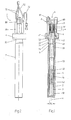
- the two vibrating bodies 2, 3 are above a Fastener 4 connected together.
- the Fastening device 4 also serves as a carrier or Base for attaching the level measuring device 1 in a housing opening with respect to its level to Watching container.
- the arrangement shown is in Essentially cylindrically symmetric about a central longitudinal axis X built around. Other cross-sectional shapes than circular Cross sections are, however, in principle also feasible.
- front-side elements which towards a container interior extend
- back elements such understood, which towards the container outside extend.
- the two vibrating bodies 2, 3 are characterized by an outer Vibration body 2 and an inner vibration body. 3 formed, both of which are substantially tubular are formed.
- the inner vibration body 3 can thereby in the back section 31 also except for a longitudinal passing through opening a narrowed Inner diameter of its interior 32, wherein the Interior 32 through the inner wall of the inner Vibration body 3 is limited.
- the two vibrating body 2, 3 open at the front or be formed closed.
- the outer vibrating body 2 is at the Fastening device via a back Attached connecting section.
- the back Verbingungsablie consists of a cylindrical Section 21, which extends from the back end of the outer Vibration body 2 extends in the axial direction and preferably by a taper or constriction 22 a elastic section is formed.
- the cylindrical one Section 21 is with the outer vibrating body. 2 preferably connected via a weld 24.
- the Constriction 22 goes in the illustrated embodiment in a direction perpendicular to the longitudinal axis X extending Connecting portion 23 via, which preferably together with the Einschürung 22 assumes the function of a membrane.
- the outside portion of the connection portion 23 is about, for example, a welded joint on the Fastener 4 attached.
- the inner vibrating body 3 is back with a Section 41 of the fastening device 4, in particular welded.
- the section 41 of Fastener 4 protrudes from the main body of the Fastening device 4 in the room, which by the cylindrical portion 21 for fixing the outer Vibration body 2 is formed.
- the section 41 of Fastening device 4 also has a constriction 42, wherein the portion 41 of the fastening device 4th by an appropriate choice of material and the constriction 42 as an elastic portion in the manner of a membrane for the inner vibration body 3 acts.
- the inner one Vibrating body 3 are vibrated, on the other hand, by the attachment over the section 41 on the fastening device 4 and the constriction 42 a Restoring force on the oscillating inner oscillating body 3 exerted so that its oscillation decays with time.
- a balance body 5 is inserted in the open interior 32 of the inner vibration body. 3 .
- the balance body 5 is in the direction of the central longitudinal axis X within the Interior 32 is arranged adjustable so that through Adjusting the balancing body 5 the vibration behavior of the inner vibration body to the vibration behavior of the outer vibration body can be adjusted.
- the vibration behavior of the inner Vibration body 3 on the vibration behavior of the outer Vibration body 2 in the ground state is also an altered one Tuning possible if the vibration behavior of a the vibrating body 2, 3, in particular the outer Vibration body 2, for example by adhering Material changed over time.
- the preferred vibration body 5 consists, as also shown in FIG. 3, a main body portion 50, which on the outside has an external thread 51.
- the external thread 51 is tuned to an internal thread 33, which inside in the wall of the interior 32 of the interior Vibration body 3 is formed.
- This allows the Balance body 5 in the interior 32 by screwing in front or rear direction to be adjusted.
- For adjusting is preferably a slot 52, which in an end face of the balance body 5 is formed.
- the Access to the slot 52 forms a passage or Access opening 6, which from the back through the different sections and components of Level measuring device 1 into the interior 32nd passes.
- Through the access opening 6 of the Manually adjusted adjustment body with a screwdriver become.
- the introduction of a corresponding suitable adjustment instrument with motor drive control possible, for example for an automated final adjustment of the complete and fully functional sensor.
- the balance body 5 also has an elastic Section 52 on.
- the elastic portion 52 has in relaxed state at least in a section one Outside diameter ds *, which is greater than one Inner diameter dgi of the cavity 32 is. To the elastic To introduce section into the cavity 32, the elastic portion 52 are therefore compressed an outer diameter less than or equal to Inner diameter dgi of the cavity 32. This is in the elastic portion 52 a elasticity slot 53rd educated.
- the elasticity slot 53 leads across the elastic portion 52 therethrough.
- the width of the Elastic slit 53 is so large that the outer circumference the elastic portion 52 is sufficiently compressed can be.
- the outer diameter ds * the elastic portion 52 in the relaxed state as well larger than the outer circumference dga * of the external thread 51 of the Main body portion 50 of the balance body fifth
- a balance body 5 in which the Transition region between the main body portion 50 and the elastic section 52 to a degree smaller than Thread depth of the external thread 51 is tapered, wherein the elastic portion is tapered from this point widened.
- the Drive and / or receiving device 7 is in Essentially from a housing 70 for receiving a actual drive and / or receiving device 71 and for receiving various fasteners and Connection cables 72.
- the actual drive and / or Receiving device is shown in the Embodiment of a rear drive unit 71 * and a front-side receiving unit 71 is formed.
- Central runs along the longitudinal axis X through the drive and / or receiving device 7 and by all in this Area arranged components the passage or Access opening 6, which by the drive and / or Receiving device 7 through a central access the fastening device 6 and the cavity 32 of the inner vibrating body 3 allows.
- the actual drive and / or receiving device 71 consists of a variety layered on top of each other arranged drive and / or receiving elements 73, in particular piezo elements, between each one Electrodes 74 are arranged.
- the electrodes 74 are with corresponding connection cables 72 connected to it Create voltages for generating a vibration or Dissipate voltages which by a received Vibration are generated.
- a sleeve 75 of an electric insulating material To avoid damage and increasing the hold and avoiding short circuits leads centrally through the drive and / or Receiving device 7, a sleeve 75 of an electric insulating material.
- the individual piezo elements 73 and Electrodes 74 and the sleeve 75 are between Fasteners, d. H.
- a Tensioning mechanism as a fastening device 8.
- This preferably consists of a transverse to the longitudinal direction extending fastener 80 also with a central through-hole 6, this being Fastener 80 rear across the drive and / or receiving device 7 extending tensioned.
- the clamping takes place, for example, with an arrangement Screws, threaded bolts and nuts 81 in per se known Way.
- the connecting element 81 for transmitting the vibrations of the Membrane 23 of the outer vibrating body 2 on the back or the rear fastening element 80 of the drive and / or receiving device 7 at least one Connecting element 81 on the rear wall of the membrane 23 to be fastened, said connecting element 81 through a corresponding passage opening 4 * in the Fastening device preferably frictionless passes.
- This connecting element 81 leads in addition to the Drive and / or receiving device 7 in the back Direction to the transverse fastener 80, such that a vibration of the membrane 23 via this Connecting element 81 and the rear fastener 80 to the rear of the drive and / or receiving device. 7 is transmitted.
- the fastener 80 via a Connecting element 81 against the fastening device 4 and in particular against the connecting portion 22, 23 of the tensioned outer vibrating body 2, wherein by the Distort the vibrations of the outer vibrating body. 2 at the back against the drive and / or receiving device 7 be transmitted.
- the mass of the Balancing body is preferably adjusted so that the Balance body with 100% dimensional accuracy of the components in the center of the open inner space 32 is to be arranged and thus by adjusting in the front or back direction a compensation of the vibration system is made possible. A additional anti-rotation is due to the clamping action of Screw itself no longer required.
- the material of the balance body can theoretically arbitrary be chosen, with a metal next to a relatively high Mass also offers the advantage of being heat resistant. The Use of non-heat-resistant plastic clamping coatings is therefore not advantageous required. Also, the adjustment is a mechanical Material removal on the vibrating diaphragm for the basic adjustment not necessary anymore.
- the central passage or access opening 6 Through the central passage or access opening 6 is a centric structure of the entire system possible, with a Adjustment by adjusting the balancing body 5 also in built-in state from the back of the Level gauge is enabled. advantageously, Also, only a single drive is needed to concentric around the central axis of the overall system is arranged and for the transmission of vibrations over a vibration transmitting section from or to the Vibrating bodies 2, 3 is advantageous to arrange.
- the Vibration transmission section 4 is in particular from the fastening device 4 and optionally further Fixing and intermediate elements of the drive and Receiving device 7. A match is thus without one Disassembly of rear components at any time easy possible.
Landscapes
- Physics & Mathematics (AREA)
- Acoustics & Sound (AREA)
- Electromagnetism (AREA)
- Thermal Sciences (AREA)
- Fluid Mechanics (AREA)
- General Physics & Mathematics (AREA)
- Apparatuses For Generation Of Mechanical Vibrations (AREA)
- Measuring Volume Flow (AREA)
- Geophysics And Detection Of Objects (AREA)
- Measurement Of Levels Of Liquids Or Fluent Solid Materials (AREA)
- Measurement Of Mechanical Vibrations Or Ultrasonic Waves (AREA)
Priority Applications (1)
| Application Number | Priority Date | Filing Date | Title |
|---|---|---|---|
| EP10010494A EP2273239A1 (fr) | 2004-02-27 | 2004-10-13 | Corps vibrant pour un capteur de niveau d'un liquide comprenant une vis de réglage pour modifier la fréquence de résonance |
Applications Claiming Priority (2)
| Application Number | Priority Date | Filing Date | Title |
|---|---|---|---|
| DE102004009495A DE102004009495B4 (de) | 2004-02-27 | 2004-02-27 | Abgleichkörper für eine Füllstandsmessvorrichtung |
| DE102004009495 | 2004-02-27 |
Publications (1)
| Publication Number | Publication Date |
|---|---|
| EP1568974A1 true EP1568974A1 (fr) | 2005-08-31 |
Family
ID=34745296
Family Applications (2)
| Application Number | Title | Priority Date | Filing Date |
|---|---|---|---|
| EP10010494A Withdrawn EP2273239A1 (fr) | 2004-02-27 | 2004-10-13 | Corps vibrant pour un capteur de niveau d'un liquide comprenant une vis de réglage pour modifier la fréquence de résonance |
| EP04024328A Withdrawn EP1568974A1 (fr) | 2004-02-27 | 2004-10-13 | Vis de réglage |
Family Applications Before (1)
| Application Number | Title | Priority Date | Filing Date |
|---|---|---|---|
| EP10010494A Withdrawn EP2273239A1 (fr) | 2004-02-27 | 2004-10-13 | Corps vibrant pour un capteur de niveau d'un liquide comprenant une vis de réglage pour modifier la fréquence de résonance |
Country Status (6)
| Country | Link |
|---|---|
| US (1) | US7131326B2 (fr) |
| EP (2) | EP2273239A1 (fr) |
| CN (1) | CN100593695C (fr) |
| DE (1) | DE102004009495B4 (fr) |
| HK (1) | HK1080137A1 (fr) |
| HU (1) | HU227252B1 (fr) |
Families Citing this family (13)
| Publication number | Priority date | Publication date | Assignee | Title |
|---|---|---|---|---|
| DE102008043764A1 (de) | 2008-11-14 | 2010-05-20 | Endress + Hauser Gmbh + Co. Kg | Vorrichtung zur Bestimmung und/oder Überwachung einer Prozessgröße |
| USD611860S1 (en) * | 2009-04-21 | 2010-03-16 | Wema-System As | Level sensor |
| USD611859S1 (en) * | 2009-04-21 | 2010-03-16 | Wema-System As | Level sensor |
| DE102012103165A1 (de) * | 2012-04-12 | 2013-10-17 | Endress + Hauser Gmbh + Co. Kg | Füllstandsmessgerät |
| EP3045880A1 (fr) * | 2015-01-14 | 2016-07-20 | VEGA Grieshaber KG | Système de mesure de niveau limite |
| CN104634419B (zh) * | 2015-02-03 | 2017-12-26 | 深圳计为自动化技术有限公司 | 振动式物料开关的质量块、振动装置及谐振频率调试方法 |
| DE102015122648B4 (de) | 2015-12-22 | 2025-07-31 | Vega Grieshaber Kg | Füllstandmessvorrichtung |
| EP3273210B1 (fr) * | 2016-07-18 | 2022-05-18 | VEGA Grieshaber KG | Détecteur de niveau à lames vibrantes et son procede de fabrication |
| DE102016125822A1 (de) | 2016-12-28 | 2018-06-28 | Vega Grieshaber Kg | Vibrationssensor |
| DE102017119714B4 (de) * | 2017-08-28 | 2022-01-05 | Vega Grieshaber Kg | Vibrationssensor |
| JP6979212B2 (ja) * | 2018-11-22 | 2021-12-08 | 株式会社マツシマメジャテック | 振動式レベルスイッチ |
| DE102021126093A1 (de) * | 2021-10-07 | 2023-04-13 | Endress+Hauser SE+Co. KG | Entkopplungseinheit für einen vibronischen Sensor |
| DE102024110947A1 (de) * | 2024-04-18 | 2025-10-23 | Endress+Hauser SE+Co. KG | Vibrationssensor und Verfahren zum Abgleichen eines Vibrationssensors |
Citations (4)
| Publication number | Priority date | Publication date | Assignee | Title |
|---|---|---|---|---|
| US4438981A (en) * | 1981-07-09 | 1984-03-27 | Intertractor Viehmann Gmbh & Co. | Hinge joint for a track chain |
| US4896536A (en) * | 1987-11-30 | 1990-01-30 | Vega Grieshaber Gmbh & Co. | Oscillation unit for filling level vibration limit switch |
| DE19651362C1 (de) * | 1996-12-10 | 1998-06-10 | Endress Hauser Gmbh Co | Vorrichtung zur Überwachung eines vorbestimmten Füllstands in einem Behälter |
| EP0949489A1 (fr) * | 1998-04-06 | 1999-10-13 | Nohken Inc. | Détecteur du niveau à vibrations |
Family Cites Families (11)
| Publication number | Priority date | Publication date | Assignee | Title |
|---|---|---|---|---|
| DE3416254C2 (de) * | 1984-05-02 | 1986-06-19 | VEGA Grieshaber GmbH & Co, 7620 Wolfach | Vorrichtung zur Feststellung eines bestimmten Füllstandes eines Füllgutes in einem Behälter |
| US4740726A (en) * | 1986-07-21 | 1988-04-26 | Nohken Inc. | Vibrator-type level sensor |
| DE3808481C2 (de) * | 1988-03-14 | 1997-11-27 | Endress Hauser Gmbh Co | Vorrichtung zur Feststellung eines bestimmten Füllstandes in einem Behälter |
| JP3008991B2 (ja) * | 1991-02-14 | 2000-02-14 | 株式会社ノーケン | 振動式レベル検出装置 |
| DE4203715C2 (de) * | 1992-02-08 | 1996-12-05 | Grieshaber Vega Kg | Vorrichtung zur Feststellung und/oder Überwachung eines vorbestimmten Füllstands in einem Behälter |
| CN2152932Y (zh) * | 1993-04-10 | 1994-01-12 | 徐大益 | 膨胀螺栓 |
| DE4318750C1 (de) * | 1993-06-05 | 1994-06-01 | Eberhard F Hermann | Vorrichtung zur Messung, Kontrolle und/oder Feststellung eines Füllstandes in einem Behälter |
| SE519554C2 (sv) * | 1999-04-14 | 2003-03-11 | Ericsson Telefon Ab L M | Skruvanordning samt trimanordning innefattande en sådan skruvanordning för trimning av ett kavitetsfilters frekvensförhållande eller kopplingsgrad |
| DE10131081A1 (de) * | 2001-06-27 | 2003-01-09 | Endress & Hauser Gmbh & Co Kg | Vorrichtung zur Bestimmung und/oder Überwachung des Füllstandes eines Mediums in einem Behälter |
| DE10318705A1 (de) * | 2003-04-24 | 2004-11-18 | Endress + Hauser Gmbh + Co. Kg | Vorrichtung zur Bestimmung und/oder Überwachung mindestens einer physikalischen oder chemischen Prozessgröße eines Mediums |
| DE10321025B4 (de) * | 2003-05-10 | 2005-07-28 | Eberhard Hermann | Vorrichtung zur Feststellung eines Füllstandes eines Füllgutes in einem Behälter |
-
2004
- 2004-02-27 DE DE102004009495A patent/DE102004009495B4/de not_active Expired - Lifetime
- 2004-10-13 EP EP10010494A patent/EP2273239A1/fr not_active Withdrawn
- 2004-10-13 EP EP04024328A patent/EP1568974A1/fr not_active Withdrawn
- 2004-11-22 HU HU0402411A patent/HU227252B1/hu not_active IP Right Cessation
- 2004-12-08 CN CN200410100681A patent/CN100593695C/zh not_active Expired - Fee Related
-
2005
- 2005-01-13 US US11/033,863 patent/US7131326B2/en not_active Expired - Lifetime
-
2006
- 2006-01-04 HK HK06100043.1A patent/HK1080137A1/zh unknown
Patent Citations (4)
| Publication number | Priority date | Publication date | Assignee | Title |
|---|---|---|---|---|
| US4438981A (en) * | 1981-07-09 | 1984-03-27 | Intertractor Viehmann Gmbh & Co. | Hinge joint for a track chain |
| US4896536A (en) * | 1987-11-30 | 1990-01-30 | Vega Grieshaber Gmbh & Co. | Oscillation unit for filling level vibration limit switch |
| DE19651362C1 (de) * | 1996-12-10 | 1998-06-10 | Endress Hauser Gmbh Co | Vorrichtung zur Überwachung eines vorbestimmten Füllstands in einem Behälter |
| EP0949489A1 (fr) * | 1998-04-06 | 1999-10-13 | Nohken Inc. | Détecteur du niveau à vibrations |
Also Published As
| Publication number | Publication date |
|---|---|
| HU227252B1 (hu) | 2010-12-28 |
| US7131326B2 (en) | 2006-11-07 |
| CN1661340A (zh) | 2005-08-31 |
| EP2273239A1 (fr) | 2011-01-12 |
| US20060021430A1 (en) | 2006-02-02 |
| HK1080137A1 (zh) | 2006-04-21 |
| CN100593695C (zh) | 2010-03-10 |
| HUP0402411A2 (en) | 2006-09-28 |
| HU0402411D0 (en) | 2005-01-28 |
| DE102004009495A1 (de) | 2005-09-15 |
| DE102004009495B4 (de) | 2009-09-24 |
Similar Documents
| Publication | Publication Date | Title |
|---|---|---|
| EP2031359B1 (fr) | Dispositif de mesure du niveau de remplissage destiné à la détermination et/ou la surveillance d'un niveau de remplissage | |
| EP1985975B1 (fr) | Débitmètre massique Coriolis | |
| DE102004009495B4 (de) | Abgleichkörper für eine Füllstandsmessvorrichtung | |
| DE1773815B2 (de) | Vorrichtung zur Feststellung des Erreichens eines vorbestimmten Füllstands in einem Behälter | |
| EP0848237A1 (fr) | Dispositif de surveillance d'un niveau prédéterminé de remplissage dans un réservoir | |
| DE4118793A1 (de) | Vorrichtung zur feststellung und/oder ueberwachung eines vorbestimmten fuellstandes in einem behaelter | |
| DE10318705A1 (de) | Vorrichtung zur Bestimmung und/oder Überwachung mindestens einer physikalischen oder chemischen Prozessgröße eines Mediums | |
| EP0751380A1 (fr) | Dispositif pour la détermination et/ou la surveillance d'un niveau prédéterminé dans un réservoir | |
| EP2639788B1 (fr) | Capteur ultrasonique | |
| EP0089336B1 (fr) | Mesure du niveau de remplissage | |
| DE3740598C2 (de) | Schwingeinheit für Füllstand-Vibrations-Grenzschalter | |
| DE3011603C2 (de) | Vorrichtung zur Feststellung eines bestimmten Füllstandes in einem Behälter | |
| DE3625779C2 (fr) | ||
| EP3713682B1 (fr) | Unité de vibration ultrasonore avec amortissement | |
| DE3808481C2 (de) | Vorrichtung zur Feststellung eines bestimmten Füllstandes in einem Behälter | |
| EP3056877B1 (fr) | Agencement de mesure de vibration | |
| DE102005044725B4 (de) | Membranschwinger zur Bestimmung und/oder Überwachung einer Prozessgröße eines Mediums in einem Behälter | |
| DE102015122648B4 (de) | Füllstandmessvorrichtung | |
| EP1644708A1 (fr) | Appareil de champ pour determiner et/ou surveiller une variable de processus | |
| DE10321025B4 (de) | Vorrichtung zur Feststellung eines Füllstandes eines Füllgutes in einem Behälter | |
| DE202017103324U1 (de) | Schwingungsdämpfer | |
| DE102004019228A1 (de) | Füllstands-Messvorrichtung | |
| DE102005053331A1 (de) | Vorrichtung zur Bestimmung und/oder Überwachung einer Prozessgröße | |
| DE102006058439A1 (de) | Kraftmessbolzen zur Messung mechanischer Spannungen | |
| DE69027044T2 (de) | Lastenmessanordnung |
Legal Events
| Date | Code | Title | Description |
|---|---|---|---|
| PUAI | Public reference made under article 153(3) epc to a published international application that has entered the european phase |
Free format text: ORIGINAL CODE: 0009012 |
|
| AK | Designated contracting states |
Kind code of ref document: A1 Designated state(s): AT BE BG CH CY CZ DE DK EE ES FI FR GB GR HU IE IT LI LU MC NL PL PT RO SE SI SK TR |
|
| AX | Request for extension of the european patent |
Extension state: AL HR LT LV MK |
|
| 17P | Request for examination filed |
Effective date: 20050920 |
|
| AKX | Designation fees paid |
Designated state(s): DE FR GB |
|
| 17Q | First examination report despatched |
Effective date: 20080102 |
|
| STAA | Information on the status of an ep patent application or granted ep patent |
Free format text: STATUS: THE APPLICATION IS DEEMED TO BE WITHDRAWN |
|
| 18D | Application deemed to be withdrawn |
Effective date: 20180130 |