EP1569250A2 - Transformateur de courant et ensemble comprenant un appareil électrique - Google Patents
Transformateur de courant et ensemble comprenant un appareil électrique Download PDFInfo
- Publication number
- EP1569250A2 EP1569250A2 EP05100925A EP05100925A EP1569250A2 EP 1569250 A2 EP1569250 A2 EP 1569250A2 EP 05100925 A EP05100925 A EP 05100925A EP 05100925 A EP05100925 A EP 05100925A EP 1569250 A2 EP1569250 A2 EP 1569250A2
- Authority
- EP
- European Patent Office
- Prior art keywords
- housing
- transducer
- electrical device
- current transformer
- converter
- Prior art date
- Legal status (The legal status is an assumption and is not a legal conclusion. Google has not performed a legal analysis and makes no representation as to the accuracy of the status listed.)
- Withdrawn
Links
Images

Classifications
-
- H—ELECTRICITY
- H01—ELECTRIC ELEMENTS
- H01F—MAGNETS; INDUCTANCES; TRANSFORMERS; SELECTION OF MATERIALS FOR THEIR MAGNETIC PROPERTIES
- H01F27/00—Details of transformers or inductances, in general
- H01F27/06—Mounting, supporting or suspending transformers, reactors or choke coils not being of the signal type
-
- H—ELECTRICITY
- H01—ELECTRIC ELEMENTS
- H01F—MAGNETS; INDUCTANCES; TRANSFORMERS; SELECTION OF MATERIALS FOR THEIR MAGNETIC PROPERTIES
- H01F27/00—Details of transformers or inductances, in general
- H01F27/02—Casings
-
- H—ELECTRICITY
- H01—ELECTRIC ELEMENTS
- H01F—MAGNETS; INDUCTANCES; TRANSFORMERS; SELECTION OF MATERIALS FOR THEIR MAGNETIC PROPERTIES
- H01F38/00—Adaptations of transformers or inductances for specific applications or functions
- H01F38/20—Instruments transformers
- H01F38/22—Instruments transformers for single phase AC
- H01F38/28—Current transformers
- H01F38/30—Constructions
-
- H—ELECTRICITY
- H01—ELECTRIC ELEMENTS
- H01F—MAGNETS; INDUCTANCES; TRANSFORMERS; SELECTION OF MATERIALS FOR THEIR MAGNETIC PROPERTIES
- H01F38/00—Adaptations of transformers or inductances for specific applications or functions
- H01F38/20—Instruments transformers
- H01F38/22—Instruments transformers for single phase AC
- H01F38/28—Current transformers
- H01F38/30—Constructions
- H01F2038/305—Constructions with toroidal magnetic core
-
- H—ELECTRICITY
- H01—ELECTRIC ELEMENTS
- H01F—MAGNETS; INDUCTANCES; TRANSFORMERS; SELECTION OF MATERIALS FOR THEIR MAGNETIC PROPERTIES
- H01F27/00—Details of transformers or inductances, in general
- H01F27/28—Coils; Windings; Conductive connections
- H01F27/30—Fastening or clamping coils, windings, or parts thereof together; Fastening or mounting coils or windings on core, casing, or other support
- H01F27/306—Fastening or mounting coils or windings on core, casing or other support
Definitions
- the invention relates to a measuring transducer, in particular current transformer, for an electrical device.
- a measuring transducer in particular current transformer
- an arrangement with such a transducer and an electrical device in particular current transformer
- Instrument transformers are transformers for connecting measuring instruments. To voltage converters, as they are usually in high voltage systems used to connect the connected meters protect voltmeters are connected. Power converter, as they are mostly used in low-voltage systems, serve the connection of ammeters.
- As information provider of the current transformer serves a coil which is a conductor concentrically surrounds an electrical device. by virtue of of the current flowing in the current conductor primary current is in the coil a voltage induces a secondary current as a measurement signal entails. In other words, one becomes the input AC proportional and according to the gear ratio lower output alternating current generated.
- Such current transformers find u. a. in modern switching devices, such as motor protection relays or soft starters, Use.
- the current transformers provide information about the operating current to the switching device, which thereby in the Location is moved, for example, in addition to its original tasks also to take over motor protection functions.
- the converters are glued into the housing of the switching device.
- the gluing takes place at the beginning of the assembly process, so that a later change of the current transformer type, For example, the use of a smaller size for a lower rated current, not possible.
- the object of the invention is to provide a simple yet secure Attaching a transducer to an electrical Device to allow. This task is performed by a transducer according to claim 1 or by an arrangement according to claim 6 solved.
- a basic idea of the invention is to provide a measuring transducer in one Transducer housing accommodate, without the use of additional Connection components, such as screws, for a direct connection to the device housing of a electrical device, such as a switching device, is trained.
- a direct connection to the device housing of a electrical device, such as a switching device.
- both the converter housing of the transducer as well as the device housing of the electrical device have corresponding connecting elements, which cooperate in the final assembly state and a safe Ensure connection of transducer and electrical device.
- These fasteners are according to the invention designed to form a snap or snap connection. This means that the transducer with the electric Device by simply plugging in, plugging in or plugging in is connected. Elaborate glands or other additional fastening devices are not required.
- Instrument transformer simply connected from the outside to the electrical device can be. Because of this easy mountability on the outside of the device is a mounting of the transducer possible at the end of the assembly process, so depending on the desired Purpose different current transformer types can be mounted.
- the Fastening elements designed such that the connection between the converter housing and the device housing by at least one Latching or snap-action nose is ensured, which with a corresponding fastener forms a rear handle. It has turned out to be particularly advantageous when the latching or snap-action nose is arranged on the device housing is while the counterpart, for example in shape a locking projection or a recess on the converter housing located. Since during assembly most of the transducer in Direction is directed to the electrical device is thus a particularly secure installation possible. Especially advantageous in this context it is when the catch or snap nose and / or the latching projections or recesses run-on slopes for easier locking.
- the device housing has in a further embodiment of the Invention, a receiving opening in which the converter housing rests in the final assembled state.
- the Instrument transformer for attachment to the electrical device in the Device housing introduced. It is particularly advantageous when complete insertion takes place so that the transducer in the final assembled state with the surface of the switching device essentially flush. This will be a even housing surface achieved, the one particularly flexible installation of the electrical device in different Mounting environments allows.
- the converter housing on the side, which when mounting on the electrical device to show, at least partially open.
- the converter housing at least part of the Transducer, preferably the coil in the transducer housing, does not completely enclose. This saves material and associated weight reduction possible.
- the opening in the converter housing is according to another embodiment the invention by a corresponding part closed the device housing in the final assembled state. With others Words only becomes by connecting the two housings the transducer completely enclosed. Closing the opening the converter housing serves at the same time for the production a sufficient voltage gap between the transducer coil and the corresponding power conductor of the electrical device.
- the Device housing clamping ribs for forming a tight fit of the Converter housing in the final assembled state. This will be a Particularly firm and play-free fit of the converter housing in Device housing ensured. This is required to get one Housing wear due to vibration, as due to the high Mass of the converter can occur, to avoid.
- the Transducer housing a formed like a bag housing element on, which for leading out a connecting line for connecting the transducer to measuring instruments, where the measuring or evaluation unit preferably in the electrical device is located.
- the housing pocket on the converter housing is assigned a corresponding receptacle in the device housing.
- the housing pocket also serves as a backup, so that a wrong construction of the transducer in the electrical device is excluded.
- the Transducer housing also has a mounting element for attaching a Accessory on.
- a mounting element for attaching a Accessory on. This may be, for example, a Cover to ensure protection against contact or act like that.
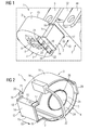
- the converter housing 3 which preferably consists of a Plastic material is made essentially consists from a cylindrical base element 4, in which the transducer components glued or poured.
- the converter housing 3 has an approximately centrally disposed Through opening 5 for a busbar 6 of the switching device 2 on.
- the passage opening 5 closes in the mounted position the switching device 2 opposite front side 7 of Transducer housing 3 with a slot-shaped Ausfuelö réelle 8 from. Above and below the Austechnologyö réelle 8 are in the converter housing Breakthroughs 9 provided for a cooling air flow.
- the current transformer 1 in Mounting direction 10 parallel to the busbar 6 on the Switching device 2 to led.
- a pocket-shaped Housing element On the lateral surface 11 of the base member 4 is a pocket-shaped Housing element molded.
- This case 12 has a rectangular plan and runs from the Front 7 of the converter housing 3 to the opposite, to the switching device 2 facing back 13 of the Transducer housing 3.
- the front side 14 of the housing pocket 12 is over with the lateral surface 11 of the base member 4 via Side surfaces 15 connected.
- At the back of the converter housing 13 3 facing ends of these side surfaces 15 are transverse to the mounting direction 10 facing locking projections 16 in Formed by webs.
- Switching device side have this Latching projections 16 chamfers 17 on.
- the towards the exit opening 8 facing front side 20 of the web 19 has a fastening hooks serving bar 21, while at the opposite Rear 22 of the web support struts 23 for reinforcement of the web 19 are formed.
- the converter housing 3 is open on the switching device side.
- the coil 24 of the current transformer 1 lies in the base element 4 and is on one towards the exit opening 8 slightly tapered bobbins 25 with circular Cross section arranged.
- the circular insertion opening 26 of the bobbin 25 forms the rear end of the Through opening 5 for the busbar. 6
- the housing pocket 12 is also open on the back. It serves to lead out a connecting line 27th with an electrical connector 28 for connection of the current transformer 1 to a control assembly (not shown) of the switching device 2 is used.
- a further, smaller housing pocket 29 is formed on the housing pocket 12 opposite side of the base member 4. This serves for a better management of the current transformer 1 when installed in the switching device 2.
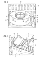
- a substantially circular receiving opening 32 for complete recording of the current transformer 1 is provided in the housing wall 30 of the device housing 31 of the switching device 2 .
- a truncated conical dome 33 as a counterpart to the coil carrier 25 arranged in the converter housing 3.
- the dome 33 has a Shooting mount 34 for the busbar 6, which in 3 is not yet mounted.
- the receiving opening 32 also has a laterally arranged, rectangular recess 37 for receiving the first housing pocket 12 and one on the opposite Side arranged rectangular recess 38 for receiving the second housing pocket 29, which also serves as a hedge serve.
- a resilient latching hook 40 On the narrow sides 39 of the recess 37 for the first housing pocket 12 is arranged in each case a resilient latching hook 40, the at his pointing in the direction of the device interior end has a latch 41. They show with run-on slopes 42 provided locking lugs 41 toward each other in the recess 32 inside.
- the device housing 31 in the area of his Receiving opening 32 a passage (not shown) for coming from the housing pocket 12 of the converter housing 3 Connecting line 27 and a corresponding mating connector (not shown).
- FIG 4 A further detailed representation of the receiving opening 32 and a Latching hook 40 gives FIG 4, in which a current transformer 1 at Insertion into the receiving opening 32 of a switching device 2 is shown.
- FIG. 5 finally gives a perspective view Switching device 2 with three busbars, taking on the viewer removed, rear busbar already a first Current transformer 1 'is placed.
- This first current transformer 1 ' is in its final assembly position, in which its front 7 'with the surface 43 of the device housing 31 terminates. Only the one from the front 7 'of the current transformer 1 'projecting web 19' protrudes with fastening hooks out.
- the middle busbar 44 remains free.
- the viewer nearest arranged busbar 6 is just a current transformer 1 is placed.
- the two out of the housing surface 43 protruding webs 19, 19 'then form a fastening device for a cover in the form of a contact protection cap or the like (not shown).
Landscapes
- Engineering & Computer Science (AREA)
- Power Engineering (AREA)
- Transformers For Measuring Instruments (AREA)
- Measuring Instrument Details And Bridges, And Automatic Balancing Devices (AREA)
Applications Claiming Priority (2)
| Application Number | Priority Date | Filing Date | Title |
|---|---|---|---|
| DE102004008978 | 2004-02-24 | ||
| DE102004008978 | 2004-02-24 |
Publications (2)
| Publication Number | Publication Date |
|---|---|
| EP1569250A2 true EP1569250A2 (fr) | 2005-08-31 |
| EP1569250A3 EP1569250A3 (fr) | 2007-12-05 |
Family
ID=34745263
Family Applications (1)
| Application Number | Title | Priority Date | Filing Date |
|---|---|---|---|
| EP05100925A Withdrawn EP1569250A3 (fr) | 2004-02-24 | 2005-02-09 | Transformateur de courant et ensemble comprenant un appareil électrique |
Country Status (1)
| Country | Link |
|---|---|
| EP (1) | EP1569250A3 (fr) |
Cited By (5)
| Publication number | Priority date | Publication date | Assignee | Title |
|---|---|---|---|---|
| AT502659B1 (de) * | 2005-10-11 | 2007-05-15 | Fronius Int Gmbh | Stromwandler |
| DE102007044632B3 (de) * | 2007-09-19 | 2009-02-26 | Siemens Ag | Ansteuerbaugruppe eines Schaltgerätes sowie Schaltgerät |
| CN105304304A (zh) * | 2015-10-26 | 2016-02-03 | 常州欧瑞电气有限公司 | 自供电微机保护装置用电流互感器 |
| DE102015205632A1 (de) * | 2015-03-27 | 2016-09-29 | Siemens Aktiengesellschaft | Stromwandler und Strommesseinrichtung |
| WO2026021029A1 (fr) * | 2024-07-23 | 2026-01-29 | 上海摩瓦新能源科技有限公司 | Ensemble transformateur, transformateur et convertisseur de puissance |
Family Cites Families (1)
| Publication number | Priority date | Publication date | Assignee | Title |
|---|---|---|---|---|
| US6008711A (en) * | 1998-01-09 | 1999-12-28 | Siemens Power Transmission & Distribution | Method and arrangement for securing a current transformer to an electric utility meter housing |
-
2005
- 2005-02-09 EP EP05100925A patent/EP1569250A3/fr not_active Withdrawn
Cited By (6)
| Publication number | Priority date | Publication date | Assignee | Title |
|---|---|---|---|---|
| AT502659B1 (de) * | 2005-10-11 | 2007-05-15 | Fronius Int Gmbh | Stromwandler |
| DE102007044632B3 (de) * | 2007-09-19 | 2009-02-26 | Siemens Ag | Ansteuerbaugruppe eines Schaltgerätes sowie Schaltgerät |
| DE102015205632A1 (de) * | 2015-03-27 | 2016-09-29 | Siemens Aktiengesellschaft | Stromwandler und Strommesseinrichtung |
| CN105304304A (zh) * | 2015-10-26 | 2016-02-03 | 常州欧瑞电气有限公司 | 自供电微机保护装置用电流互感器 |
| CN105304304B (zh) * | 2015-10-26 | 2017-07-04 | 常州欧瑞电气股份有限公司 | 自供电微机保护装置用电流互感器 |
| WO2026021029A1 (fr) * | 2024-07-23 | 2026-01-29 | 上海摩瓦新能源科技有限公司 | Ensemble transformateur, transformateur et convertisseur de puissance |
Also Published As
| Publication number | Publication date |
|---|---|
| EP1569250A3 (fr) | 2007-12-05 |
Similar Documents
| Publication | Publication Date | Title |
|---|---|---|
| EP2614515B1 (fr) | Appareil de commutation et accessoire du côté connexion | |
| EP0248181A1 (fr) | Boîte de fusibles et de distribution pour véhicules à moteur | |
| EP1290759A1 (fr) | Borne de connexion | |
| DE10323550A1 (de) | Sicherungsdose für ein Fahrzeug | |
| EP2385540B1 (fr) | Dispositif de réception de sécurité, notamment pour boîtes de raccordement d'installations photovoltaïques | |
| DE102007051419A1 (de) | NH-Sicherungslasttrenner mit Stromwandler | |
| DE3739051C2 (de) | Sicherung | |
| DE2724939B2 (de) | Schaltgerät, insbesondere elektronisches, berührungslos arbeitendes Schaltgerät | |
| DE2511385C3 (de) | Elektrische Anschlußklemme | |
| DE9012881U1 (de) | Anordnung eines Varistors in einem Gehäuse | |
| EP1569250A2 (fr) | Transformateur de courant et ensemble comprenant un appareil électrique | |
| EP3309904B1 (fr) | Logement de raccordement d'au moins un toron de câbles d'un câble | |
| DE60104027T2 (de) | Elektrischer Energiezähler | |
| DE10131739B4 (de) | Stromwandler | |
| EP0976310B1 (fr) | Appareil electrique a deux capots de boitier identiques | |
| DE102005056214B3 (de) | Vorrichtung zum Führen von Kabeln oder Leitungen | |
| DE29823870U1 (de) | Kasten-Gehäuse zur Aufnahme mindestens einer Elektronikplatine | |
| DE29903000U1 (de) | Isoliergehäuse für Verteilerklemme | |
| DE69834897T2 (de) | Verwechslungsschutzanordnung für elektrische Schaltgeräte, insbesondere für Leistungsschalter und Differenzstromschutzschalter | |
| DE19846196A1 (de) | Verbinder für eine Fahrzeug-Batterie | |
| DE2900357A1 (de) | Ueberbrueckungseinrichtung fuer einen elektrozaehler | |
| DE19854584B4 (de) | Elektrische Installationsgeräte, insbesondere Schutzkontaktsteckdosenanordnungen | |
| DE60006838T2 (de) | Elektrische anschlussvorrichtung für leistungsschalter | |
| DE4327172C2 (de) | Vorrichtung zur lösbaren Befestigung mindestens eines elektrischen Bauteils an einer Profilschiene | |
| DE3025129A1 (de) | Schnellbefestigungsvorrichtung |
Legal Events
| Date | Code | Title | Description |
|---|---|---|---|
| PUAI | Public reference made under article 153(3) epc to a published international application that has entered the european phase |
Free format text: ORIGINAL CODE: 0009012 |
|
| AK | Designated contracting states |
Kind code of ref document: A2 Designated state(s): AT BE BG CH CY CZ DE DK EE ES FI FR GB GR HU IE IS IT LI LT LU MC NL PL PT RO SE SI SK TR |
|
| AX | Request for extension of the european patent |
Extension state: AL BA HR LV MK YU |
|
| PUAL | Search report despatched |
Free format text: ORIGINAL CODE: 0009013 |
|
| AK | Designated contracting states |
Kind code of ref document: A3 Designated state(s): AT BE BG CH CY CZ DE DK EE ES FI FR GB GR HU IE IS IT LI LT LU MC NL PL PT RO SE SI SK TR |
|
| AX | Request for extension of the european patent |
Extension state: AL BA HR LV MK YU |
|
| RIC1 | Information provided on ipc code assigned before grant |
Ipc: H01R 13/66 20060101ALI20071026BHEP Ipc: H01F 27/06 20060101ALI20071026BHEP Ipc: H01F 27/02 20060101ALI20071026BHEP Ipc: H01F 38/30 20060101AFI20050512BHEP |
|
| 17P | Request for examination filed |
Effective date: 20080110 |
|
| AKX | Designation fees paid |
Designated state(s): DE FR SE |
|
| 17Q | First examination report despatched |
Effective date: 20081121 |
|
| STAA | Information on the status of an ep patent application or granted ep patent |
Free format text: STATUS: THE APPLICATION IS DEEMED TO BE WITHDRAWN |
|
| 18D | Application deemed to be withdrawn |
Effective date: 20090402 |