EP1570178B1 - Pompe haute pression pour dispositif d'injection de carburant de moteur a combustion interne - Google Patents
Pompe haute pression pour dispositif d'injection de carburant de moteur a combustion interne Download PDFInfo
- Publication number
- EP1570178B1 EP1570178B1 EP03812124A EP03812124A EP1570178B1 EP 1570178 B1 EP1570178 B1 EP 1570178B1 EP 03812124 A EP03812124 A EP 03812124A EP 03812124 A EP03812124 A EP 03812124A EP 1570178 B1 EP1570178 B1 EP 1570178B1
- Authority
- EP
- European Patent Office
- Prior art keywords
- ring
- pressure pump
- solid lubricant
- drive shaft
- pump
- Prior art date
- Legal status (The legal status is an assumption and is not a legal conclusion. Google has not performed a legal analysis and makes no representation as to the accuracy of the status listed.)
- Expired - Lifetime
Links
Images


Classifications
-
- F—MECHANICAL ENGINEERING; LIGHTING; HEATING; WEAPONS; BLASTING
- F04—POSITIVE - DISPLACEMENT MACHINES FOR LIQUIDS; PUMPS FOR LIQUIDS OR ELASTIC FLUIDS
- F04B—POSITIVE-DISPLACEMENT MACHINES FOR LIQUIDS; PUMPS
- F04B1/00—Multi-cylinder machines or pumps characterised by number or arrangement of cylinders
- F04B1/04—Multi-cylinder machines or pumps characterised by number or arrangement of cylinders having cylinders in star- or fan-arrangement
- F04B1/0404—Details or component parts
- F04B1/0413—Cams
-
- F—MECHANICAL ENGINEERING; LIGHTING; HEATING; WEAPONS; BLASTING
- F02—COMBUSTION ENGINES; HOT-GAS OR COMBUSTION-PRODUCT ENGINE PLANTS
- F02M—SUPPLYING COMBUSTION ENGINES IN GENERAL WITH COMBUSTIBLE MIXTURES OR CONSTITUENTS THEREOF
- F02M59/00—Pumps specially adapted for fuel-injection and not provided for in groups F02M39/00 -F02M57/00, e.g. rotary cylinder-block type of pumps
- F02M59/02—Pumps specially adapted for fuel-injection and not provided for in groups F02M39/00 -F02M57/00, e.g. rotary cylinder-block type of pumps of reciprocating-piston or reciprocating-cylinder type
- F02M59/10—Pumps specially adapted for fuel-injection and not provided for in groups F02M39/00 -F02M57/00, e.g. rotary cylinder-block type of pumps of reciprocating-piston or reciprocating-cylinder type characterised by the piston-drive
- F02M59/102—Mechanical drive, e.g. tappets or cams
-
- F—MECHANICAL ENGINEERING; LIGHTING; HEATING; WEAPONS; BLASTING
- F02—COMBUSTION ENGINES; HOT-GAS OR COMBUSTION-PRODUCT ENGINE PLANTS
- F02M—SUPPLYING COMBUSTION ENGINES IN GENERAL WITH COMBUSTIBLE MIXTURES OR CONSTITUENTS THEREOF
- F02M63/00—Other fuel-injection apparatus having pertinent characteristics not provided for in groups F02M39/00 - F02M57/00 or F02M67/00; Details, component parts, or accessories of fuel-injection apparatus, not provided for in, or of interest apart from, the apparatus of groups F02M39/00 - F02M61/00 or F02M67/00; Combination of fuel pump with other devices, e.g. lubricating oil pump
- F02M63/0001—Fuel-injection apparatus with specially arranged lubricating system, e.g. by fuel oil
-
- F—MECHANICAL ENGINEERING; LIGHTING; HEATING; WEAPONS; BLASTING
- F04—POSITIVE - DISPLACEMENT MACHINES FOR LIQUIDS; PUMPS FOR LIQUIDS OR ELASTIC FLUIDS
- F04B—POSITIVE-DISPLACEMENT MACHINES FOR LIQUIDS; PUMPS
- F04B1/00—Multi-cylinder machines or pumps characterised by number or arrangement of cylinders
- F04B1/04—Multi-cylinder machines or pumps characterised by number or arrangement of cylinders having cylinders in star- or fan-arrangement
- F04B1/0404—Details or component parts
- F04B1/0426—Arrangements for pressing the pistons against the actuated cam; Arrangements for connecting the pistons to the actuated cam
-
- F—MECHANICAL ENGINEERING; LIGHTING; HEATING; WEAPONS; BLASTING
- F04—POSITIVE - DISPLACEMENT MACHINES FOR LIQUIDS; PUMPS FOR LIQUIDS OR ELASTIC FLUIDS
- F04B—POSITIVE-DISPLACEMENT MACHINES FOR LIQUIDS; PUMPS
- F04B1/00—Multi-cylinder machines or pumps characterised by number or arrangement of cylinders
- F04B1/04—Multi-cylinder machines or pumps characterised by number or arrangement of cylinders having cylinders in star- or fan-arrangement
- F04B1/053—Multi-cylinder machines or pumps characterised by number or arrangement of cylinders having cylinders in star- or fan-arrangement with actuating or actuated elements at the inner ends of the cylinders
-
- F—MECHANICAL ENGINEERING; LIGHTING; HEATING; WEAPONS; BLASTING
- F02—COMBUSTION ENGINES; HOT-GAS OR COMBUSTION-PRODUCT ENGINE PLANTS
- F02M—SUPPLYING COMBUSTION ENGINES IN GENERAL WITH COMBUSTIBLE MIXTURES OR CONSTITUENTS THEREOF
- F02M63/00—Other fuel-injection apparatus having pertinent characteristics not provided for in groups F02M39/00 - F02M57/00 or F02M67/00; Details, component parts, or accessories of fuel-injection apparatus, not provided for in, or of interest apart from, the apparatus of groups F02M39/00 - F02M61/00 or F02M67/00; Combination of fuel pump with other devices, e.g. lubricating oil pump
- F02M63/02—Fuel-injection apparatus having several injectors fed by a common pumping element, or having several pumping elements feeding a common injector; Fuel-injection apparatus having provisions for cutting-out pumps, pumping elements, or injectors; Fuel-injection apparatus having provisions for variably interconnecting pumping elements and injectors alternatively
- F02M63/0225—Fuel-injection apparatus having a common rail feeding several injectors ; Means for varying pressure in common rails; Pumps feeding common rails
-
- F—MECHANICAL ENGINEERING; LIGHTING; HEATING; WEAPONS; BLASTING
- F05—INDEXING SCHEMES RELATING TO ENGINES OR PUMPS IN VARIOUS SUBCLASSES OF CLASSES F01-F04
- F05C—INDEXING SCHEME RELATING TO MATERIALS, MATERIAL PROPERTIES OR MATERIAL CHARACTERISTICS FOR MACHINES, ENGINES OR PUMPS OTHER THAN NON-POSITIVE-DISPLACEMENT MACHINES OR ENGINES
- F05C2203/00—Non-metallic inorganic materials
- F05C2203/08—Ceramics; Oxides
- F05C2203/0804—Non-oxide ceramics
- F05C2203/0808—Carbon, e.g. graphite
-
- F—MECHANICAL ENGINEERING; LIGHTING; HEATING; WEAPONS; BLASTING
- F05—INDEXING SCHEMES RELATING TO ENGINES OR PUMPS IN VARIOUS SUBCLASSES OF CLASSES F01-F04
- F05C—INDEXING SCHEME RELATING TO MATERIALS, MATERIAL PROPERTIES OR MATERIAL CHARACTERISTICS FOR MACHINES, ENGINES OR PUMPS OTHER THAN NON-POSITIVE-DISPLACEMENT MACHINES OR ENGINES
- F05C2203/00—Non-metallic inorganic materials
- F05C2203/08—Ceramics; Oxides
- F05C2203/0804—Non-oxide ceramics
- F05C2203/0856—Sulfides
- F05C2203/086—Sulfides of molybdenum
-
- F—MECHANICAL ENGINEERING; LIGHTING; HEATING; WEAPONS; BLASTING
- F05—INDEXING SCHEMES RELATING TO ENGINES OR PUMPS IN VARIOUS SUBCLASSES OF CLASSES F01-F04
- F05C—INDEXING SCHEME RELATING TO MATERIALS, MATERIAL PROPERTIES OR MATERIAL CHARACTERISTICS FOR MACHINES, ENGINES OR PUMPS OTHER THAN NON-POSITIVE-DISPLACEMENT MACHINES OR ENGINES
- F05C2203/00—Non-metallic inorganic materials
- F05C2203/08—Ceramics; Oxides
- F05C2203/0865—Oxide ceramics
- F05C2203/0882—Carbon, e.g. graphite
-
- F—MECHANICAL ENGINEERING; LIGHTING; HEATING; WEAPONS; BLASTING
- F05—INDEXING SCHEMES RELATING TO ENGINES OR PUMPS IN VARIOUS SUBCLASSES OF CLASSES F01-F04
- F05C—INDEXING SCHEME RELATING TO MATERIALS, MATERIAL PROPERTIES OR MATERIAL CHARACTERISTICS FOR MACHINES, ENGINES OR PUMPS OTHER THAN NON-POSITIVE-DISPLACEMENT MACHINES OR ENGINES
- F05C2225/00—Synthetic polymers, e.g. plastics; Rubber
- F05C2225/04—PTFE [PolyTetraFluorEthylene]
-
- F—MECHANICAL ENGINEERING; LIGHTING; HEATING; WEAPONS; BLASTING
- F05—INDEXING SCHEMES RELATING TO ENGINES OR PUMPS IN VARIOUS SUBCLASSES OF CLASSES F01-F04
- F05C—INDEXING SCHEME RELATING TO MATERIALS, MATERIAL PROPERTIES OR MATERIAL CHARACTERISTICS FOR MACHINES, ENGINES OR PUMPS OTHER THAN NON-POSITIVE-DISPLACEMENT MACHINES OR ENGINES
- F05C2251/00—Material properties
- F05C2251/14—Self lubricating materials; Solid lubricants
-
- F—MECHANICAL ENGINEERING; LIGHTING; HEATING; WEAPONS; BLASTING
- F05—INDEXING SCHEMES RELATING TO ENGINES OR PUMPS IN VARIOUS SUBCLASSES OF CLASSES F01-F04
- F05C—INDEXING SCHEME RELATING TO MATERIALS, MATERIAL PROPERTIES OR MATERIAL CHARACTERISTICS FOR MACHINES, ENGINES OR PUMPS OTHER THAN NON-POSITIVE-DISPLACEMENT MACHINES OR ENGINES
- F05C2253/00—Other material characteristics; Treatment of material
- F05C2253/12—Coating
Definitions
- the invention relates to a high-pressure pump for a fuel injection device of an internal combustion engine according to the preamble of claim 1.
- Such a high-pressure pump is through the EP 0 851120 A known.
- This high-pressure pump has a drive shaft and at least one pump element.
- the pump element has a pump piston driven by the drive shaft in a lifting movement.
- On an eccentric to the axis of rotation arranged portion of the drive shaft a ring is rotatably mounted, on which the pump piston is supported via a support member.
- the ring and / or the support element has a multiplicity of microwells at least in its contact region, and a solid lubricant layer is applied to the ring and / or the support element at least in its contact region.
- the microwells are present due to the surface roughness, but not specifically introduced into the surface. As a result, the effect of the microwells for receiving the solid lubricant layer or fuel may not be sufficient, so that in the production of very high pressures and low lubricating effect of the fuel sufficient life of the high pressure pump is not achieved.
- a high-pressure pump is also known in which a solid lubricating layer is applied to the ring and / or the support element in the contact region. However, no deliberately introduced microwells are provided.
- the high pressure pump according to the invention with the features of claim 1 has the advantage that the wear resistance of the ring and the support member is improved such that the high pressure pump reaches a sufficient life even in the production of very high pressures and low lubricity of the fuel.
- FIG. 1 a high-pressure pump in a longitudinal section.
- FIG. 2 the high pressure pump in a cross section along line II-II in FIG. 1 .
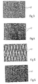
- FIG. 3 one in FIG. 2 labeled III section of the high-pressure pump with a first embodiment of microwells and the FIGS. 4 to 6 further versions of micro-forgings.
- FIGS. 1 to 6 is a high-pressure pump for a fuel injection device of an internal combustion engine, for example, a motor vehicle shown, which is designed as a radial piston pump.
- the high-pressure pump has a housing 10 in which a drive shaft 12 is rotatably mounted about an axis 13.
- a drive shaft 12 is rotatably mounted about an axis 13.
- the drive shaft 12 has an eccentric to its axis of rotation 13 formed shaft portion 16 on which a ring 18 is rotatably mounted.
- the pump elements 14 each have a pump piston 20, which is displaceably guided in an at least approximately radially to the rotational axis 13 of the drive shaft 12 extending cylinder bore 22.
- the pump piston 20 of each pump element 14 is supported with its piston foot 21 via a support member 24 on the ring 18.
- the piston 21 can be held by a spring 26, which is supported on the one hand on the housing 10 and on the other hand via a spring plate 23 on the support member 24 in abutment with the support member 24 and via this on the ring 18.
- the support member 24 may be formed, for example, as a support plate or as a plunger.
- a pump working chamber 28 is limited, which can be connected by an opening into the pump working chamber 28 inlet valve 30 with a fuel supply, prevails in the low pressure.
- the pump working chamber 28 can also be connected to the reservoir by means of an outlet valve 32 which opens towards the reservoir.
- the ring 18 has corresponding to the number of pump elements 14 on its outer side flats 34 on which the respective support member 24 abuts.
- the ring 18 and the support elements 24 are loaded by the cyclic loading and unloading of the pump piston 20 at their delivery stroke and suction stroke by different high pressure forces in the contact area between the support members 24 and the ring 18 act.
- the amount of fuel delivered by the high-pressure pump can be adapted to the requirements of the internal combustion engine.
- the feed of fuel into the pump working spaces 28 can be limited such that they are only partially filled. This can be done for example by means of a suction throttling in the inlet to the pump working spaces 28.
- a partial filling of the pump working chambers 28 occur in addition beating loads of the ring 18 and the support members 24, since the fuel delivery and thus the pressure load of the ring 18 and the support elements 24 takes place only after a partial idle stroke of the pump piston 20.
- a solid lubricant layer 40 is applied on its outer side at least on the flats 34, which represent the contact area to the support elements 24.
- the ring 18 also has on its outer side at least at the flats 34 and thus in the contact region to the support members 24 a plurality of microwells 42 which in the FIGS. 3 to 6 are shown enlarged.
- the ring 18 is preferably made of steel.
- the microwells 42 may, for example, as in FIG. 3 may be formed as wells that are evenly or irregularly distributed over the surface of the flats 34 of the ring 18 are arranged.
- the microwells 42 may alternatively also as in FIG. 4 shown formed as at least approximately straight grooves extending in the longitudinal or transverse direction or with any other orientation over the surface of the flats 34 of the ring 18.
- the microwells 42 may alternatively also as in FIG. 5 represented as crossing grooves may be formed, which extend over the surface of the flats 34 of the ring 18.
- the microwells 42 may also alternatively as in FIG. 6 illustrated as formed at least approximately circular segment-shaped grooves which are at least approximately concentric with each other over the surface of the flats 34 of the ring 18 are arranged distributed.
- a combination of the different embodiments of the microwells 42 discussed above may also be used.
- the microwells 42 preferably have a depth of about 2 to 30 microns, a width of about 15 to 30 microns and are spaced from each other at a distance of about 30 to 150 microns.
- the microwells 42 may be introduced into the surface of the flats 34 of the ring 18 by known machining techniques such as laser fabrication, hard turning, spark erosion or lithopraphic techniques.
- the solid lubricant layer 40 is applied to the surface of the flats 34 of the ring 18 and may cover the entire area, not only the microwells 42 but also the raised areas therebetween. In the surface of the solid lubricant layer 40 while the Microwaves 42 may be shown as depressions accordingly. In the recesses of the solid lubricant layer 40, fuel may accumulate, by which the lubrication between the ring 18 and the support members 24 is improved. At the beginning of the operation of the high-pressure pump, the solid lubricant layer 40 is present between the contact regions of the ring 18 and the support elements 24 and facilitates the shrinkage of the high-pressure pump, the solid lubricant layer 40 being removed during operation of the high-pressure pump.
- the solid lubricant layer 40 is present only in the microwells 42. As the ring 18 continues to wear, further solid lubricant continuously exits the microwells 42 and improves lubrication between the ring 18 and the support members 24.
- the thickness of the solid lubricant layer 40 is, for example, between 10 .mu.m and 20 .mu.m in its initial state.
- the solid lubricant layer 40 is applied to the ring 18 and then the microwells 42 are produced. In this case, there is no solid lubricant in the microwells 42, but these have the effect of accumulating in this fuel, which improves the lubrication between the ring 18 and the support members 24.
- the solid lubricant layer 40 is introduced only into the microwells 42 and that the raised areas lying between them have no solid lubricant layer 40.
- the solid lubricant layer 40 only partially fills the microwells 42 in the direction of their depth.
- fuel may accumulate in the microwells 42, improving the lubrication between the ring 18 and the support members 24.
- the depth of the microwells 42 decreases due to the wear, so that the solid lubricant gradually leaks out of them and then improves the lubrication between the ring 18 and the support members 24.
- the solid lubricant layer 40 consists of a binder material, are embedded in the solid lubricant particles.
- the solid lubricant layer 40 may be applied to the ring 18, for example, in the form of a liquid paint or other known application techniques.
- the binder material may consist of organic or inorganic compounds.
- the use of inorganic compounds for the binder material offers the advantage over organic compounds of a higher temperature resistance.
- the use of organic compounds for the binder material offers the advantage of better corrosion resistance over inorganic compounds.
- the choice of binder material is based on the requirements for temperature resistance and fuel resistance.
- the solid lubricant particles are present in the binder material uniformly as particles in a size of a few microns, preferably between about 3 and 8 microns in diameter.
- polytetrafluoroethylene or graphite or molybdenum disulfide can be used as solid lubricants, wherein a mixture of these substances can be used.
- a mixture of polytetrafluoroethylene and molybdenum disulfide allows a low coefficient of friction between the ring 18 and the support elements 24.
- a chemical pretreatment of the surface of the ring 18 may take place, for example phosphating, whereby an adhesion-promoting intermediate layer 44 is produced.
- This intermediate layer is to be applied in such a way that it does not level the microwells 42.
- the thickness of the intermediate layer should be at most about 20% of the depth of the microwells 42.
- the support elements 24 may be provided in their contact area with the ring 18 with a corresponding solid lubricating layer 40 and micro-recesses 42 as described above.
Landscapes
- Engineering & Computer Science (AREA)
- Mechanical Engineering (AREA)
- General Engineering & Computer Science (AREA)
- Chemical & Material Sciences (AREA)
- Combustion & Propulsion (AREA)
- Fuel-Injection Apparatus (AREA)
- Details Of Reciprocating Pumps (AREA)
- Reciprocating Pumps (AREA)
Abstract
Claims (6)
- Pompe haute pression pour un dispositif d'injection de carburant d'un moteur à combustion interne, comprenant un arbre d'entraînement (12), au moins un élément de pompe (14), qui présente un piston de pompe (20) entraîné dans un mouvement de va-et-vient par l'arbre d'entraînement (12), une bague (18) étant montée à rotation sur une portion (16) de l'arbre d'entraînement (12) disposée de manière excentrique par rapport à son axe de rotation (13), sur laquelle bague s'appuie le piston de pompe (20) par le biais d'un élément de support (24), la bague (18) et/ou l'élément de support (24) présentant au moins dans sa/leur région de contact une pluralité de renfoncements microscopiques (42) et au moins dans sa/leur région de contact, une couche de lubrifiant solide (40) étant appliquée sur la bague (18) et/ou sur l'élément de support (24), caractérisée en ce que les renfoncements microscopiques (42) présentent une profondeur de 2 à 30 µm, une largeur de 15 à 30 µm et un espacement les uns des autres de 30 à 150 µm, et en ce que les renfoncements microscopiques (42) sont réalisés sous forme de petits creux ou de rainures.
- Pompe haute pression selon la revendication 1, caractérisée en ce que les rainures se croisent.
- Pompe haute pression selon la revendication 1, caractérisée en ce que les rainures sont réalisées au moins approximativement en forme de segments de cercle.
- Pompe haute pression selon l'une quelconque des revendications précédentes, caractérisée en ce que la couche de lubrifiant solide (40) contient du polytétrafluoroéthylène et/ou du graphite et/ou du sulfure de molybdène.
- Pompe haute pression selon l'une quelconque des revendications précédentes, caractérisée en ce que la couche de lubrifiant solide (40) présente un liant dans lequel des particules de lubrifiant solide sont incorporées de manière répartie uniformément.
- Pompe haute pression selon l'une quelconque des revendications précédentes, caractérisée en ce qu'entre la surface de la bague (18) et/ou de l'élément de support (24) et la couche de lubrifiant solide (40) est disposée une couche intermédiaire (44) promotrice d'adhésion.
Applications Claiming Priority (3)
| Application Number | Priority Date | Filing Date | Title |
|---|---|---|---|
| DE10256528A DE10256528A1 (de) | 2002-12-04 | 2002-12-04 | Hochdruckpumpe für eine Kraftstoffeinspritzeinrichtung einer Brennkraftmaschine |
| DE10256528 | 2002-12-04 | ||
| PCT/DE2003/002703 WO2004051084A1 (fr) | 2002-12-04 | 2003-08-11 | Pompe haute pression pour dispositif d'injection de carburant de moteur a combustion interne |
Publications (2)
| Publication Number | Publication Date |
|---|---|
| EP1570178A1 EP1570178A1 (fr) | 2005-09-07 |
| EP1570178B1 true EP1570178B1 (fr) | 2011-06-08 |
Family
ID=32335940
Family Applications (1)
| Application Number | Title | Priority Date | Filing Date |
|---|---|---|---|
| EP03812124A Expired - Lifetime EP1570178B1 (fr) | 2002-12-04 | 2003-08-11 | Pompe haute pression pour dispositif d'injection de carburant de moteur a combustion interne |
Country Status (6)
| Country | Link |
|---|---|
| US (1) | US7278348B2 (fr) |
| EP (1) | EP1570178B1 (fr) |
| JP (1) | JP2006509142A (fr) |
| CN (1) | CN100557234C (fr) |
| DE (1) | DE10256528A1 (fr) |
| WO (1) | WO2004051084A1 (fr) |
Families Citing this family (18)
| Publication number | Priority date | Publication date | Assignee | Title |
|---|---|---|---|---|
| DE20313014U1 (de) * | 2003-08-21 | 2004-12-23 | Robert Bosch Gmbh | Hochdruckpumpe für eine Kraftstoffeinspritzeinrichtung einer Brennkraftmaschine |
| DE102004041764A1 (de) * | 2004-08-28 | 2006-03-02 | Robert Bosch Gmbh | Hochdruckpumpe für eine Kraftstoffeinspritzeinrichtung einer Brennkraftmaschine |
| DE102007044499A1 (de) * | 2007-09-18 | 2009-03-19 | Robert Bosch Gmbh | Kraftstoffpumpe, insbesondere für ein Kraftstoffsystem einer Kolben-Brennkraftmaschine |
| DE102007047015A1 (de) * | 2007-10-01 | 2009-04-02 | Robert Bosch Gmbh | Beschichtetes Bauteil und Verfahren zur Herstellung eines solchen Bauteils |
| DE102007060772A1 (de) * | 2007-12-17 | 2009-06-18 | Robert Bosch Gmbh | Pumpe, insbesondere Kraftstoffhochdruckpumpe |
| DE102008001713A1 (de) * | 2008-05-13 | 2009-11-19 | Robert Bosch Gmbh | Radialkolbenpumpe |
| IT1392791B1 (it) * | 2008-07-17 | 2012-03-23 | Bosch Gmbh Robert | Pompa di alta pressione per alimentare combustibile ad un motore a combustione interna |
| JP2010216262A (ja) * | 2009-03-12 | 2010-09-30 | Denso Corp | 燃料噴射ポンプ |
| DE102009027272A1 (de) * | 2009-06-29 | 2010-12-30 | Robert Bosch Gmbh | Hochdruckpumpe |
| IT1394573B1 (it) * | 2009-07-07 | 2012-07-05 | Bosch Gmbh Robert | Pompa ad alta pressione migliorata per alimentare combustibile a un motore a combustione interna e anello di tenuta albero migliorato per la stessa |
| EP2302194B1 (fr) | 2009-07-08 | 2012-09-19 | Delphi Technologies Holding S.à.r.l. | Unité de pompe |
| DE102010063351A1 (de) * | 2010-12-17 | 2012-06-21 | Robert Bosch Gmbh | Hochdruckpumpe |
| DE102013204897A1 (de) | 2013-03-20 | 2014-09-25 | Robert Bosch Gmbh | Pumpe, insbesondere Kraftstoffhochdruckpumpe für eine Kraftstoffeinspritzeinrichtung |
| US9816493B2 (en) * | 2013-03-21 | 2017-11-14 | Exergy Engineering Llc | Fuel injection pump |
| DE102013210036A1 (de) * | 2013-05-29 | 2014-12-04 | Robert Bosch Gmbh | Hochdruckpumpe für ein Kraftstoffeinspritzsystem |
| DE102013212047A1 (de) | 2013-06-25 | 2015-01-08 | Robert Bosch Gmbh | Pumpvorrichtung, insbesondere Kraftstoffhochdruckpumpvorrichtung für eine Kraftstoffeinspritzeinrichtung |
| CN103470416B (zh) * | 2013-09-26 | 2016-08-17 | 南岳电控(衡阳)工业技术股份有限公司 | 一种应用于高压共轨燃油喷射系统的径向柱塞供油泵 |
| DE102014220937B4 (de) * | 2014-10-15 | 2016-06-30 | Continental Automotive Gmbh | Antriebsvorrichtung zum Antreiben einer Kraftstoffhochdruckpumpe sowie Kraftstoffhochdruckpumpe |
Family Cites Families (16)
| Publication number | Priority date | Publication date | Assignee | Title |
|---|---|---|---|---|
| US3628425A (en) * | 1968-12-13 | 1971-12-21 | Messrs Mitsubishi Jukogyo Kk | Fluid motor-pump construction |
| DE2716890A1 (de) * | 1977-04-16 | 1978-10-19 | Rexroth Gmbh G L | Radialkolbenpumpe |
| US4799654A (en) * | 1981-01-13 | 1989-01-24 | Karl Eickmann | Fluid flow facilitating arrangement which includes a coned ring |
| DE3721698A1 (de) * | 1987-07-01 | 1989-01-19 | Hauhinco Maschf | Radialkolbenpumpe fuer die foerderung von wasser |
| JPH0216370A (ja) * | 1988-07-01 | 1990-01-19 | Kayaba Ind Co Ltd | ラジアルピストンポンプ |
| JP3114874B2 (ja) * | 1990-09-28 | 2000-12-04 | 株式会社豊田自動織機製作所 | ピストンリングをもつ圧縮機用ピストン |
| JPH06280740A (ja) * | 1993-03-26 | 1994-10-04 | Zexel Corp | 低粘性燃料油用ラジアルピストンポンプ |
| DE19635164A1 (de) * | 1996-08-30 | 1998-03-05 | Bosch Gmbh Robert | Kolbenpumpe |
| IT239879Y1 (it) * | 1996-12-23 | 2001-03-13 | Elasis Sistema Ricerca Fiat | Perfezionamenti ad una pompa a pistoni, in particolare ad una pompa apistoni radiali per il carburante di un motore a combustione interna. |
| JP4023872B2 (ja) * | 1997-06-26 | 2007-12-19 | 大豊工業株式会社 | 斜板式コンプレッサー用斜板 |
| JPH11157954A (ja) * | 1997-11-30 | 1999-06-15 | Ngk Spark Plug Co Ltd | セラミック部材と金属部材との接合体 |
| DE19836901C2 (de) * | 1998-08-14 | 2002-08-29 | Bosch Gmbh Robert | Radialkolbenpumpe |
| US6183212B1 (en) | 1999-02-17 | 2001-02-06 | Stanadyne Automotive Corp. | Snap-in connection for pumping plunger sliding shoes |
| JP2000249063A (ja) * | 1999-02-26 | 2000-09-12 | Toyota Autom Loom Works Ltd | ピストン式圧縮機のピストン |
| JP2002227761A (ja) * | 2001-02-02 | 2002-08-14 | Ichimaru Giken:Kk | ラジアルプランジャポンプ |
| DE10249818B4 (de) * | 2002-10-24 | 2005-10-20 | Daimler Chrysler Ag | Oberfläche eines Körpers, auf dem ein anderer Körper in einer bevorzugten Gleitrichtung gegeneinander gleitend anordenbar ist |
-
2002
- 2002-12-04 DE DE10256528A patent/DE10256528A1/de not_active Withdrawn
-
2003
- 2003-08-11 EP EP03812124A patent/EP1570178B1/fr not_active Expired - Lifetime
- 2003-08-11 JP JP2004555988A patent/JP2006509142A/ja active Pending
- 2003-08-11 WO PCT/DE2003/002703 patent/WO2004051084A1/fr not_active Ceased
- 2003-08-11 US US10/537,247 patent/US7278348B2/en not_active Expired - Fee Related
- 2003-08-11 CN CNB038255391A patent/CN100557234C/zh not_active Expired - Fee Related
Also Published As
| Publication number | Publication date |
|---|---|
| DE10256528A1 (de) | 2004-06-24 |
| US20060093490A1 (en) | 2006-05-04 |
| US7278348B2 (en) | 2007-10-09 |
| CN100557234C (zh) | 2009-11-04 |
| CN1714239A (zh) | 2005-12-28 |
| WO2004051084A1 (fr) | 2004-06-17 |
| JP2006509142A (ja) | 2006-03-16 |
| EP1570178A1 (fr) | 2005-09-07 |
Similar Documents
| Publication | Publication Date | Title |
|---|---|---|
| EP1570178B1 (fr) | Pompe haute pression pour dispositif d'injection de carburant de moteur a combustion interne | |
| WO2007096224A1 (fr) | Pompe haute pression conçue en particulier pour un dispositif d'injection de carburant d'un moteur à combustion interne | |
| EP1658433B1 (fr) | Pompe haute pression pour dispositif d'injection de carburant d'un moteur a combustion interne | |
| DE19905462A1 (de) | Keramischer Plungerkolben für ein Hochdruckkraftstoffsystem eines Innenverbrennungsmotors | |
| EP1013926B1 (fr) | Machine hydraulique à déplacement positif, en particulier pompe | |
| WO2005031151A1 (fr) | Poussoir pour pompe haute pression et pompe haute pression dotee d'au moins un poussoir | |
| DE102008001960A1 (de) | Pumpe, insbesondere Kraftstoffhochdruckpumpe | |
| DE19836901C2 (de) | Radialkolbenpumpe | |
| DE102004011284A1 (de) | Hochdruckpumpe, insbesondere für eine Kraftstoffeinspritzeinrichtung einer Brennkraftmaschine | |
| EP2134966B1 (fr) | Pompe, notamment pompe de carburant à haute pression | |
| DE19844326A1 (de) | Radialkolbenpumpe | |
| DE102004018163A1 (de) | Radialkolbenpumpe | |
| DE102008002378A1 (de) | Kolbenpumpe mit gleitlackbeschichteter Laufrollenkuppe | |
| DE102008042877A1 (de) | Hochdruckpumpenanordnung | |
| DE10313745A1 (de) | Hochdruckpumpe für eine Kraftstoffeinspritzeinrichtung einer Brennkraftmaschine | |
| DE102009028392A1 (de) | Hochdruckpumpe | |
| DE102008043993B3 (de) | Common-Rail-Hochdruckpumpe | |
| WO2009013175A1 (fr) | Pompe, en particulier pompe à carburant haute pression | |
| EP1583908A1 (fr) | Pompe haute pression pour dispositif d'injection de carburant de moteur a combustion interne | |
| DE3516867A1 (de) | Kraftstoffeinspritzpumpe fuer brennkraftmaschinen | |
| DE102021211397A1 (de) | Kraftstoff-Hochdruckpumpe für ein Kraftstoffsystem einer Brennkraftmaschine | |
| DE102008042052A1 (de) | Ölgeschmierte Kolbenpumpe zur Kraftstoffhochdruckerzeugung in einem Kraftstoffeinspritzsystem einer Brennkraftmaschine | |
| WO2005090784A1 (fr) | Pompe haute pression, notamment d'un dispositif d'injection de carburant d'un moteur a combustion interne | |
| DE102011079781A1 (de) | Welle und Hochdruckpumpe | |
| DE10355029A1 (de) | Hochdruckpumpe, insbesondere für eine Kraftstoffeinsprizeinrichtung einer Brennkraftmaschine |
Legal Events
| Date | Code | Title | Description |
|---|---|---|---|
| PUAI | Public reference made under article 153(3) epc to a published international application that has entered the european phase |
Free format text: ORIGINAL CODE: 0009012 |
|
| 17P | Request for examination filed |
Effective date: 20050704 |
|
| AK | Designated contracting states |
Kind code of ref document: A1 Designated state(s): AT BE BG CH CY CZ DE DK EE ES FI FR GB GR HU IE IT LI LU MC NL PT RO SE SI SK TR |
|
| RBV | Designated contracting states (corrected) |
Designated state(s): DE FR IT |
|
| 17Q | First examination report despatched |
Effective date: 20101008 |
|
| GRAP | Despatch of communication of intention to grant a patent |
Free format text: ORIGINAL CODE: EPIDOSNIGR1 |
|
| GRAC | Information related to communication of intention to grant a patent modified |
Free format text: ORIGINAL CODE: EPIDOSCIGR1 |
|
| GRAS | Grant fee paid |
Free format text: ORIGINAL CODE: EPIDOSNIGR3 |
|
| GRAA | (expected) grant |
Free format text: ORIGINAL CODE: 0009210 |
|
| AK | Designated contracting states |
Kind code of ref document: B1 Designated state(s): DE FR IT |
|
| REG | Reference to a national code |
Ref country code: DE Ref legal event code: R096 Ref document number: 50313753 Country of ref document: DE Effective date: 20110721 |
|
| PLBE | No opposition filed within time limit |
Free format text: ORIGINAL CODE: 0009261 |
|
| STAA | Information on the status of an ep patent application or granted ep patent |
Free format text: STATUS: NO OPPOSITION FILED WITHIN TIME LIMIT |
|
| 26N | No opposition filed |
Effective date: 20120309 |
|
| REG | Reference to a national code |
Ref country code: DE Ref legal event code: R097 Ref document number: 50313753 Country of ref document: DE Effective date: 20120309 |
|
| PGFP | Annual fee paid to national office [announced via postgrant information from national office to epo] |
Ref country code: IT Payment date: 20120824 Year of fee payment: 10 Ref country code: FR Payment date: 20120831 Year of fee payment: 10 |
|
| PGFP | Annual fee paid to national office [announced via postgrant information from national office to epo] |
Ref country code: DE Payment date: 20121024 Year of fee payment: 10 |
|
| PG25 | Lapsed in a contracting state [announced via postgrant information from national office to epo] |
Ref country code: DE Free format text: LAPSE BECAUSE OF NON-PAYMENT OF DUE FEES Effective date: 20140301 |
|
| REG | Reference to a national code |
Ref country code: DE Ref legal event code: R119 Ref document number: 50313753 Country of ref document: DE Effective date: 20140301 |
|
| REG | Reference to a national code |
Ref country code: FR Ref legal event code: ST Effective date: 20140430 |
|
| PG25 | Lapsed in a contracting state [announced via postgrant information from national office to epo] |
Ref country code: IT Free format text: LAPSE BECAUSE OF NON-PAYMENT OF DUE FEES Effective date: 20130811 |
|
| PG25 | Lapsed in a contracting state [announced via postgrant information from national office to epo] |
Ref country code: FR Free format text: LAPSE BECAUSE OF NON-PAYMENT OF DUE FEES Effective date: 20130902 |