EP1570183B1 - Hydraulische kippvorrichtung zum kippen des fahrergehäuses eines fahrzeuges - Google Patents
Hydraulische kippvorrichtung zum kippen des fahrergehäuses eines fahrzeuges Download PDFInfo
- Publication number
- EP1570183B1 EP1570183B1 EP03779052A EP03779052A EP1570183B1 EP 1570183 B1 EP1570183 B1 EP 1570183B1 EP 03779052 A EP03779052 A EP 03779052A EP 03779052 A EP03779052 A EP 03779052A EP 1570183 B1 EP1570183 B1 EP 1570183B1
- Authority
- EP
- European Patent Office
- Prior art keywords
- shut
- outlet
- hydraulic
- switching element
- passage
- Prior art date
- Legal status (The legal status is an assumption and is not a legal conclusion. Google has not performed a legal analysis and makes no representation as to the accuracy of the status listed.)
- Expired - Lifetime
Links
- 239000012530 fluid Substances 0.000 claims abstract description 50
- 238000004891 communication Methods 0.000 claims abstract description 15
- 238000005086 pumping Methods 0.000 claims abstract description 10
- 238000012423 maintenance Methods 0.000 claims abstract description 4
- 230000015572 biosynthetic process Effects 0.000 claims description 18
- 238000005755 formation reaction Methods 0.000 claims description 18
- 238000007789 sealing Methods 0.000 claims description 12
- 230000009471 action Effects 0.000 claims description 3
- 238000006073 displacement reaction Methods 0.000 claims description 3
- 238000010586 diagram Methods 0.000 description 4
- 230000007246 mechanism Effects 0.000 description 3
- 230000004323 axial length Effects 0.000 description 2
- 230000000694 effects Effects 0.000 description 2
- 239000007788 liquid Substances 0.000 description 2
- 230000003213 activating effect Effects 0.000 description 1
- 238000006243 chemical reaction Methods 0.000 description 1
- 230000006835 compression Effects 0.000 description 1
- 238000007906 compression Methods 0.000 description 1
- 239000002184 metal Substances 0.000 description 1
- 210000002445 nipple Anatomy 0.000 description 1
- 230000004044 response Effects 0.000 description 1
- 230000007704 transition Effects 0.000 description 1
- 238000011144 upstream manufacturing Methods 0.000 description 1
Images




Classifications
-
- B—PERFORMING OPERATIONS; TRANSPORTING
- B62—LAND VEHICLES FOR TRAVELLING OTHERWISE THAN ON RAILS
- B62D—MOTOR VEHICLES; TRAILERS
- B62D33/00—Superstructures for load-carrying vehicles
- B62D33/06—Drivers' cabs
- B62D33/063—Drivers' cabs movable from one position into at least one other position, e.g. tiltable, pivotable about a vertical axis, displaceable from one side of the vehicle to the other
- B62D33/067—Drivers' cabs movable from one position into at least one other position, e.g. tiltable, pivotable about a vertical axis, displaceable from one side of the vehicle to the other tiltable
-
- F—MECHANICAL ENGINEERING; LIGHTING; HEATING; WEAPONS; BLASTING
- F15—FLUID-PRESSURE ACTUATORS; HYDRAULICS OR PNEUMATICS IN GENERAL
- F15B—SYSTEMS ACTING BY MEANS OF FLUIDS IN GENERAL; FLUID-PRESSURE ACTUATORS, e.g. SERVOMOTORS; DETAILS OF FLUID-PRESSURE SYSTEMS, NOT OTHERWISE PROVIDED FOR
- F15B13/00—Details of servomotor systems ; Valves for servomotor systems
- F15B13/02—Fluid distribution or supply devices characterised by their adaptation to the control of servomotors
- F15B13/06—Fluid distribution or supply devices characterised by their adaptation to the control of servomotors for use with two or more servomotors
- F15B13/07—Fluid distribution or supply devices characterised by their adaptation to the control of servomotors for use with two or more servomotors in distinct sequence
-
- F—MECHANICAL ENGINEERING; LIGHTING; HEATING; WEAPONS; BLASTING
- F16—ENGINEERING ELEMENTS AND UNITS; GENERAL MEASURES FOR PRODUCING AND MAINTAINING EFFECTIVE FUNCTIONING OF MACHINES OR INSTALLATIONS; THERMAL INSULATION IN GENERAL
- F16K—VALVES; TAPS; COCKS; ACTUATING-FLOATS; DEVICES FOR VENTING OR AERATING
- F16K31/00—Actuating devices; Operating means; Releasing devices
- F16K31/12—Actuating devices; Operating means; Releasing devices actuated by fluid
- F16K31/16—Actuating devices; Operating means; Releasing devices actuated by fluid with a mechanism, other than pulling-or pushing-rod, between fluid motor and closure member
- F16K31/163—Actuating devices; Operating means; Releasing devices actuated by fluid with a mechanism, other than pulling-or pushing-rod, between fluid motor and closure member the fluid acting on a piston
-
- Y—GENERAL TAGGING OF NEW TECHNOLOGICAL DEVELOPMENTS; GENERAL TAGGING OF CROSS-SECTIONAL TECHNOLOGIES SPANNING OVER SEVERAL SECTIONS OF THE IPC; TECHNICAL SUBJECTS COVERED BY FORMER USPC CROSS-REFERENCE ART COLLECTIONS [XRACs] AND DIGESTS
- Y10—TECHNICAL SUBJECTS COVERED BY FORMER USPC
- Y10T—TECHNICAL SUBJECTS COVERED BY FORMER US CLASSIFICATION
- Y10T137/00—Fluid handling
- Y10T137/8593—Systems
- Y10T137/86389—Programmer or timer
- Y10T137/86405—Repeating cycle
- Y10T137/86413—Self-cycling
Definitions
- the present invention relates to a hydraulic tilting device for tilting the cab of a vehicle between a driving position, in which the vehicle can be driven normally, and a tilted position, in which, for example, maintenance can be carried out on a vehicle engine positioned beneath the cab.
- US 3,985,199 has disclosed a hydraulic cab-tilting device.
- This known device has a pair of double-acting tilting cylinders, each having a first and a second connection. Furthermore, there is a pump having one single pumping direction, which pump has a suction port which is in communication with a reservoir for hydraulic fluid and a single delivery port for delivering pressurized hydraulic fluid to the tilting cylinder(s).
- a manually actuated valve the inlet passage of which is connected to the delivery port of the pump, is provided for retracting or extending the piston rods of the tilting cylinders as desired, which valve has a shut-off member, so that in a first position thereof the delivery port is connected to the first connection of the tilting cylinder and in the second position thereof the delivery port is connected to the second connection of the tilting cylinder.
- Cab-tilting systems are also known in which the pump is of the type having two pumping directions, i.e. having two pump ports which act as a suction port or delivery port depending on the direction of rotation of the generally electric drive motor.
- the pump ports are each directly connected, via a line, to the connections of the cylinder. Rotating the drive motor in one direction then, for example, causes the piston rod of the cylinder to be retracted, and when the drive motor is rotating in the other direction the piston rod slides outwards.
- the direction of rotation of the pump in this case therefore functions as a control parameter.
- the invention provides a cab-tilting device in accordance with the preamble of claim 1, which is characterized in that the valve also comprises hydraulic actuating means for actuating the shut-off member, which hydraulic actuating means are designed in such a manner that, as a result of the pump supplying hydraulic fluid to the inlet passage, the shut-off member is moved into the first position or into the second position, and as a result of this supply then being stopped or reduced and then being restored again, the shut-off member is moved into the second position or first position, respectively.
- the valve therefore ensures that one outlet passage and then the other outlet passage of the valve are alternately connected to the inlet passage, which outlet passages are each in communication with an associated connection of the tilting cylinder, the switching being effected by the supply of hydraulic fluid to the valve being stopped and then restored again.
- the pump port In combination with the pump having a single pumping direction, therefore, it is possible for the pump port to be connected to the other outlet passage as a result of the drive motor of the pump being stopped and started up again, so that then pressurized hydraulic fluid is delivered via the said other outlet passage.
- Interrupting and restarting the supply of hydraulic fluid to the valve in accordance with the invention therefore serves as a control signal and energy source for switching the shut-off member of the valve.
- the hydraulic actuating means comprise a (sliding) body which can be displaced between an at-rest position and an actuated position, is accommodated in the housing, and is displaced from the said at-rest position towards the actuated position as a result of hydraulic fluid being supplied to the inlet passage.
- the hydraulic actuating means comprise a body which can be displaced between an at-rest position and an actuated position and is accommodated in the housing, preferably a sliding body which can be slid inside an associated bore and moves from the said at-rest position to the actuated position as a result of hydraulic fluid being supplied to the inlet passage, as well as an associated restoring assembly for restoring the body.
- the displaceable (sliding) body is provided with a through-passage, in such a manner that flow of hydraulic fluid from the pump through the inlet passage and through the through-passage to an outlet passage of the valve moves the body towards the actuated position, counter to the action of the restoring assembly.
- a switching element is arranged between the said (sliding) body and the shut-off member, in such a manner that during a first displacement of the body towards the actuated position the shut-off member is moved to the first or second position, and as a result of this supply then being stopped or reduced and then restored again, the shut-off member is moved in the second or first position, respectively.
- FIG 8 shows an example of a hydraulic cab-tilting device having a valve according to the invention.
- the starting point in this figure in particular is the valve 1 which will be described in detail below with reference to Figures 1a-d. Where necessary, reference is made at this point to the corresponding explanation.
- Fig. 8 shows the hydraulic circuit diagram of a hydraulic tilting device for tilting the cab of a vehicle between a driving position, in which the vehicle can be driven normally, and a tilted position, in which, for example, maintenance can be carried out on a vehicle engine positioned beneath the cab.
- a vehicle of this type usually comprises a chassis and a cab arranged tiltably on the chassis, with the tilting usually taking place forwards.
- a locking mechanism is usually provided and this mechanism can act on the cab, generally in the vicinity of its rear side.
- Reference numeral 100 denotes a hydraulic pump, which in this case is driven by an associated motor M.
- the pump is of the type having a pumping direction with a suction port 101, which is connected to a reservoir 102 for hydraulic fluid.
- the pump 100 also has one single delivery port 104 for delivering pressurized hydraulic fluid.
- a pressure-relief valve 103 connected to the delivery port 104 protects the system from an excessively high hydraulic pressure.
- there is a non-return valve 105 which closes in the direction of the delivery port 104.
- the dashed line contour surrounding the pump 100, motor M and valve 103 indicates that these components are integrated in one structural part.
- Reference numeral 120 denotes a double-acting hydraulic tilting cylinder having a piston rod 121, a first connection 122 and a second connection 123.
- a hydraulically actuated non-return valve 124 is positioned upstream of the connection 122.
- the tilting cylinder 120 which is sometimes also designed as a pair of parallel-connected tilting cylinders, is usually arranged between the chassis and the cab.
- Reference numeral 130 denotes a locking cylinder, which is designed to actuate a locking mechanism, by means of which the cab can be locked with respect to the chassis in its driving position.
- the locking cylinder 130 is of the single-acting type and has a piston rod 131 and a single hydraulic connection 132.
- many cabs are mounted in sprung fashion on the chassis in order to provide comfort for the occupants of the cab. Suitable means are provided for this purpose, and if appropriate the cab-tilting device is also modified, for example having a "lost-motion" feature.
- a valve 1 of the type according to the invention is accommodated in a valve block 140.
- a screw-in nipple 141 forms the inlet passage 11 of the valve 1.
- a reservoir port 142 which is in communication with the reservoir 102 via a line 143.
- a non-return valve 144 which closes in the direction of the port 142 is accommodated in the line 143.
- the valve block 140 has a port 145 and a port 146.
- the port 145 is in communication with the connection 122 of the tilting cylinder 120 and with the connection 132 of the locking cylinder 130 via a line 147.
- the port 146 is in communication with the connection 123 of the tilting cylinder 120 via a line 148.
- the outlet passage 13 of the valve 1 is in direct communication with the port 145, and the outlet passage 14 is in direct communication with the port 146. It can also be seen that a shuttle valve 150 is accommodated in the valve block 140. The valve 150 is arranged between the outlet passages 13, 14 and in each case connects one of the outlet passages 13, 14 to the reservoir 102.
- the hydraulic tilting device shown in Figure 8 operates as follows. To tilt the cab, the pump 100 is put in operation. As a result, hydraulic fluid flows towards the valve 1. The sliding body 6 of the valve 1 then moves towards its actuated position and the assembly 25 adopts the diagonal position shown in Figure 1b. In this position, the outlet passage 14 is shut off from the outlet chamber 10 and the fluid supplied via passage 11 flows via outlet passage 13 to the port 145 and via the line 147 to the connection 122 of the tilting cylinder 120. This causes the piston rod 121 to extend, so that the cab is tilted. Fluid can flow out of the other chamber of the cylinder 120 via the line 148 and the valve 150. When the cab has reached its tilted forwards position, the pump 100 is stopped.
- valve 1 brings about a switching operation on the basis of the pump 100 being stopped and restarted. Therefore, no additional control signal is required.
- valve 1 By suitably dimensioning the valve 1, it is possible to adjust the response of the valve 1, for example to achieve a slow reaction to the flow of fluid stopping, so that the valve 1 does not switch over immediately if the flow of fluid ceases briefly. If desired, it is also possible to create a valve 1 which reacts quickly.
- the pump 100 can preferably deliver a substantially continuous flow of hydraulic fluid, since it is provided with a suitable drive, such as a motor, for example an electric or pneumatic motor.
- a suitable drive such as a motor, for example an electric or pneumatic motor.
- Many manually actuated pumps have a pump handle which can be pivoted up and down and supply a strongly pulsating flow of fluid which in each case ceases and is then built up again.
- a hand pump of this nature would cause the valve 1 to switch over after each movement of the pump, which is undesirable.
- a hand pump of this type delivering liquid discontinuously would therefore preferably not be used in the present instance or would only be used in combination with a feature which seeks to equalize the flow of fluid to the valve, for example an accumulator arranged between the pump and the valve 1.
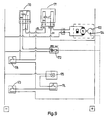
- Figure 9 shows a possible embodiment of the electrical system associated with the tilting device which has been explained with reference to Figure 8.
- reference numeral 170 denotes a first relay and 171 denotes a second relay.
- a pressure switch 172 which is in communication with the pressure port 104 of the pump 100.
- Figure 9 also shows a main switch 173, a switch 174 which is actuated in the locked position of the cab, a control lamp switch 175 and a start/stop switch 176.
- the pressure switch 172 is adjusted to a switching pressure which is higher than the normal working pressure of the hydraulic system while the cab is being tilted. However, the switching pressure is lower than the pressure which is reached if the piston rod 121 reaches one of its limit positions.
- the pump 100 should therefore be able to produce a pressure which is higher than the switching pressure, for example the switching pressure may be 350 bar. If the piston rod 121 reaches one of its limit positions, the pressure switch 175 is activated and the pump 100 is switched off. In fact, in this situation, it is possible to make do without the pressure-relief valve 103.
- the electrical circuit diagram prevents the pump 100 from inadvertently being switched on again if the switch 176 remains actuated while the piston rod 121 was already in one of its limit positions and the pressure switch 172 had already switched off the pump 100.
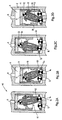
- FIGS 1a-d diagrammatically depict longitudinal sections through the hydraulic valve 1.
- the valve 1 comprises a housing 2 with a cylindrical bore 3 in the housing 2.
- the bore 3 has an imaginary axial axis 1 (cf. Fig. 1a) and at each of its axial ends is delimited by a base 4, 5 of the housing 2.
- the valve 1 also comprises a sliding body 6 which can slide in a reciprocating manner in the axial direction in the bore 3.
- the sliding body 6 is in this case more or less cup-shaped, with an annular wall 7 and a transverse wall 8.
- the external diameter of the annular wall 7 is such that the sliding body 6 fits in a sealing manner to bore 3 with a sliding fit. If appropriate, one or more sealing rings or the like may be provided around the sliding body 6.
- the sliding body 6 fits into the bore 7 in such a manner that an inlet chamber 9 and an outlet chamber 10 are defined in the bore 3.
- the sliding body 3 can slide between an at-rest position (Figs. 1a, 1c) and an actuated position (Figs. 1b, 1d).
- In the housing 2 there is an inlet passage 11 which, at an inlet opening 12, is connected to the inlet chamber 9.
- a first outlet passage 13 and a second outlet passage 14 are formed in the housing 2.
- the outlet passages 13, 14 are each connected to the outlet chamber 10 at an associated first and second outlet opening 15, 16, respectively.
- the openings 15, 16 are located adjacent to one another in the base 5 of the housing 2.
- a through-passage 17, which extends between the inlet chamber 9 and the outlet chamber 10, is provided centrally in the transverse wall 8 of the sliding body 6.
- the ball 20 can be displaced between a first position and a second position. In its first position (Fig. 1c), the ball 20 shuts off the first outlet opening 15, while the second outlet opening 16 is open. In its second position, the ball 20 shuts off the second outlet opening 16 and the first outlet opening 15 is open.
- a switching assembly 25 which on one side acts on the sliding body 6 and on the other side acts on the ball 20, is accommodated in the outlet chamber 10.
- the assembly 25 comprises a telescopic switching element having a first body 26 and a second body 27, which bodies 26, 27 are guided telescopically with respect to one another. Furthermore, there is a spring 28 which forces the first and second bodies 26, 27 apart.
- the first body 26 fits slideably into a receiving opening in the second body 27.
- the compression spring 28 is also located in this receiving opening.
- the ball 20 is arranged fixed to the second body 27.
- the telescopic switching assembly 25 can be elastically compressed under the influence of sliding of the sliding body 6 from the at-rest position towards the actuated position.
- the through-passage 17 in the sliding body 6 is such that a flow of hydraulic fluid from the inlet chamber 9 to the outlet chamber 10 causes the sliding body 6 to slide towards the actuated position.
- the assembly 25 restores the sliding body 6 towards the at-rest position when the hydraulic flow from the inlet chamber 9 towards the outlet chamber 10 ceases.
- the assembly 25 can adopt a first limit diagonal position (Fig. 1c) and a second limit diagonal position (Fig. 1a) with respect to the axial axis 1 of the valve 1.
- the assembly 25 When the sliding body 6 slides from the at-rest position towards the actuated position, the assembly 25, on account of hydraulic fluid flowing through the through-passage 17 in the sliding body 6, adopts the first limit diagonal position, and as a result holds the ball 20 in the first position. In this first position, the ball 20 bears in a sealing manner against the outlet opening 15 in the base 5. As a result, hydraulic fluid then flows from the inlet passage 9 towards the second outlet passage 14. In the event of the sliding body 6 sliding towards the at-rest position under the influence of the said assembly 25, which sliding motion occurs when the said flow of hydraulic fluid through the through-passage 17 in the sliding body 6 ceases, the assembly 25 tilts. If the telescopic assembly 25 was in the first limit diagonal position, the tilting is directed in the direction of the second limit diagonal position.
- the assembly 25 adopts the second limit diagonal position and thereby moves the ball 20 into its second position.
- the ball 20 bears against the outlet opening 16 in the base 5, so that hydraulic fluid flows from the inlet passage 11 towards the first outlet passage 13.
- the assembly 25 can engage on the sliding body 6 at diametrically opposite positions, in each case so as to form a tilting point 30, 31 for the telescopic assembly 25, in such a manner that when the sliding body 6 is being restored to the at-rest position, the assembly 25, which is in the first or second limit diagonal position, executes a tilting motion with respect to the corresponding tilting point 30, 31, in the direction of the second or first limit diagonal position, respectively.
- the switching element of the telescopic assembly 25 can engage, at diametrically opposite locations 30, 31, with the sliding body 6 so as to form a hook connection between the two components, in such a manner that in the event of the sliding body 6 being restored to the at-rest position, the assembly 25 which is in the first or second limit diagonal position tilts towards the other limit diagonal position and reaches an intermediate position (cf. Figures 1a, 1c).
- a second ball 32 is provided for shutting off the through-passage 17 in the sliding body 6 in the at-rest position of the sliding body 6.
- the second ball 32 is fixed to the first body 26 of the assembly 25, in such a manner that in the first and second limit diagonal positions the second ball 32 opens up the through-passage 17 and in each intermediate position of the telescopic assembly 25 shuts off the through-passage 17.
- a first and a second bypass passage 34, 35 the openings of which are connected to the outlet chamber 10 and respectively form a connection to the first and second outlet passages 13, 14 other than via the outlet openings 15, 16 thereof, are also provided in the housing 2.
- the sliding body 6 shuts off the openings of the bypass passages 34, 35, and in a position other than the actuated position the openings of the bypass passages are opened up.
- a flexible sealing ring 36 is arranged on the bottom of the annular wall 7. The function of the bypass passages 34, 35 is clearly apparent if the transition from the position shown in Figure 1b to Figure 1c is considered.
- bypass passages 34, 35 are connected to the outlet chamber 10. This is considerably earlier than the time at which the initially closed opening 15, 16 of the passage 13 or 14 is opened up. If the passages 13, 14 and the bypass passages 34, 35 are in communication with an unpressurized reservoir, the bypass passages 34, 35 therefore ensure that the pressure in the outlet chamber 10 drops quickly.
- the second body 27 is provided with an outwardly projecting circumferential edge 37 with an undercut.
- the sliding body 6, on the inside of the annular wall 7, is provided, at diametrically opposite positions, with tilting-point members 38, 39 having a corresponding undercut, in such a manner that the telescopic assembly 25, by engagement of the circumferential edge 37 with one of the tilting-point members 38, 39, forms a tilting point 30, 31 as well as a connection to the sliding body 6.
- the telescopic assembly 25 tilts about this corresponding tilting point towards an intermediate position and is held in this intermediate position.
- the circumferential edge 37 comes free of the corresponding tilting-point member, and the telescopic assembly 25 adopts its other limit diagonal position.
- FIGS 2a-d show another embodiment of the valve according to the invention; components which correspond to the valve 1 shown in Figures 1a-d are provided with the same reference numerals.
- the valve 40 is provided with a sliding body 6, which can slide inside a bore in the housing 2 between an at-rest position and an actuated position.
- the valve 40 has a telescopic assembly 41 which to a considerable degree corresponds to the assembly 25 of the valve 1.
- Figure 6 clearly shows the sliding body 6 of the valve 40 as well as the telescopic assembly 41.
- the only difference from the assembly 25 is that the ball 20 is absent in the assembly 41, whereas in the assembly 25 this ball is integral with the body 27.
- the end of the body 42 forms a recess, by means of which the assembly 41 can engage on a ball, which does not belong to the telescopic assembly 41, of the first shut-off member 50, which is yet to be described.
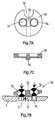
- the shut-off member 50 will be explained in more detail, partly with reference to Figures 7a-c.
- the shut-off member 50 is a separate component.
- the shut-off member 50 can be tilted with respect to the base 5 of the housing 2 about a tilting point 51 located between the openings of the outlet passages 13, 14 in the base 5.
- the shut-off member 50 comprises a first ball 53 and a second ball 54, which are accommodated in a common carrier 55, which carrier 55, between the balls 53, 54, is provided with a tilting projection 56, which at the tilting point 51 is tiltably supported on the base 5 of the housing 2.
- the balls 53, 54 are made from metal and the carrier 55 is made from plastic.
- the carrier 55 is provided with a positioning recess 57, into which a part of the housing 2 (not shown) fits, so that the carrier 55 can tilt but cannot rotate with respect to the housing 2.
- the balls 53, 54 on one side each form the shut-off surface for an outlet opening 15, 16 and on the other side also form the engagement formation for the telescopic assembly.
- These engagement formations are located on either side of the abovementioned tilting point 51 and are formed by those parts of the surface of the balls 53, 54 which face away from the base 5. In the first limit diagonal position, the assembly 40 engages on the ball 53 and presses this ball 53 onto the outlet opening 15, so that the outlet passage 13 is shut off.
- the ball 54 In this first tilted position of the shut-off member 50, the ball 54 is located at a distance from the outlet opening 16 and the outlet passage 14 is open. In the second limit diagonal position, the assembly 41 engages on the ball 54 and the outlet passage 14 is closed, while outlet passage 13 is held open.
- the telescopic assembly 41 is tilted in the same way as described with reference to Figures 1a-d and will therefore not be explained again.
- the ball 32 which is integral with body 26, shuts off the through-passage 17 in the sliding body 6.
- the valve 60 in Figures 3a-d has a structure which deviates slightly from the valves 1 and 40 described above.
- the housing 61 is provided with an inlet passage 11 and with outlet passages 62, 63 which are connected to a bore in the housing 61.
- a substantially cylindrical sleeve 64 is secured in the housing 61, for example with a clamp fit. The sleeve 64 extends over part of the axial length of the bore.
- Sliding body 73 fits in an axially slidable manner into the sleeve 64 and is provided with through-passage 17 between the inlet chamber 9 and the outlet chamber 10.
- a separate ring 66 which in this valve 60 serves as a first shut-off member for the outlet passages 62, 63.
- the ring 66 has a smaller external diameter than the bore in the housing 61 and can therefore move inside the bore with a certain play.
- the ring 66 is provided, on the side facing the base 5, with openings 67 through which fluid can pass, as will be explained below.
- the sleeve 64 is provided, on its side facing the moveable ring 66, with diametrically opposite engagement formations 68, 69 for the telescopic assembly 70.
- the engagement formations 68, 69 lie on the same axial line as the openings of the outlet passages 63, 64.
- the engagement formations 68, 69 project inwardly with respect to the annular wall of the sleeve 64 and can form a stop for the sliding body 73 in the actuated position thereof.
- the telescopic assembly 70 is substantially identical to the above-described assembly 25, but is now positioned upside-down. In this case, the first body 71 is now provided with a circumferential edge 72 which can be brought into engagement with one of the engagement formations 68, 69.
- the assembly 70 is in engagement with formation 69 and is therefore being held in an intermediate position.
- the assembly 70 presses the ring 66 onto the circumferential wall of the bore at the location of the opening of outlet passage 62, which is as a result shut off.
- the assembly 70 is in its other intermediate position, in which the assembly 70 is in engagement with the formation 68, which is stationary with respect to the housing 61.
- the assembly 70 is in its other limit diagonal position, in which the assembly 70 presses the ring 66 onto the circumferential wall of the bore at the location of the opening of the outlet passage 63, so that this opening is shut off.
- the ball 32 serves as a guide member and slides along the base of the housing 61.
- the ball 20, which in this case slides along the sliding member 73, has the same function. In the intermediate position of the assembly 70, there is no sealing of the through-passage 17 in the sliding body 73, as is the case in the valves which have been discussed above.
- the valve 80 shown in Figures 4a-d corresponds to a considerable degree to the valve 1 shown in Figures 1a-d. For this reason, corresponding components are provided with the same reference numerals and reference is made to the earlier explanation for a description of the way in which they operate.
- the ball 20 is in this case once again integral with the body 27 of the telescopic assembly 25.
- a first difference is that the ball 32, in the intermediate positions of the telescopic assembly 25, does not seal the through-passage 17 in the sliding body 6, as is the case in the valve 1, but rather leaves it open. Therefore, the ball 32 does not perform a sealing function, but rather a guiding function for the assembly 25, guiding it along the transverse wall 8 of the sliding body 6.
- a particular feature of the valve 80 is its design in the region of the connection of the outlet passages 13, 14 to the outlet chamber 10.
- a flexible disc 81 which bears against the base 5, is arranged on the base 5 of the housing 2. At its circumferential edge, the disc 81 is clamped into the housing 2. Openings are arranged in the disc 81 at the position of each of the outlet passages 13, 14.
- a sleeve 83, 84 in which there is a ball 85, 86 is arranged in these openings in such a manner that the balls 85, 86 act as non-return valves which close in the direction of the outlet chamber 10.
- Those ends of the sleeves 83, 84 which are remote from the base 5 in each case form a seat for the ball 20.
- the disc 81 In the at-rest position of the sliding body 6, i.e. when no pressurized hydraulic fluid is being supplied to the inlet passage 11, it may be desirable for an excessively high pressure not to remain or form in one of the outlet passages 13, 14.
- the non-return valves 85, 86 close off these passages 13, 14.
- the disc 81 adopts a convex position, so that in the region between the outlet openings, formed in the base 5, of the outlet passages 13, 14 and the underside of the disc 81 a connection is formed, along which this excess pressure can escape to the other outlet passage.
- the disc 81 forms an elastic pressure-relief valve between the outlet passages 13, 14, which valve is then actuated by the assembly 25 in such a manner that -the pressure relief connection is closed when the sliding body 6 is in the actuated position.
- the valve 200 shown in Figure 5 is a variant on the valve 60 shown in Figure 3. Since the operation of the valve according to the invention has already been explained a number of times, in this case it will be sufficient just to describe Figure 5.
- the housing 201 is provided with an inlet passage 202 and with outlet passages 203, 204, which are connected to a bore in the housing 201.
- a substantially cylindrical sleeve 205 is secured in the housing 201, for example with a clamping fit.
- the sleeve 205 extends over part of the axial length of the bore.
- Sliding body 206 fits in an axially slideable manner into the bore and is provided with through-passage 207 between the inlet chamber 208 and the outlet chamber 209.
- annular body 211 having an annular wall 211a and a base 211b, which in this valve 200 serves as a shut-off member for the outlet passages 203, 204.
- the annular body 211 has a smaller external diameter than the bore in the housing 201 and can therefore move inside the bore with a certain play.
- the annular body 211 is provided, on the side facing the base 210, with openings which are delimited by projections 212 and through which fluid can pass, as will be explained below.
- the sleeve 205 On its side facing the moveable ring 211, the sleeve 205 is provided with diametrically opposite engagement formations 215, 216 for a rigid switching element 220.
- the engagement formations 215, 216 lie on the same axial line as the openings of the outlet passages 203, 204.
- the engagement formations 215, 216 project inwards with respect to the annular wall 211a, so that the top edge of the annular wall 211a is guided in such a manner that it can slide around them in the axial direction with radial play.
- the rigid switching element 220 is provided with a circumferential edge 221, which can be brought into engagement with one of the engagement formations 215, 216. It can be seen from Figure 5 that the switching element 220 is in engagement with formation 216. In this case, the sliding body 206 is in its actuated position, because there is a flow of fluid through the through-passage 207.
- the switching element 220 presses the annular body 211 onto the circumferential wall of the bore at the location of the opening of the outlet passage 204, which is shut off as a result.
- the ends 220a, 220b of the switching element 220 are of pointed design and during operation slide along an associated wall of the sliding body 206 and the annular body 211.
- a spring 230 is positioned between the base 210 and the annular body 211 and presses the said annular body 211 in the direction of the switching element 220.
- the annular body 211 can therefore slide in the axial direction with respect to the housing 201.
- a bottom part 233 has a smaller diameter than a top part 234.
- openings 232 for the flow of fluid through the valve 200 are also arranged in the base wall 211b.
- the annular body 211 in particular the annular wall 211a, to be flexible.
Landscapes
- Engineering & Computer Science (AREA)
- Mechanical Engineering (AREA)
- General Engineering & Computer Science (AREA)
- Chemical & Material Sciences (AREA)
- Combustion & Propulsion (AREA)
- Transportation (AREA)
- Physics & Mathematics (AREA)
- Fluid Mechanics (AREA)
- Multiple-Way Valves (AREA)
- Fluid-Pressure Circuits (AREA)
- Forklifts And Lifting Vehicles (AREA)
- Servomotors (AREA)
Claims (29)
- Hydraulische Kippeinrichtung zum Kippen der Fahrerkabine eines Fahrzeugs zwischen einer Fahrposition, in der das Fahrzeug normal gefahren werden kann, und einer gekippten Position, in der beispielsweise eine Wartung an einem unterhalb der Kabine angeordneten Fahrzeugmotor ausgeführt werden kann, umfassend:- einen Kippzylinder (120) mit einem ersten und einem zweiten Anschluss (122, 123),- einen Speicher (102) für Hydraulikfluid,- eine Pumpe (100) mit einer einfachen Pumprichtung, wobei die Pumpe einen Sauganschluss (101), der sich mit dem Speicher in Wirkverbindung befindet, und einen Abgabeanschluss (104) zum Abgeben unter Druck befindlichen Hydraulikfluids aufweist,- ein Ventil (1; 40; 60; 80; 200) mit einem Einlassdurchgang (11; 202), der mit dem Abgabeanschluss der Pumpe und einem ersten und einem zweiten Auslassdurchgang (13, 14) verbunden ist, wobei das Ventil ein betätigbares Unterbrecherteil (20; 50; 66; 211) aufweist derart, dass in dessen erster Stellung der Abgabeanschluss über den ersten Auslassdurchgang mit dem ersten Anschluss des Kippzylinders und in dessen zweiter Stellung der Abgabeanschluss über den zweiten Auslassdurchgang mit dem zweiten Anschluss des Kippzylinders verbunden ist,dadurch gekennzeichnet, dass das Ventil weiterhin hydraulische Betätigungsmittel (6,25; 41; 70; 206, 230) zum Betätigen des Unterbrecherteils umfasst, die so ausgestaltet sind, dass in Folge der Zufuhr von Hydraulikfluid durch die Pumpe an den Einlassdurchgang das Unterbrecherteil in die erste Stellung oder in die zweite Stellung bewegt wird und dass in Folge des dann erfolgenden Unterbrechens oder Verminderns dieser Zufuhr und der neuerlichen Wiederaufnahme derselben das Unterbrecherteil in die zweite Stellung bzw. die erste Stellung bewegt wird.
- Hydraulische Kippeinrichtung nach Anspruch 1, bei der die hydraulischen Betätigungsmittel einen Körper (6; 206), der zwischen einer Ruhestellung und einer Betriebsstellung verlagerbar und in einem Gehäuse (1) untergebracht ist, vorzugsweise einen Gleitkörper (6; 206), der innerhalb einer zugeordneten Bohrung (3) verschiebbar ist und sich von der Ruhestellung in Folge der Zufuhr des Hydraulikfluids an den Einlassdurchgang in die Betriebsstellung bewegt, sowie eine zugeordnete Rückstellanordnung (25; 41; 70; 230) zum Zurückführen des Körpers umfassen.
- Hydraulische Kippeinrichtung nach Anspruch 2, bei der der Körper (6; 206) mit einem durchgehenden Durchgang (17; 207) derart versehen ist, dass der Hydraulikfluid-Strom von der Pumpe durch den Einlassdurchgang (11; 202) und durch den durchgehenden Durchgang an einen Auslassdurchgang des Ventils den Körper (6; 206) zur Betriebsstellung hin entgegen der Wirkung der Rückstellanordnung (25; 41; 70; 230) bewegt.
- Hydraulische Kippeinrichtung nach Anspruch 2 oder 3, bei der ein Schaltelement (26, 27) zwischen dem Körper (6; 206) und dem Unterbrecherteil (20; 50; 66; 211) derart angeordnet ist, dass während einer ersten Verlagerung des Körpers zur Betriebsstellung hin das Unterbrecherteil in die erste oder zweite Stellung bewegt wird und dass in Folge des Unterbrechens oder Reduzierens dieser Zufuhr und der neuerlichen Wiederaufnahme derselben das Unterbrecherteil in die zweite bzw. die erste Stellung bewegt wird.
- Hydraulische Kippeinrichtung nach einem oder mehreren der vorhergehenden Ansprüche, bei der das Ventil umfasst:- ein Gehäuse (1; 201),- eine Bohrung (3) in dem Gehäuse, die eine imaginäre axiale Hauptlinie aufweist und an jedem ihrer axialen Enden durch eine Basis des Gehäuses begrenzt ist,- einen Gleitkörper (6; 206), der hin- und herbewegt in der Axialrichtung in der Bohrung gleiten kann und eine Einlasskammer (9; 208) sowie eine Auslasskammer (10; 210) in der Bohrung bestimmt, wobei der Gleitkörper zwischen einer Ruhestellung und einer Betriebsstellung gleiten kann,- einen Einlassdurchgang (11; 202) in dem Gehäuse, der an einer Einlassöffnung mit der Einlasskammer verbunden ist,- einen ersten Auslassdurchgang (13; 203; 62), der in dem Gehäuse ausgebildet ist, und einen zweiten Auslassdurchgang (14; 204; 63), der in dem Gehäuse ausgebildet ist, wobei die Auslassdurchgänge jeweils mit der Auslasskammer (10; 210) an einer zugeordneten ersten bzw. zweiten Auslassöffnung (15, 16) verbunden sind,- einen durchgehenden Durchgang (17; 207), der sich zwischen Einlasskammer sowie Auslasskammer erstreckt und in dem Gleitkörper vorgesehen ist,- ein in der Auslasskammer untergebrachtes, zu betätigendes Unterbrecherteil (20; 50; 66; 211), das in seiner ersten Stellung die erste Auslassöffnung abschließt sowie die zweite Auslassöffnung freigibt und in seiner zweiten Stellung die erste Auslassöffnung freigibt sowie die zweite Auslassöffnung abschließt,- eine ebenfalls in der Auslasskammer untergebrachte Schaltanordnung (25; 41; 70; 220, 230) zum Betätigen des Unterbrecherteils,- wobei die Schaltanordnung auf einer Seite auf den Gleitkörper und auf der anderen Seite auf das Unterbrecherteil einwirkt,- wobei der durchgehende Durchgang in dem Gleitkörper so vorgesehen ist, dass ein Strom von Hydraulikfluid von der Einlasskammer zur Auslasskammer den Gleitkörper zur Betriebsstellung hin schiebt, und wobei der Gleitkörper in die Ruhestellung zurückkehrt, wenn dieser Strom endet,- wobei die Schaltanordnung in dem Falle, dass der Gleitkörper in Folge des Fließens von Hydraulikfluid durch den durchgehenden Durchgang in dem Gleitkörper aus der Ruhestellung zur Betriebsstellung hin gleitet, das erste Unterbrecherteil in der ersten Stellung hält, so dass Hydraulikfluid von dem Einlassdurchgang zum zweiten Auslassdurchgang hin fließt,- und wobei die Schaltanordnung, wenn diese Hydraulikströmung endet und dann wieder aufgenommen wird, so dass der Gleitkörper zurück zur Betriebstellung hin gleitet, das erste Unterbrecherteil in dessen zweite Stellung bewegt, so dass Hydraulikfluid von dem Einlassdurchgang zum ersten Auslassdurchgang fließt.
- Hydraulische Kippeinrichtung nach Anspruch 5, bei der die Schaltanordnung (25; 41; 70; 220, 230) ein Schaltelement (26, 27; 71; 220) umfasst, das in der Auslasskammer zwischen dem Gleitkörper und dem Unterbrecherteil angeordnet ist, und bei der die Schaltanordnung weiter ein Federelement (28; 230) umfasst, das elastisch unter dem Einfluss des Gleitens des Gleitkörpers aus der Ruhestellung zur Betriebsstellung hin komprimiert werden kann, wobei die Schaltanordnung den Gleitkörper in die Ruhestellung zurückstellt, wenn der Hydraulikstrom von der Einlasskammer zur Auslasskammer hin endet, bei der das Schaltelement eine erste diagonale Grenzstellung und eine zweite diagonale Grenzstellung im Hinblick auf die axiale Hauptlinie des Ventils einnehmen kann,
bei der das Schaltelement, wenn der Gleitkörper in Folge des Strömens von Hydraulikfluid durch den durchgehenden Durchgang in dem Gleitkörper aus der Ruhestellung zur Betriebsstellung hin gleitet, die erste diagonale Grenzstellung einnimmt und dadurch das Unterbrecherteil in der ersten Stellung hält, so dass Hydraulikfluid von dem Einlassdurchgang zum zweiten Auslassdurchgang hin fließt,
und bei der das Schaltelement (26, 27), wenn der Gleitkörper unter Einfluss des Schaltelements zur Ruhestellung hin gleitet, wenn das Fließen des Hydraulikfluids durch den durchgehenden Durchgang in dem Gleitkörper endet, in Richtung der zweiten diagonalen Grenzstellung kippt,
und bei der das Schaltelement, wenn nachfolgend der Gleitkörper in Folge der Wiederaufnahme des Fließens von Hydraulikfluid durch den durchgehenden Durchgang in den Gleitkörper zur Betriebsstellung hin gleitet, die zweite diagonale Grenzstellung einnimmt und dadurch das Unterbrecherteil in seine zweite Stellung bewegt, so dass Hydraulikfluid von dem Einlassdurchgang zum ersten Auslassdurchgang hin fließt. - Hydraulische Kippeinrichtung nach Anspruch 5 oder 6, bei der die Schaltanordnung ein teleskopisches Schaltelement umfasst, das einen ersten Körper (26) und einen zweiten Körper (27) umfasst, die beide teleskopisch im Verhältnis zueinander geführt sind, und bei der das Federelement (28) der Schaltanordnung so angeordnet ist, dass das Federelement die ersten und zweiten Körper auseinander drückt, wobei der erste Körper auf den Gleitkörper und der zweite Körper auf das Unterbrecherteil einwirkt.
- Hydraulische Kippeinrichtung nach Anspruch 5 oder 6, bei der die Schaltanordnung ein starres Schaltelement (220) mit einem ersten und einem zweiten Ende umfasst, die jeweils auf den Gleitkörper (206) und das Unterbrecherteil (211) einwirken, und bei der das Federelement (230) zwischen dem Gehäuse und dem Unterbrecherteil angeordnet ist.
- Hydraulische Kippeinrichtung nach einem oder mehreren der vorhergehenden Ansprüche 5 - 8, bei der das Schaltelement (26, 27; 220) in diametral entgegengesetzten Stellungen zum Einwirken auf das Gehäuse oder den Gleitkörper gelangen kann, um in jedem Falle einen Kipppunkt.(30, 31) für das Schaltelement derart zu bilden, dass, wenn der Gleitkörper in die Ruhestellung zurückgeführt wird, das Schaltelement, das sich in der ersten oder zweiten diagonalen Grenzstellung befindet, in Richtung der zweiten bzw. ersten diagonalen Grenzstellung eine Kippbewegung in Bezug auf den entsprechenden Kipppunkt ausübt.
- Hydraulische Kippeinrichtung nach Anspruch 9, bei der das Schaltelement (26, 27; 220) in diametral entgegengesetzten Stellungen in Eingriff mit dem Gehäuse oder dem Gleitkörper gelangen kann, um eine Hakenverbindung (31, 38, 39) zwischen den beiden Komponenten in der Weise zu bilden, dass, wenn der Gleitkörper in die Ruhestellung zurückgestellt wird, das Schaltelement, das sich in der ersten oder zweiten diagonalen Grenzstellung befindet, in Richtung der anderen diagonalen Grenzstellung kippt und eine Zwischenstellung erreicht.
- Hydraulische Kippeinrichtung nach einem oder mehreren der vorhergehenden Ansprüche 5 - 10, bei der ein zweites Unterbrecherteil (32) zum Unterbrechen des durchgehenden Durchgangs (17) in dem Gleitkörper (6) in der Ruhestellung des Gleitkörpers vorgesehen ist.
- Hydraulische Kippeinrichtung nach Ansprüchen 6 und 11, bei der das zweite Unterbrecherteil (32) durch das Schaltelement (26, 27) in der Weise betätigt werden kann, dass in den ersten und zweiten diagonalen Grenzstellungen das zweite Unterbrecherteil den durchgehenden Durchgang freigibt und in irgendeiner Zwischenposition des Schaltelements den durchgehenden Durchgang abschließt, und bei der das zweite Unterbrecherteil vorzugsweise integral mit dem Schaltelement ausgebildet ist, wobei beispielsweise das zweite Unterbrecherteil eine Einzelkugel (32) ist.
- Hydraulische Kippeinrichtung nach Anspruch 6, bei der das erste Unterbrecherteil (20) in das Schaltelement (26, 27) integriert ist sowie die Auslassöffnungen der ersten und zweiten Auslassdurchgänge (13, 14) in der Basis des Gehäuses derart angeordnet sind, dass in der ersten diagonalen Grenzstellung des Schaltelements das erste Unterbrecherteil dichtend gegen die Auslassöffnung des ersten Auslassdurchgangs und in der zweiten diagonalen Grenzstellung gegen die Auslassöffnung des zweiten Auslassdurchgangs drückt, und bei der das erste Unterbrecherteil vorzugsweise eine Einzelkugel ist.
- Hydraulische Kippeinrichtung nach einem oder mehreren der vorhergehenden Ansprüche 5 - 13, bei der ein erster und ein zweiter Umgehungsdurchgang (34, 35), von denen eine Öffnung mit der Auslasskammer (10) verbunden ist, eine Verbindung zwischen den ersten und zweiten Auslassdurchgängen außer über die Auslassöffnungen (15, 16) derselben bildend, in dem Gehäuse (2) vorgesehen sind, und bei der der Gleitkörper (6) in der Betriebsstellung die Öffnungen der Umgehungsdurchgänge abschließt und in einer Stellung, die von der Betriebsstellung abweicht, die Öffnungen der Umgehungsdurchgänge freigibt.
- Hydraulische Kippeinrichtung nach Anspruch 6, bei der das erste Unterbrecherteil (50) von dem Schaltelement (41) getrennt ist und in Bezug auf die Basis des Gehäuses um einen Kipppunkt gekippt werden kann, der sich zwischen den Öffnungen der Auslassdurchgänge (13, 14) in der Basis befindet, wobei das erste Unterbrecherteil auf jeder Seite des Kipppunktes mit einer Unterbrecherfläche (53, 54) für die entsprechende Öffnung derart versehen ist, dass in der ersten gekippten Stellung die erste Auslassöffnung und in der zweiten gekippten Stellung die zweite Auslassöffnung abgeschlossen ist, und bei der das erste Unterbrecherteil vorzugsweise mit einer ersten und zweiten Eingriffsausbildung (53, 54) für das Schaltelement versehen ist, wobei diese Eingriffsausbildungen sich derart im Abstand zueinander auf jeder Seite des Kipppunktes des ersten Unterbrecherteils befinden, dass das Schaltelement (41) in der ersten diagonalen Grenzstellung an der ersten und in der zweiten diagonalen Grenzstellung an der zweiten Eingriffsausbildung ein- bzw. angreift.
- Hydraulische Kippeinrichtung nach Anspruch 15, bei der das erste Unterbrecherteil (50) eine erste und eine zweite Kugel (53, 54) umfasst, die in einem gemeinsamen Träger untergebracht sind, wobei der Träger zwischen den Kugeln kippbar an der Basis des Gehäuses abgestützt ist, und bei der vorzugsweise die ersten und zweiten Kugeln (53, 54) jeweils einerseits die Unterbrecherfläche für eine Auslassöffnung und andererseits ebenfalls die Eingriffsausbildung für das Schaltelement (41) bilden.
- Hydraulische Kippeinrichtung nach Anspruch 6, bei der die Auslassöffnungen (62, 63; 203; 204) in der Umfangswandung der Bohrung in dem Gehäuse an diametral entgegengesetzten Stellen ausgebildet sind und bei der das erste Unterbrecherteil ein ringförmiger Körper (66; 211) ist, der mit radialem Spiel in die Bohrung passt, sich an der Stelle der Auslassöffnungen in der Bohrung befindet und in seiner ersten Stellung die erste Auslassöffnung und in seiner zweiten Stellung die zweite Auslassöffnung dichtend abdeckt, wobei das Schaltelement (70; 220) ausgebildet ist, um auf den ringförmigen Körper einzuwirken.
- Hydraulische Kippeinrichtung nach Anspruch 17, bei der das Schaltelement ein teleskopisches Schaltelement (70) ist, das gleitfähig gegen die Basis des Gehäuses in der Nähe des ringförmigen Körpers abgestützt ist.
- Hydraulische Kippeinrichtung nach Anspruch 17, bei der das Schaltelement ein starres Schaltelement (220) ist, das gegen den ringförmigen Körper (211), vorzugsweise gegen eine Basiswandung (211 b), gestützt ist, die in dem ringförmigen Körper vorgesehen ist, und bei der das Federelement (230) zwischen dem Gehäuse und dem ringförmigen Körper angeordnet ist.
- Hydraulische Kippeinrichtung nach Anspruch 18 oder 19, bei der ein oder mehrere durchgehende Durchgänge (232) für hindurchzutretende Hydraulikflüssigkeit in dem ringförmigen Körper (66) vorgesehen sind.
- Hydraulische Kippeinrichtung nach einem oder mehreren der vorhergehenden Ansprüche, bei der die Auslassöffnungen des Ventils jeweils mit einem Rückschlagventil (85, 86) versehen sind, das in Richtung der Auslasskammer schließt.
- Hydraulische Kippeinrichtung gemäß einem oder mehreren der vorhergehenden Ansprüche, bei der eine Umgehungsverbindung mit einem elastischen Unterbrecherteil (81) zwischen den Auslassdurchgängen (13, 14) vorgesehen ist, wobei das Unterbrecherteil im Falle überschüssigen Drucks in einem der Auslassdurchgänge in Bezug auf den anderen Auslassdurchgang die Umgehungsverbindung öffnet, und bei der das Schaltelement nach Anspruch 6 vorzugsweise das elastische Unterbrecherteil (81) derart betätigt, dass in jeder diagonalen Grenzstellung des Schaltelements die Umgehungsverbindung durch das Unterbrecherteil abgeschlossen ist.
- Hydraulische Kippeinrichtung nach Ansprüchen 21 und 22, bei der das elastische Unterbrecherteil ein Platten- oder Scheibenkörper (81) ist, der gegen die Basis des Gehäuses drückt, wobei die Rückschlagventile (85, 86) in dem Platten- oder Scheibenkörper untergebracht sind, wobei dieser Platten- oder Scheibenkörper an seinem Umfangsrand an dem Gehäuse befestigt ist und sich im Bereich zwischen den Öffnungen der Auslassdurchgänge (13, 14) in der Basis des Gehäuses elastisch von dieser Basis unter dem Einfluss eines überschüssigen Drucks in einem Auslassdurchgang wenigstens in der Ruhestellung des Gleitkörpers des Ventils wegbiegen kann.
- Hydraulische Kippeinrichtung nach einem oder mehreren der vorhergehenden Ansprüche 2 - 23, bei der der Gleitkörper (6) ein ringförmiger Körper mit einer Querwandung (8) ist, die mit einem zentralen durchgehenden Durchgang (17; 207) versehen ist.
- Hydraulische Kippeinrichtung nach Anspruch 6, bei der das Schaltelement (26, 27; 220) mit einem nach außen vorspringenden Umfangsrand (37; 221) mit einem Hinterschnitt versehen ist und bei der das Gehäuse oder der Gleitkörper (6) an diametral entgegengesetzten Positionen mit Kipppunktteilen (38, 39; 215, 216) mit einem entsprechenden Hinterschnitt derart versehen ist, dass das Schaltelement in Folge des mit einem Kipppunktteil in Eingriff tretenden Umfangsrands einen Kipppunkt und eine Verbindung zu dem Gehäuse oder dem Gleitkörper bildet, so dass dann, wenn der Gleitkörper von der Betriebsstellung zur Ruhestellung hin gleitet, das Schaltelement um den entsprechenden Kipppunkt zu einer Zwischenposition hin kippt und in dieser Zwischenposition gehalten wird, wobei der Umfangsrand von dem Kipppunktteil freikommt und das Schaltelement seine andere diagonale Grenzstellung einnimmt, wenn der Gleitkörper nachfolgend zur Betriebsstellung hin gleitet.
- Hydraulische Kippeinrichtung nach Anspruch 25, bei der das Kipppunktteil (38, 39) an dem Gleitkörper (6) und der Umfangsrand (37) an dem zweiten Körper (27) des Schaltelements vorgesehen sind.
- Hydraulische Kippeinrichtung nach Anspruch 26, bei der das Kipppunktteil (215, 216) an dem Gehäuse (205) und der Umfangsrand (211) an dem ersten Körper des Schaltelements vorgesehen sind.
- Hydraulische Kippeinrichtung nach Anspruch 26, bei der die Kipppunktteile durch Schaffen eines inneren Randes in dem Gleitkörper und anschließendes Ausbilden zweier Schlitzrezesse auf der Höhe dieses Randes derart gebildet sind, dass zwei diametral entgegengesetzte Kipppunktteile verbleiben.
- Hydraulische Kippeinrichtung nach Anspruch 21, bei der die Rückschlagventile in einem elastisch verformbaren Körper untergebracht sind, der mindestens in einem Verbindungsbereich zwischen den Auslassdurchgängen dichtend gegen die Basis des Gehäuses drücken kann.
Applications Claiming Priority (3)
| Application Number | Priority Date | Filing Date | Title |
|---|---|---|---|
| NL1022163 | 2002-12-13 | ||
| NL1022163A NL1022163C2 (nl) | 2002-12-13 | 2002-12-13 | Hydraulische klep. |
| PCT/NL2003/000859 WO2004055388A1 (en) | 2002-12-13 | 2003-12-04 | Hydraulic tilting device for tilting the cab of a vehicle |
Publications (2)
| Publication Number | Publication Date |
|---|---|
| EP1570183A1 EP1570183A1 (de) | 2005-09-07 |
| EP1570183B1 true EP1570183B1 (de) | 2007-07-04 |
Family
ID=32589148
Family Applications (1)
| Application Number | Title | Priority Date | Filing Date |
|---|---|---|---|
| EP03779052A Expired - Lifetime EP1570183B1 (de) | 2002-12-13 | 2003-12-04 | Hydraulische kippvorrichtung zum kippen des fahrergehäuses eines fahrzeuges |
Country Status (10)
| Country | Link |
|---|---|
| US (1) | US7252029B2 (de) |
| EP (1) | EP1570183B1 (de) |
| JP (1) | JP2006509983A (de) |
| KR (1) | KR20050085637A (de) |
| CN (1) | CN1308598C (de) |
| AT (1) | ATE366371T1 (de) |
| AU (1) | AU2003289677A1 (de) |
| DE (1) | DE60314773T2 (de) |
| NL (1) | NL1022163C2 (de) |
| WO (1) | WO2004055388A1 (de) |
Families Citing this family (4)
| Publication number | Priority date | Publication date | Assignee | Title |
|---|---|---|---|---|
| NL1029030C2 (nl) * | 2005-05-12 | 2006-11-14 | Actuant Corp | Hydraulisch systeem. |
| NL2001308C2 (nl) * | 2008-02-21 | 2009-08-24 | Actuant Corp | Voertuigcabinekantelinrichting met telescopische kantelcilinder. |
| CN106337846B (zh) * | 2016-10-12 | 2018-08-17 | 中南大学 | 可实现顺序夹桩的压桩机夹桩液压系统和控制方法及夹桩顺序控制阀 |
| CN110410376B (zh) * | 2019-06-25 | 2021-02-12 | 浙江科力车辆控制系统有限公司 | 集成式电控换向油泵 |
Family Cites Families (7)
| Publication number | Priority date | Publication date | Assignee | Title |
|---|---|---|---|---|
| US3985194A (en) | 1974-08-30 | 1976-10-12 | Applied Power Inc. | Tilt cab power stream and valve control therefor |
| US4029119A (en) * | 1975-04-30 | 1977-06-14 | Hal Klieves | Valve and valve system |
| US4561343A (en) * | 1981-08-27 | 1985-12-31 | Jobst Institute, Inc. | Sequencing valve mechanism |
| US5022426A (en) * | 1990-07-05 | 1991-06-11 | Fischer Andrew P | Pressure operated sequencing valve |
| FR2743047B1 (fr) * | 1995-12-27 | 1998-02-20 | Renault Vehicules Ind | Dispositif de basculement d'une cabine supportee par un chassis |
| DE19947323A1 (de) * | 1999-10-01 | 2001-04-05 | Bsh Bosch Siemens Hausgeraete | Haushalt-Geschirrspülmaschine |
| US6505684B2 (en) * | 2000-10-20 | 2003-01-14 | Schlumberger Technology Corporation | Hydraulic actuator |
-
2002
- 2002-12-13 NL NL1022163A patent/NL1022163C2/nl not_active IP Right Cessation
-
2003
- 2003-12-04 KR KR1020057010837A patent/KR20050085637A/ko not_active Ceased
- 2003-12-04 AU AU2003289677A patent/AU2003289677A1/en not_active Abandoned
- 2003-12-04 DE DE2003614773 patent/DE60314773T2/de not_active Expired - Fee Related
- 2003-12-04 EP EP03779052A patent/EP1570183B1/de not_active Expired - Lifetime
- 2003-12-04 US US10/538,340 patent/US7252029B2/en not_active Expired - Fee Related
- 2003-12-04 CN CNB2003801016929A patent/CN1308598C/zh not_active Expired - Fee Related
- 2003-12-04 WO PCT/NL2003/000859 patent/WO2004055388A1/en not_active Ceased
- 2003-12-04 AT AT03779052T patent/ATE366371T1/de not_active IP Right Cessation
- 2003-12-04 JP JP2004560708A patent/JP2006509983A/ja active Pending
Non-Patent Citations (1)
| Title |
|---|
| None * |
Also Published As
| Publication number | Publication date |
|---|---|
| WO2004055388A1 (en) | 2004-07-01 |
| DE60314773T2 (de) | 2008-05-15 |
| AU2003289677A1 (en) | 2004-07-09 |
| US7252029B2 (en) | 2007-08-07 |
| DE60314773D1 (de) | 2007-08-16 |
| CN1705828A (zh) | 2005-12-07 |
| ATE366371T1 (de) | 2007-07-15 |
| NL1022163C2 (nl) | 2004-07-09 |
| EP1570183A1 (de) | 2005-09-07 |
| KR20050085637A (ko) | 2005-08-29 |
| US20060117943A1 (en) | 2006-06-08 |
| CN1308598C (zh) | 2007-04-04 |
| JP2006509983A (ja) | 2006-03-23 |
Similar Documents
| Publication | Publication Date | Title |
|---|---|---|
| CN110030182B (zh) | 用于输送压力介质回路中的压力介质的活塞泵 | |
| CN109416060B (zh) | 缸驱动装置 | |
| US7252029B2 (en) | Hydraulic tilting device for tilting the cab of a vehicle | |
| WO2009097117A1 (en) | Variable volume reservoir | |
| EP1875083B1 (de) | Werkzeug mit hydraulikventilsystem | |
| US5325763A (en) | Internal check valve | |
| JP4108591B2 (ja) | 揺戻り防止弁装置、ならびにこれを備える制御ユニットおよび流体圧設備 | |
| JP2004514847A (ja) | 傾動装置及びこれを備えた車両 | |
| EP1605169B9 (de) | Hydraulische Betätigungseinrichtung | |
| US5655893A (en) | Bellows pump | |
| KR100238847B1 (ko) | 콘크리트 펌프트럭의 붐안착용 안전장치 | |
| JP2500378Y2 (ja) | 方向制御弁 | |
| JPH0659676U (ja) | アンロード弁 | |
| EP0842803B1 (de) | Hydraulische Betätigungseinrichtung für ein Verdeck eines Kraftfahrzeuges | |
| JP4103395B2 (ja) | ポンプ装置 | |
| JPH0219901U (de) | ||
| US6739235B2 (en) | Hydraulic control device | |
| US5971727A (en) | High-pressure hydraulic pump with improved performance | |
| JPH0110520Y2 (de) | ||
| US20240295229A1 (en) | Hydraulic Cylinder with Sequence Valve System and Method | |
| CA2232955C (en) | High-pressure hydraulic pump with improved performance | |
| EP1244584B1 (de) | Hydraulikanlage zum kippen einer fahrerkabine | |
| SU1476210A1 (ru) | Гидравлическа система | |
| JPH0737308U (ja) | 油圧濾過回路 |
Legal Events
| Date | Code | Title | Description |
|---|---|---|---|
| PUAI | Public reference made under article 153(3) epc to a published international application that has entered the european phase |
Free format text: ORIGINAL CODE: 0009012 |
|
| 17P | Request for examination filed |
Effective date: 20050503 |
|
| AK | Designated contracting states |
Kind code of ref document: A1 Designated state(s): AT BE BG CH CY CZ DE DK EE ES FI FR GB GR HU IE IT LI LU MC NL PT RO SE SI SK TR |
|
| AX | Request for extension of the european patent |
Extension state: AL LT LV MK |
|
| DAX | Request for extension of the european patent (deleted) | ||
| 17Q | First examination report despatched |
Effective date: 20060321 |
|
| GRAP | Despatch of communication of intention to grant a patent |
Free format text: ORIGINAL CODE: EPIDOSNIGR1 |
|
| GRAS | Grant fee paid |
Free format text: ORIGINAL CODE: EPIDOSNIGR3 |
|
| GRAA | (expected) grant |
Free format text: ORIGINAL CODE: 0009210 |
|
| AK | Designated contracting states |
Kind code of ref document: B1 Designated state(s): AT BE BG CH CY CZ DE DK EE ES FI FR GB GR HU IE IT LI LU MC NL PT RO SE SI SK TR |
|
| REG | Reference to a national code |
Ref country code: GB Ref legal event code: FG4D |
|
| REG | Reference to a national code |
Ref country code: CH Ref legal event code: EP |
|
| REG | Reference to a national code |
Ref country code: IE Ref legal event code: FG4D |
|
| REF | Corresponds to: |
Ref document number: 60314773 Country of ref document: DE Date of ref document: 20070816 Kind code of ref document: P |
|
| REG | Reference to a national code |
Ref country code: SE Ref legal event code: TRGR |
|
| ET | Fr: translation filed | ||
| REG | Reference to a national code |
Ref country code: CH Ref legal event code: PL |
|
| PG25 | Lapsed in a contracting state [announced via postgrant information from national office to epo] |
Ref country code: FI Free format text: LAPSE BECAUSE OF FAILURE TO SUBMIT A TRANSLATION OF THE DESCRIPTION OR TO PAY THE FEE WITHIN THE PRESCRIBED TIME-LIMIT Effective date: 20070704 Ref country code: ES Free format text: LAPSE BECAUSE OF FAILURE TO SUBMIT A TRANSLATION OF THE DESCRIPTION OR TO PAY THE FEE WITHIN THE PRESCRIBED TIME-LIMIT Effective date: 20071015 Ref country code: BG Free format text: LAPSE BECAUSE OF FAILURE TO SUBMIT A TRANSLATION OF THE DESCRIPTION OR TO PAY THE FEE WITHIN THE PRESCRIBED TIME-LIMIT Effective date: 20071004 Ref country code: PT Free format text: LAPSE BECAUSE OF FAILURE TO SUBMIT A TRANSLATION OF THE DESCRIPTION OR TO PAY THE FEE WITHIN THE PRESCRIBED TIME-LIMIT Effective date: 20071204 Ref country code: SI Free format text: LAPSE BECAUSE OF FAILURE TO SUBMIT A TRANSLATION OF THE DESCRIPTION OR TO PAY THE FEE WITHIN THE PRESCRIBED TIME-LIMIT Effective date: 20070704 |
|
| PG25 | Lapsed in a contracting state [announced via postgrant information from national office to epo] |
Ref country code: AT Free format text: LAPSE BECAUSE OF FAILURE TO SUBMIT A TRANSLATION OF THE DESCRIPTION OR TO PAY THE FEE WITHIN THE PRESCRIBED TIME-LIMIT Effective date: 20070704 Ref country code: LI Free format text: LAPSE BECAUSE OF FAILURE TO SUBMIT A TRANSLATION OF THE DESCRIPTION OR TO PAY THE FEE WITHIN THE PRESCRIBED TIME-LIMIT Effective date: 20070704 Ref country code: CH Free format text: LAPSE BECAUSE OF FAILURE TO SUBMIT A TRANSLATION OF THE DESCRIPTION OR TO PAY THE FEE WITHIN THE PRESCRIBED TIME-LIMIT Effective date: 20070704 |
|
| PG25 | Lapsed in a contracting state [announced via postgrant information from national office to epo] |
Ref country code: BE Free format text: LAPSE BECAUSE OF FAILURE TO SUBMIT A TRANSLATION OF THE DESCRIPTION OR TO PAY THE FEE WITHIN THE PRESCRIBED TIME-LIMIT Effective date: 20070704 |
|
| PG25 | Lapsed in a contracting state [announced via postgrant information from national office to epo] |
Ref country code: DK Free format text: LAPSE BECAUSE OF FAILURE TO SUBMIT A TRANSLATION OF THE DESCRIPTION OR TO PAY THE FEE WITHIN THE PRESCRIBED TIME-LIMIT Effective date: 20070704 Ref country code: GR Free format text: LAPSE BECAUSE OF FAILURE TO SUBMIT A TRANSLATION OF THE DESCRIPTION OR TO PAY THE FEE WITHIN THE PRESCRIBED TIME-LIMIT Effective date: 20071005 |
|
| PLBE | No opposition filed within time limit |
Free format text: ORIGINAL CODE: 0009261 |
|
| STAA | Information on the status of an ep patent application or granted ep patent |
Free format text: STATUS: NO OPPOSITION FILED WITHIN TIME LIMIT |
|
| PG25 | Lapsed in a contracting state [announced via postgrant information from national office to epo] |
Ref country code: CZ Free format text: LAPSE BECAUSE OF FAILURE TO SUBMIT A TRANSLATION OF THE DESCRIPTION OR TO PAY THE FEE WITHIN THE PRESCRIBED TIME-LIMIT Effective date: 20070704 Ref country code: SK Free format text: LAPSE BECAUSE OF FAILURE TO SUBMIT A TRANSLATION OF THE DESCRIPTION OR TO PAY THE FEE WITHIN THE PRESCRIBED TIME-LIMIT Effective date: 20070704 |
|
| 26N | No opposition filed |
Effective date: 20080407 |
|
| PG25 | Lapsed in a contracting state [announced via postgrant information from national office to epo] |
Ref country code: RO Free format text: LAPSE BECAUSE OF FAILURE TO SUBMIT A TRANSLATION OF THE DESCRIPTION OR TO PAY THE FEE WITHIN THE PRESCRIBED TIME-LIMIT Effective date: 20070704 |
|
| PG25 | Lapsed in a contracting state [announced via postgrant information from national office to epo] |
Ref country code: MC Free format text: LAPSE BECAUSE OF NON-PAYMENT OF DUE FEES Effective date: 20071231 |
|
| PG25 | Lapsed in a contracting state [announced via postgrant information from national office to epo] |
Ref country code: IE Free format text: LAPSE BECAUSE OF NON-PAYMENT OF DUE FEES Effective date: 20071204 |
|
| PG25 | Lapsed in a contracting state [announced via postgrant information from national office to epo] |
Ref country code: EE Free format text: LAPSE BECAUSE OF FAILURE TO SUBMIT A TRANSLATION OF THE DESCRIPTION OR TO PAY THE FEE WITHIN THE PRESCRIBED TIME-LIMIT Effective date: 20070704 |
|
| PGFP | Annual fee paid to national office [announced via postgrant information from national office to epo] |
Ref country code: NL Payment date: 20081231 Year of fee payment: 6 Ref country code: TR Payment date: 20081118 Year of fee payment: 6 |
|
| PGFP | Annual fee paid to national office [announced via postgrant information from national office to epo] |
Ref country code: DE Payment date: 20081224 Year of fee payment: 6 |
|
| PGFP | Annual fee paid to national office [announced via postgrant information from national office to epo] |
Ref country code: GB Payment date: 20081128 Year of fee payment: 6 |
|
| PG25 | Lapsed in a contracting state [announced via postgrant information from national office to epo] |
Ref country code: CY Free format text: LAPSE BECAUSE OF FAILURE TO SUBMIT A TRANSLATION OF THE DESCRIPTION OR TO PAY THE FEE WITHIN THE PRESCRIBED TIME-LIMIT Effective date: 20070704 |
|
| PG25 | Lapsed in a contracting state [announced via postgrant information from national office to epo] |
Ref country code: LU Free format text: LAPSE BECAUSE OF NON-PAYMENT OF DUE FEES Effective date: 20071204 |
|
| PGFP | Annual fee paid to national office [announced via postgrant information from national office to epo] |
Ref country code: IT Payment date: 20081229 Year of fee payment: 6 Ref country code: SE Payment date: 20081229 Year of fee payment: 6 |
|
| PG25 | Lapsed in a contracting state [announced via postgrant information from national office to epo] |
Ref country code: HU Free format text: LAPSE BECAUSE OF FAILURE TO SUBMIT A TRANSLATION OF THE DESCRIPTION OR TO PAY THE FEE WITHIN THE PRESCRIBED TIME-LIMIT Effective date: 20080105 |
|
| PGFP | Annual fee paid to national office [announced via postgrant information from national office to epo] |
Ref country code: FR Payment date: 20081229 Year of fee payment: 6 |
|
| REG | Reference to a national code |
Ref country code: NL Ref legal event code: V1 Effective date: 20100701 |
|
| EUG | Se: european patent has lapsed | ||
| GBPC | Gb: european patent ceased through non-payment of renewal fee |
Effective date: 20091204 |
|
| REG | Reference to a national code |
Ref country code: FR Ref legal event code: ST Effective date: 20100831 |
|
| PG25 | Lapsed in a contracting state [announced via postgrant information from national office to epo] |
Ref country code: NL Free format text: LAPSE BECAUSE OF NON-PAYMENT OF DUE FEES Effective date: 20100701 Ref country code: FR Free format text: LAPSE BECAUSE OF NON-PAYMENT OF DUE FEES Effective date: 20091231 |
|
| PG25 | Lapsed in a contracting state [announced via postgrant information from national office to epo] |
Ref country code: DE Free format text: LAPSE BECAUSE OF NON-PAYMENT OF DUE FEES Effective date: 20100701 |
|
| PG25 | Lapsed in a contracting state [announced via postgrant information from national office to epo] |
Ref country code: GB Free format text: LAPSE BECAUSE OF NON-PAYMENT OF DUE FEES Effective date: 20091204 |
|
| PG25 | Lapsed in a contracting state [announced via postgrant information from national office to epo] |
Ref country code: IT Free format text: LAPSE BECAUSE OF NON-PAYMENT OF DUE FEES Effective date: 20091204 |
|
| PG25 | Lapsed in a contracting state [announced via postgrant information from national office to epo] |
Ref country code: SE Free format text: LAPSE BECAUSE OF NON-PAYMENT OF DUE FEES Effective date: 20091205 |
|
| PG25 | Lapsed in a contracting state [announced via postgrant information from national office to epo] |
Ref country code: TR Free format text: LAPSE BECAUSE OF NON-PAYMENT OF DUE FEES Effective date: 20091204 |