EP1570314B1 - Dispositif pourvu de modules de camera et appareil volant equipe de ce dispositif - Google Patents
Dispositif pourvu de modules de camera et appareil volant equipe de ce dispositif Download PDFInfo
- Publication number
- EP1570314B1 EP1570314B1 EP03782016A EP03782016A EP1570314B1 EP 1570314 B1 EP1570314 B1 EP 1570314B1 EP 03782016 A EP03782016 A EP 03782016A EP 03782016 A EP03782016 A EP 03782016A EP 1570314 B1 EP1570314 B1 EP 1570314B1
- Authority
- EP
- European Patent Office
- Prior art keywords
- camera module
- camera
- sensor
- central optical
- optical axis
- Prior art date
- Legal status (The legal status is an assumption and is not a legal conclusion. Google has not performed a legal analysis and makes no representation as to the accuracy of the status listed.)
- Expired - Lifetime
Links
- 230000003287 optical effect Effects 0.000 claims abstract description 59
- 238000009432 framing Methods 0.000 claims description 82
- 239000005304 optical glass Substances 0.000 claims description 23
- 238000010438 heat treatment Methods 0.000 claims description 16
- 239000000725 suspension Substances 0.000 claims description 10
- 230000001939 inductive effect Effects 0.000 claims description 3
- 230000003595 spectral effect Effects 0.000 claims description 3
- 238000010521 absorption reaction Methods 0.000 claims description 2
- 238000000034 method Methods 0.000 claims description 2
- 239000011521 glass Substances 0.000 description 27
- 238000009413 insulation Methods 0.000 description 12
- 230000007547 defect Effects 0.000 description 5
- 230000036961 partial effect Effects 0.000 description 5
- 239000003086 colorant Substances 0.000 description 4
- 238000013507 mapping Methods 0.000 description 4
- 238000001914 filtration Methods 0.000 description 3
- 239000006260 foam Substances 0.000 description 3
- 238000005299 abrasion Methods 0.000 description 2
- 238000004458 analytical method Methods 0.000 description 2
- 239000002131 composite material Substances 0.000 description 2
- 238000002955 isolation Methods 0.000 description 2
- 230000007246 mechanism Effects 0.000 description 2
- 239000002245 particle Substances 0.000 description 2
- 230000000284 resting effect Effects 0.000 description 2
- 230000006978 adaptation Effects 0.000 description 1
- 230000000903 blocking effect Effects 0.000 description 1
- 238000003384 imaging method Methods 0.000 description 1
- 230000000670 limiting effect Effects 0.000 description 1
- 239000011159 matrix material Substances 0.000 description 1
- 230000001681 protective effect Effects 0.000 description 1
- 230000003068 static effect Effects 0.000 description 1
Images







Classifications
-
- H—ELECTRICITY
- H04—ELECTRIC COMMUNICATION TECHNIQUE
- H04N—PICTORIAL COMMUNICATION, e.g. TELEVISION
- H04N7/00—Television systems
- H04N7/18—Closed-circuit television [CCTV] systems, i.e. systems in which the video signal is not broadcast
- H04N7/181—Closed-circuit television [CCTV] systems, i.e. systems in which the video signal is not broadcast for receiving images from a plurality of remote sources
-
- G—PHYSICS
- G01—MEASURING; TESTING
- G01C—MEASURING DISTANCES, LEVELS OR BEARINGS; SURVEYING; NAVIGATION; GYROSCOPIC INSTRUMENTS; PHOTOGRAMMETRY OR VIDEOGRAMMETRY
- G01C11/00—Photogrammetry or videogrammetry, e.g. stereogrammetry; Photographic surveying
- G01C11/02—Picture taking arrangements specially adapted for photogrammetry or photographic surveying, e.g. controlling overlapping of pictures
Definitions
- the invention relates to a device for positioning camera modules, so that a correct overlapping of images taken by the camera modules is ensured, while ensuring also a good definition of the images.
- Flying apparatus provided aerial cameras, such as digital mapping camera DMC, are known.
- the DMC employs CCD frame or matrix sensors.
- the digital mapping camera comprises eight individual cameral modules.
- the data collected from the sensors are transferred to an image data processing unit ensuring a forward motion compensation.
- the DMC is suitable for taking pictures or images at a specific height, function of the objectives and lenses used for the camera modules.
- the DMC is quite expensive, the DMC is thus not suitable for taking images of the ground at 1000m (view for having level information) and then at 4000m (view for mapping information), i.e. the DMC cannot be modified in function of the requested need.
- the present invention has for subject matter a device suitable for orienting the different independent camera modules, so as to enable to use the same camera modules after change of the objectives or lenses for taking images at a high of 1000m at one moment and at another moment at a different height.
- the adaptation of the digital mapping camera is easy and can be made during the flight.
- US-A-3 744 387 discloses a camera said to be suitable for compensating apparent image motion due to the velocity of an aircraft.
- the camera comprises a body, a lens housing, a housing receiving a supply spool of film, a housing containing a take-up spool for the film, a drive member whose teeth engages in the openings along the side edges of the film, and a gate assembly.
- the gate assembly is first moved in the direction of the line of flight during which time the photograph is taken and then the gate assembly is returned to the right to prepare for taking the next picture.
- the gate is provided with drive shafts for intermittently advancing the film through the gate assembly, said drive shafts being provided with wheels with teeth engaging the opposite side edges of the film.
- the device comprises cams to cause the camera to expose the film at that instant when the film gate is at its midpoint of travel and at maximum velocity.
- the invention relates to a camera module for taking images from a flying apparatus as defined in claim 1.
- the optical glass of the viewing element is for example a protection glass (such as a glass ensuring protection against environment, abrasion, particles, etc.), a glass having characteristics enabling after treatment of the information (received by the frame sensor, possibly pretreated in the electronic part attached to the frame sensor and treated in a computer system) to obtain one or more colour information, preferably several colour information in the multispectral range or partial multispectral range (such as from multispectral camera modules) and/or black/white information in the panchromatic range (such as for panchromatic camera module) and/or infrared information IR in the IR range or partial IR range (such as for IR camera module) and/or a combination of such information.
- a protection glass such as a glass ensuring protection against environment, abrasion, particles, etc.
- a glass having characteristics enabling after treatment of the information received by the frame sensor, possibly pretreated in the electronic part attached to the frame sensor and treated in a computer system
- one or more colour information preferably several colour information in the
- the optical glasses can be attached the one to the other, by clipping or screwing for example, so that the information of the image passes through the successive optical glasses.
- the optical glasses are for example filtering glasses for stopping the IR rays (so as to keep all the visible rays or at least a portion thereof for the sensor) or for stopping all the visible rays (so as to keep all the IR rays or a portion thereof for the sensor).
- the use of the transparent sheet is optional, i.e. possibly no bottom cover is used.
- the framing sensor of the camera module is for example a rectangular or square sensor, said sensor having advantageously more than 20,000,000 pixels, such as between 25,000,000 and 144,000,000 pixels, or even more (framing sensor 4,000x5,000; 4,000x7,000 ; 5,000x10,000 ; 7,000x10,000; 12,000x12,000).
- the framing sensor is free of element or layer or film (such as protection film/layer) inducing possible diffraction or disturbance, which could lead to a lack of precision.
- a framing sensor suitable to collect information in the IR band, in the multispectral band and in the Black/white band it is possible by using one or more optical glasses to collect by the framing sensor one or more information in the IR band, in the multispectral band and/or in the black/white band.
- a same framing sensor can thus be used for collecting different information of the image.
- the framing sensor can be a CCD sensor, a CMOS sensor or a multilayered sensor with filtering means enabling to collect or analyse at least two colours (selected from the group consisting of red, green and blue) for each pixels, preferably the three major colours (red, blue and green) for each pixel.
- a multilayered sensor is marketed by FOVEON (US) under the trademark SD10.
- the camera module is also provided with a heat isolation means, such as an insulation layer, for example an insulation layer covering the lateral side of the second portion of the camera module and possibly the lateral edges of the optical glass or glasses.
- a heat isolation means such as an insulation layer, for example an insulation layer covering the lateral side of the second portion of the camera module and possibly the lateral edges of the optical glass or glasses.
- the first portion of the camera module can also be provided with an insulation layer.
- the camera module can also be provided with a heating element, said heating element such as a heating wire or band is for example attached to the rigid carrier, for example on an inner face of the carrier.
- the heating element is advantageously associated to one control means, such as a thermostat, etc. Heating means are advantageously also used so as to guarantee a minimum temperature for the protection glass(es) and for the shutter.
- the framing sensor and/or the system for ensuring a movement of the framing sensor with respect to the second portion of the camera module comprising of the piezo flexure positioner is/are module in a detachable way, so as to enable an easy removal of the framing sensor and/or system, whereby in case of defect of the framing sensor or system, enabling during a flight a quick and easy replacement by another framing sensor possibly mounted on a system for moving it and/or a static framing sensor (replacing the defect framing sensor and system) and/or for replacing the defect system by a new or not defect system.
- the framing sensor is associated to a piezo flexure positioner ensuring at least a movement of the sensor at a substantially constant speed for a period of time greater than twice the exposure time, preferably for a period of time greater than 5 times the exposure time, such as for a period comprised between 5 and 100 times the exposure time.
- the piezo flexure positioner comprises a plate guided by guiding rails
- the camera module comprises a supporting piece bearing the framing sensor, as well as electronic control means for said framing sensor, said supporting piece having a first edge and a second edge opposite to the first edge.
- the module comprises two piezo flexure positioners having each a moving part, the moving part of a first piezo flexure positioner being attached to the first edge of the supporting piece, while the moving part of the second piezo flexure positioner is attached to the second edge of the supporting piece.
- the camera module is advantageously selected from the group consisting of IR camera module, multi spectral camera module, uni/mono colour camera module, chromatic or panchromatic camera module, and combinations thereof.
- the camera module of the invention can be used alone or in combination with one or more camera modules (of the invention or not of the invention, but preferably in accordance to the invention) in a camera, such as in an aerial camera.
- the invention relates also to a camera as defined in claim 8.
- the invention relates to a device for cameras as defined in claim 9.
- the device comprises at least one means for positioning the means for orienting the central optical axes of the camera modules with respect to the frame.
- a positioning means is advantageously adapted for limiting the possible movement of the means for orienting the camera modules with respect to the frame.
- the possible movement of said orienting means with respect to the frame is for example less than 1cm, advantageously less than 0.5cm, preferably less than 0.25mm.
- the means for orienting the central optical axes of the camera modules is a rigid support provided with at least two passages, each passage being associated to at least one seat element adapted for contacting at least a portion of a camera module.
- the rigid support is provided with an arm on which an inertial module is attached.
- the orienting means is a support provided with at least two passages, each passage being associated to at least one seat element adapted for contacting a portion of a camera module, whereby a first seat is adapted for directing the central optical axis of a first camera module in a first direction, while a second seat is adapted for directing the central optical axis of a second camera module in a second direction, whereby the first and second directions are adapted for ensuring an overlapping of a view taken by the first camera module and a view taken by the second camera module.
- the means for orienting the central optical axis of at least two camera modules comprises at least two distinct elements, a first being suitable for orienting the central optical axis of a first camera module, while a second is suitable for orienting the central optical axis of a second camera module distinct from the first.
- a first being suitable for orienting the central optical axis of a first camera module
- a second is suitable for orienting the central optical axis of a second camera module distinct from the first.
- the viewing element associated to a camera module is mounted on said camera module in a detachable way, while at least one attachment means is adapted for maintaining the viewing element in position with respect to the camera module.
- the second portion comprising the viewing element is attached to the means for orienting the central optical axes of the camera modules.
- the means for orienting the camera modules can form a single piece suitable for taking pictures at a specific height and with a specific overlapping of the pictures or images with said camera modules. The replacement of one specific piece by another specific piece enables the use of the same first portion of the camera modules for taking pictures at different height or with different overlapping.
- Each camera module is associated to a piezo flexure positioner acting on the framing sensor so as to compensate the relative speed of the air plane with respect to the surface to be photographed.
- the camera module is adapted for taking a view in an exposure time of less than 0.1 second.
- the pixel framing sensor of a camera is mounted movable with respect to the viewing element of the camera module considered, the pixel framing sensor is associated to a piezo flexure positioner ensuring at least a movement of the sensor at a substantially constant speed for a period of time greater than the exposure time, advantageously for a period of time greater than twice the exposure time, preferably for a period of time greater than 5 times the exposure time, for example during a period comprised between 5 and 100 times the exposure time.
- the exposure time is advantageously lower than 0.01 second, such as 0.005 second, 0.003 second, 0.002 second, 0.001 second, or even less.
- the framing sensor with its electronic processing unit is moved with a piezo flexure positioner.
- the means for orienting the central optical axis of the camera modules is connected to the frame with interposition of a vibration absorbing means.
- the orienting means is a support provided with at least four passages, each passage being associated to at least one seat element adapted for contacting at least a portion of a camera module, whereby a first seat is adapted for directing the central optical axis of a first camera module in a first direction, a second seat is adapted for directing the central optical axis of a second camera module in a second direction, a third seat is adapted for directing the central optical axis of a third camera module in a third direction and a fourth seat is adapted for directing the central optical axis of a fourth camera module, whereby the first and second directions are adapted for ensuring an overlapping of a view taken by the first camera module and a view taken by the second camera module, while the third and fourth directions are adapted for ensuring an overlapping of a view taken by the third camera module and a view taken by the fourth camera module.
- the camera module is selected from the group consisting of IR camera modules, multi spectral camera modules, uni/mono colour camera modules, panchromatic or panchromatic camera modules, and combinations thereof.
- the frame is a receptacle provided with at least two openings, a first opening being adapted for placing the means for directing the central optical axes of the camera modules at least partly in the receptacle, while the second opening is adapted for ensuring the taking of images by the camera modules or a field of view for each camera module.
- the receptacle is provided with means for supporting the means for directing the central optical axes of the camera modules with interposition of a vibration absorption means.
- the receptacle is provided with one or more bottom elements with a transparent and anti diffraction sheet, said bottom elements forming with the receptacle and a cover thereof a substantially closed chamber in which the camera modules are located.
- the device comprises then advantageously a heating element for ensuring a substantially constant temperature in the receptacle.
- the receptacle is provided with means for connecting the receptacle to a stabilized suspension.
- the invention relates also to flying apparatuses as defined in claims 18, 19.
- the invention relates also to a process for taking images as defined in claim 20.
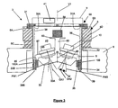
- the air plane 1 is provided with a device 3 for taking successive images of the ground 2, when flying according to a flight mission (for example in the flight direction X).
- the device 3 comprises a series of independent camera modules (for example four camera modules 4 for taking different images along different view axis).
- Each camera module has a central optical axis OA1,OA2 and have a field of view FW1,FW2 defined by an angle W (see figures 2 and 3 ).
- the device 3 represented in figure 3 is mounted on a stabilized suspension 5 mounted on the bottom 6 of the aircraft 1, said suspension is controlled by motors (not shown) adapted for correcting the position of the device 3 in function of the movement of the air plane, for example due to air turbulence.
- the suspension 5 comprises a support 5B which can rotate around two substantially horizontal axes H1,H2 and which comprises a rotating ring plate 5A able to rotate around a substantially vertical axis V1.
- the suspension 5 has a central open cylindrical chamber 5C suitable for receiving the device 3.
- the device 3 comprises :
- the camera modules 4A,4B,4C,4D are fixed on the support 8 by screwing or by a clipping mechanism.
- the camera modules can be removed from the support 8.
- the system enables thus the use of another support 8 with the same camera modules, for example for having a different overlapping of the fields of view or to use different lenses for the camera modules with a different support for taking images at a different height.
- Each camera module comprises :
- the first portion 50 of the camera module comprises a rigid carrier 72 on which is mounted the flexure piezo positioner 53 bearing the framing sensor 51.
- the flexure positioner 53 is mounted and maintained in position by means (such as screws, clips, etc.) enabling an easy removal of the piezo positioner 53 with the frame sensor. In this way, in case a problem arises to the framing sensor or to the flexure piezo positioner, it is possible during the flight to replace the possibly defect piezo positioner with framing sensor by another piezo positioner with framing sensor or by a simple framing sensor.
- the second portion 54 of the camera module is also provided with one or more optical glasses 55bis adapted for the passage of specific waves (electromagnetic waves) suitable, after being collected by the image framing sensor and converted in digital form in the electronic system 58, to be treated in the computer so as to give a very precise image.
- specific waves electromagnettic waves
- the optical glass or glasses can be for example a protection glass (such as a glass ensuring protection against environment, abrasion, particles, etc.), a glass having characteristics enabling after treatment of the information (received by the frame sensor, possibly pretreated in the electronic part attached to the frame sensor and treated in a computer system) to obtain one or more colour information, preferably several colour information in the multispectral wave length range or partial multispectral wave length range (such as from multispectral camera modules) and/or black/white information in the panchromatic band range (such as for panchromatic camera module) and/or infrared information IR in the IR wave length range or partial IR wave length range (such as for IR camera module) and/or a combination of such information.
- the glass or glasses are advantageously blocking the IR rays or the visible rays.
- the use of the transparent sheet 33A is optional, i.e. possibly no bottom cover 33 is used.
- the framing sensor is free of element or layer or film (such as protection film/layer) inducing possible diffraction or disturbance, which could lead to a lack of precision.
- a framing sensor suitable to collect information in the IR band, in the multispectral band and in the Black/white band it is possible by using one or more optical glasses to collect by the framing sensor one or more information in the IR band, in the multispectral band and/or in the black/white band.
- a same framing sensor can thus be used for collecting different information of the image.
- the camera module is also provided with a heat isolation means, such as an insulation layer, for example an insulation layer 40A covering the lateral side of the second portion 54 of the camera module and possibly the lateral edges of the optical glass or glasses 55 bis.
- a heat isolation means such as an insulation layer, for example an insulation layer 40A covering the lateral side of the second portion 54 of the camera module and possibly the lateral edges of the optical glass or glasses 55 bis.
- the first portion 50 of the camera module can also be provided with an insulation layer 40B.
- the camera module can also be provided with a heating element 41, said heating element 41 such as a heating wire or band is for example attached to the rigid carrier 72, for example on an inner face of the carrier 72.
- the heating element 41 is controlled by a control system 41bis (such as a thermostat), so as to maintain the temperature in the inner chamber of the camera module (environment in contact with the framing sensor) with a specific range of temperature (such as between 5 and 30°C) and/or so as to maintain substantially constant said temperature (temperature of about 20°C).
- a control system 41bis such as a thermostat
- the heat insulation cover 40A is associated to one or more heating elements 41 (with control system or thermostat 41bis), so as to ensure a minimum temperature for the glasses 55, as well for the shutter 56.
- the electronic part 58 of the sensor is not fixed on the plate 52, but is connected via wires 58A to the sensor 51.
- the movement of the plate is made in a direction parallel to the flight direction X of the air plane.
- the movement of said plate is controlled by a system 60 receiving information from the air plane (such as speed) so as to compensate the movement of the air plane with respect to the ground to be photographed during the exposure time of the sensor.
- the movement (X1) of the plate 52 and thus of the framing sensor 51 is parallel to the movement of the air plane (X) during the exposure time so as to compensate the movement of the air plane during the exposure time.
- Figure 9 shows the end movement of the plate 52, before its return in the initial position.
- the movement speed of the plate increases first progressively to a constant speed. Said constant speed is then maintained during a time period of a few milliseconds, such as 10 milliseconds or 20 milliseconds.
- the variation of speed of the plate 52 is represented in figure 14 .
- the shutter 56 is controlled so that the exposure time (for example 1/500 second or 1/1000 second) is made during a movement of the plate 52 (i.e. of the sensor) at a constant speed.
- Figures 10 and 11 show another camera module similar to the camera module of figure 8 , except that the electronic system 58 is attached to a supporting piece 70 having two opposite edges 70A,70B.
- the opposites edges 70A are respectively attached to a left flexure piezo positioner 53A and to a right flexure piezo positioner 53B.
- the movement of the supporting piece 70 is guided by two parallel rails 59.
- the framing sensor 51 is directly connected to its electronic part 58.
- a cover 71 is attached to a rigid carrier 72 so as to form a protection for the flexure piezo positioners and the electronic part. In figure 10 , the protective cover 71 was removed.
- the camera module of figures 10 and 11 is also provided with optical glasses 55bis, insulation layers 40A,40B, and heating elements 41 with control means 41bis.
- the electronic system is attached to a supporting piece, which is connected to one single flexure piezo positioner for controlling the movement of the framing sensor.
- Figures 12 and 13 show still another camera module similar to the camera module of figure 8 .
- the plate 52 of the flexure piezo positioner 53 has a central opening 52A.
- the framing sensor 51 is placed above said opening, while the electronic part 58 is directly attached to the plate 52.
- the framing sensor 51 is directly connected to its electronic part 58.
- the framing sensor is placed at least partly in said opening 52A, while still according to another possible embodiment, a part of the electronic part 58 extends through the opening 52A, while the framing sensor is located below the plate 52 towards the glasses 55.
- a cover 71 (attached to the rigid support 72) can be used for protecting the electronic part 58 of the framing sensor 51.
- the camera module of figures 12 and 13 is also provided with optical glasses 55bis, insulation layers 40A,40B, and heating elements 41.
- the plate (52) of the piezo positioner 53 bears on one of its faces a box for receiving the electronic part 58 on which is attached the framing sensor.
- Figure 15 is a view of another support 8 which is provided with the portion 54 (comprising the lenses and the shutter).
- the portion of the camera module 50 with the framing sensor is mounted detachable with respect to the support 8.
- the first portion of the camera modules can for example be clipped on the fixation means 57.
- the support 8 can be provided with bottom protection covers for the lenses, said protection covers being provided with detachable glasses or with fixed glasses.
- a support provided with bottom protection covers 33 and with detachable glasses 33A is shown.
- the glasses 33A are mounted detachably on the bottom protection covers 33 so as to close openings.
- the glasses 33A can be maintained in position by various mechanisms, such as clips, screws, etc. After removing the support 8 from the receptacle, it is possible to remove the glasses 33A from the bottom protection covers 33 of the removed support 8 and to place said glasses on the bottom protection covers of another support 8.
- no bottom protection covers can be used, as one optical glass acts as protection for the camera module.
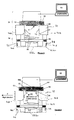
- the camera modules 4A and 4C take views of the ground at a time "T1", while the camera modules take views at a time "T2" different from time "T1", whereby enabling a transfer of data of the camera modules to a data treatment system during the taking of images by the camera modules 4B and 4D.
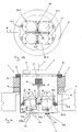
- Figure 24 is a figure similar to figure 3 , except that the rigid support 8 has a horizontal face provided with openings 80 adapted for working with ring seats 63, which are profiled so as to give the inclination for the camera modules.
- the ring seats 63 can easily be replaced so as to adapt the inclination of the bearing surface of the seat (and thus of the optical axis of the camera module), for example an angle of 5°, 7.5°, 10°, 12.5°, 15°; 20°, etc.
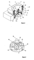
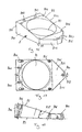
- Figure 16 is a view of a rigid support element or slope interface 8 for providing a specific direction to the central optical direction for a camera module mounted on said rigid support.
- the device comprises several camera modules
- the support elements are placed adjacent to each other in the frame 30.
- the frame 30 is shown in figures 19 and 20 .
- the support element 8 is provided with a passage 80 having a seat 81 formed by the upper surface of the element 8, said upper face being inclined with respect to the bottom face 89.
- said frame 30 (for example made at least partly of composite materials) is provided at its bottom 300 with a plate 301 with four view openings 301A.
- the plate 301 bears screwing rods 303 adapted for guiding the placement and the position of the support elements 8.
- the supporting element 8 is provided with three holes 800 for enabling the passage of three screwing rods 303, whereby a fixation of the support can be achieved by bolts 304.
- the fixation of the camera module 4 is achieved by screws 805, the end of which is screwed in the holes 806 of the support element 8.
- the placement of the support element 8 on the plate 301 can be operated after mounting the camera module on the support element or slope interface 8.
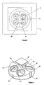
- FIG 21 shows schematically the four framing sensors 51A,51B,51C,51D of four camera modules 4 placed in a frame 30.
- Each framing sensor is associated to a set of glasses and to a shutter, said glasses defining a circular viewing image or zone VZ1,VZ2,VZ3, VZ4 with respective optical axis OA1,OA2,OA3,OA4.
- Each framing sensor 51A,51B,51C,51D is not centred with respect to the optical axis, but is placed in a zone of the viewing image for which the distorsion and modulation of the image is acceptable.
- Each framing sensor is adapted so as to take a view of the image along the optical axis through optical lenses or glasses 55 (see also figure 22 ).
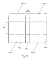
- the images taken by the framing sensors 51A and 51B comprised a zone 510 comprising the optical axis of the glasses (OA1, OA2), and a side zone (511,512) located on the left or the right of the zone 510.
- the merging of the images taken by the sensors 51A,51B is carried out so as to form an image comprising the zones 510,511,512.
- the fact that the sensors 51A,51B take images with a portion including the optical axis view enables a quicker merging of the images.
- the overlapping of two successive images is for example comprised between 25 and 85%, such as about 50 - 60%, whereby enabling a very good merging of two successive images taken at different times (tl, t2).
- sensors 51A,51B,51C and 51D When using sensors 51A,51B,51C and 51D with a vertical optical axis, it is easily possible to determine the matching of the picture in the central zone comprising the optical axis. In this case, the sensors 51A,51B,51C,51D will take images with the optical axis in a corner portion of the sensor, it is possible to combine together the four images by merging the portions with the optical axis of said images taken by the four sensors.
- Figure 25 is a view of a device similar to the device shown in figure 24 .
- An insulation envelope 40A with a protection glass 55bis is used for protecting the shutter and the glasses, said insulation envelope 40A being provided with a heating system 41.
- the frame 30 is made of composite material with insulation properties.
- the bottom of the frame 30 is provided with a removable protection plate 500, said plate closing the frame 30 during a takeoff and landing of the air plane so as to provide a full protection of the camera modules.
- the plate 500 is removed when images have to be taken, i.e. when the air plane is at the right altitude. The removal of the plate can be made by a motorized device.
- the device is also provided with a system for controlling or adapting the focal distance of the glasses or lenses to the infinity (i.e. for focusing on the infinity).
- Said adapting step is made by rotating the lenses and shutter with respect to the frame associated with the framing sensor, so as to modify the distance between the framing sensor and the glasses and lenses.
- screws or bolts are used so as to maintain into position the piece with the shutter with respect to a piece associated to the framing sensor.
Landscapes
- Engineering & Computer Science (AREA)
- Multimedia (AREA)
- Signal Processing (AREA)
- Physics & Mathematics (AREA)
- General Physics & Mathematics (AREA)
- Radar, Positioning & Navigation (AREA)
- Remote Sensing (AREA)
- Studio Devices (AREA)
- Aiming, Guidance, Guns With A Light Source, Armor, Camouflage, And Targets (AREA)
- Accessories Of Cameras (AREA)
- Closed-Circuit Television Systems (AREA)
- Radar Systems Or Details Thereof (AREA)
Claims (20)
- Un module caméra (4) pour la prise d'images à partir d'un engin volant (1) se déplaçant dans une direction de vol (X), ledit module caméra (4) comprenant une première partie (50) avec au moins un capteur matriciel (51) et une seconde partie (54) comprenant au moins un élément de vision sélectionné dans le groupe constitué d'objectifs, lentilles (55), verres optiques et combinaisons de ceux-ci, dans lequel le module caméra (4) a un axe optique central (OA1,OA2), ledit capteur matriciel (51) étant muni d'un moyen (58) pour transférer des données récoltées par le capteur matriciel (51) vers un élément sélectionné dans le groupe constitué de mémoire de données, d'un système de traitement de données et d'une combinaison de ces derniers, et au moins un élément pour assurer une compensation de filés ou mouvement en avant, dans lequel le module caméra (4) est adapté pour la prise de vue dans un temps exposition de moins de 0,1 seconde, le capteur matriciel (51) du module caméra (4) est monté de manière mobile par rapport à la seconde partie (54), le capteur matriciel (51) est libre d'éléments, de couches ou films induisant une diffraction ou une perturbation, et le capteur matriciel (51) est associé à un élément piézoélectrique de positionnement (53) assurant au moins un mouvement du capteur matriciel (51) à une vitesse sensiblement constante pour un temps plus long que le temps d'exposition, ledit élément piézoélectrique de positionnement (53) étant adapté pour agir comme moyen de compensation du mouvement en avant de l'engin volant pour le capteur matriciel (51) du module caméra.
- Le module caméra de la revendication 1, caractérisé en ce que l'élément piézoélectrique de positionnement (53) assure un mouvement du capteur matriciel (51) de moins de 100µm a une vitesse sensiblement constante pour un temps plus long que le temps d'exposition, ledit élément piézoélectrique de positionnement (53) étant adapté pour agir comme moyen de compensation du mouvement en avant de l'engin volant pour le capteur matriciel (51) du module caméra.
- Le module caméra de la revendication 1 ou 2, dans lequel le capteur matriciel (51) est associé à un élément piézoélectrique de positionnement (53) assurant au moins un mouvement du capteur à une vitesse sensiblement constante pour un temps plus long que deux fois le temps d'exposition, avantageusement compris entre 5 et 100 fois le temps d'exposition, ledit élément piézoélectrique de positionnement (53) étant adapté pour agir comme moyen de compensation du mouvement en avant de l'engin volant pour le capteur matriciel (51) du module caméra.
- Le module caméra selon l'une des revendications 1 à 3, dans lequel l'élément piézoélectrique de positionnement agissant comme moyen de compensation du mouvement en avant de l'engin volant pour le capteur matriciel (51) du module caméra comprend une plaque (52) guidée par des rails de guidage (59).
- Le module caméra selon l'une des revendications 1 à 4, qui est sélectionné dans le groupe constitué de modules caméra IR, modules caméra multispectrale, modules caméra monochrome, modules caméras panchromatique, et des combinaisons de ces derniers.
- Le module caméra selon l'une des revendications 1 à 5, qui comprend une pièce de support (70) supportant le capteur matriciel (51), ainsi que les moyens de contrôle électronique (58) pour ledit capteur matriciel (51), ladite pièce de support (70) ayant une première arête (70A) et une seconde arête (70B) opposée à la première arête (70A), dans lequel le module (4) comprend deux capteurs piézoélectriques (53A,53B) ayant chacun une partie mobile, la partie mobile du premier élément piézoélectrique de positionnement (53A) étant attachée à la première arête de la pièce de support (70), alors que la partie mobile du second élément piézoélectrique de positionnement (53B) est attachée à la seconde arête de la pièce de support (70).
- Le module caméra selon l'une des revendications 1 à 6, dans lequel l'élément piézoélectrique de positionnement (53) comprend une plaque mobile (52), dans lequel le capteur matriciel (51) est associé à une partie électronique (58) qui est attachée à la plaque (52) et dans lequel la plaque mobile (52A) a une ouverture pour le capteur matriciel (51) pour permettre au capteur matriciel (51) de prendre des prises de vue.
- Une caméra comprenant au moins un module caméra conformément à n'importe laquelle des revendications 1 à 7.
- Dispositif (3) pour caméras (4) pour la prise d'images d'un objet ou d'une surface, ledit dispositif (3) étant adapté pour être monté sur un système de suspension stabilisé (5) pour être monté sur un véhicule mobile (1) bougeant à une vitesse relative supérieure à 100km/heure par rapport à l'objet ou la surface à prendre en images, ledit dispositif comprenant :- un cadre (30),- au moins deux modules caméra (4A,4B,4C,4D) selon l'une quelconque des revendications 1 à 7 pour prendre une première série de prises de vue par le premier module caméra (4A) et une seconde série de prises de vue par le deuxième module caméra (4B), chaque module caméra (4A,4B) comprenant une première partie (50) comprenant un capteur matriciel (51) et une seconde partie (54) comprenant au moins un élément de visualisation sélectionné dans le groupe constitué d'objectifs, de lentilles (55), de verres optiques et de combinaisons de ceux-ci, dans lequel chaque module caméra (4A,4B) a un axe optique central (OA1,OA2), ledit capteur matriciel (51) étant pourvu d'un moyen (58) pour transférer des données récoltées par le capteur matriciel (51) vers un élément sélectionné dans le groupe constitué de mémoire de données, systèmes de traitement de données, ainsi que des combinaisons de ceux-ci, et- un moyen (8) adapté pour orienter l'axe optique central (OA1,OA2) de chaque module caméra (4A,4B) par rapport au cadre (30),dans lequel le moyen (8) pour orienter l'axe optique central de chaque module caméra (4A,4B) est adapté pour orienter au moins l'axe optique central (OA1) d'un premier module caméra (4A) par rapport à l'axe optique central (OA2) d'un deuxième module caméra (4B), de préférence pour orienter au moins l'axe optique central (OA1) d'un premier module caméra (4A) et l'axe optique central (OA2) d'un deuxième module caméra (4B), pour que le premier module caméra (4A) et le deuxième module caméra (4B) aient un recouvrement des champs angulaires (FW1,FW2), dans lequel ledit moyen d'orientation (8) est monté de manière démontable par rapport au cadre (30), alors qu'au moins la première partie (50) du(des) module(s) caméra (4A,4B) est monté de manière démontable par rapport audit moyen d'orientation (8).
- Le dispositif de la revendication 9, dans lequel le moyen d'orientation de l'axe optique central (OA1,OA2) des modules caméra (4A,4B) est un support rigide (8) prévu avec au moins deux passages (80), chaque passage étant associé à au moins un élément siège (81) adapté pour supporter au moins une partie du module caméra (4A,4B), le support rigide (8) étant avantageusement muni d'un bras (82) portant un module inertiel (84).
- Le dispositif des revendications 9 ou 10, dans lequel le moyen d'orientation (8) est un support prévu avec au moins deux passages (80), chaque passage (80) étant associé à au moins un élément siège (81) adapté pour supporter une partie du module caméra (4A,4B), dans lequel une premier siège (81) est adapté pour diriger l'axe optique central (OA1) d'un premier module caméra (4A) dans une première direction, tandis qu'un deuxième siège (81) est adapté pour diriger l'axe optique central (OA2) d'un second module caméra (4B) dans une seconde direction, où les première et deuxième directions (OA1,OA2) sont adaptées afin d'assurer un recouvrement (OZ) du champ angulaire (FW1) du premier module caméra (4A) avec le champ angulaire (FW2) du second module caméra (4B).
- Le dispositif selon l'une des revendications 9 à 11, dans lequel la seconde partie (54) d'un module caméra (4A) est montée sur la première partie (50) dudit module caméra (4A) de manière démontable et dans lequel au moins un moyen d'attache (57) est adapté pour maintenir la seconde partie (54) en position par rapport à la première partie (50) du module caméra (4).
- Le dispositif selon l'une des revendications 9 à 11, dans lequel la seconde partie (54) du module caméra (4) est attachée au moyen d'orientation (8) de l'axe optique central (OA1, OA2) du module caméra (4A, 4B).
- Le dispositif selon l'une des revendications 9 à 13, dans lequel le moyen d'orientation (8) de l'axe optique central (OA1, OA2) du module caméra (4A, 4B) est connecté au cadre (30) par l'interposition d'un moyen d'absorption de vibrations (100).
- Le dispositif selon l'une des revendications 9 à 14, dans lequel le moyen d'orientation (8) est un support prévu avec au moins quatre passages (80), chaque passage (80) étant associé à au moins un élément siège (81) adapté pour accueillir une partie du module caméra (4A,4B), dans lequel un premier siège (81) est adapté pour diriger l'axe optique central (OA1) d'un premier module caméra (4A) dans une première direction, un deuxième siège (81) est adapté pour diriger l'axe optique central (OA2) d'un deuxième module caméra (4B) dans une deuxième direction, un troisième siège (81) est adapté pour diriger l'axe optique central (OA3) d'un troisième module caméra (4C) dans une troisième direction et un quatrième siège (81) est adapté pour diriger l'axe optique central (OA4) d'un quatrième module caméra (4D), où les première et deuxième directions (OA1,OA2) sont adaptées pour assurer un recouvrement (OZ) du champ angulaire (FW1) du premier module caméra (4A) et du champ angulaire (FW2) du second module caméra (4B), tandis que les troisième et quatrième directions sont adaptées pour assurer un recouvrement du champ angulaire du troisième module caméra et du champ angulaire du quatrième module caméra.
- Le dispositif selon l'une des revendications 9 à 15, dans lequel le cadre est un réceptacle (30) prévu avec au moins deux passages, un premier passage étant adapté pour placer les moyens (8) pour diriger les axes optique centraux (OA1,OA2) des modules caméra (4A,4B) au moins partiellement dans le réceptacle (30), tandis que le deuxième passage est adapté pour assurer les champs angulaires (FW1,FW2) des modules caméras, et dans lequel le réceptacle (30) est prévu avec le moyen (35) pour soutenir le moyen (8) pour diriger les axes optique centraux (OA1,OA2) des modules caméra (4A,4B) avec l'interposition d'un moyen d'absorption de vibrations (100), le réceptacle (30) étant avantageusement prévu avec un moyen pour associer le réceptacle sur une suspension stabilisée (5), préférablement le réceptacle (30) étant prévu avec un couvercle (9) et un élément de fond (33) avec des feuilles transparentes (33A) pour définir une chambre sensiblement fermée pour les modules caméra (4A,4B), tandis que le dispositif comprend en outre un élément de chauffage (41) pour assurer une température sensiblement constante dans le réceptacle (30).
- Le dispositif de la revendication 9, dans lequel le moyen pour orienter les axes optique centraux (OA1, OA2) d'au moins deux modules caméra (4A, 4B) comprend au moins deux éléments distincts (8), un premier (8) étant conçu pour orienter l'axe central (OA1) d'un premier module caméra (4A), tandis qu'un second (8) est conçu pour orienter l'axe central (OA2) d'un deuxième module caméra (4B) distinct du premier (4A).
- Un engin volant muni d'au moins une caméra selon la revendication 8.
- Un engin volant muni de caméras (4A, 4B) pour prendre des prises de vue d'un objet ou d'une surface, ledit engin volant (1) comprenant une suspension stabilisée (5) sur lequel un dispositif (3) selon l'une quelconque des revendications 9 à 17 avec des modules caméra distincts (4A, 4B) est monté.
- Un procédé de prise de vues d'un objet ou d'une surface pendant un vol d'un engin volant (1) dans une direction, ledit engin volant étant muni de caméras (4A,4B), d'où ledit engin volant (1) comprend une suspension stabilisée (5) sur lequel un dispositif (3) avec au moins un module caméra (4A) est monté, dans lequel au moins un module caméra (4A) comprend une première partie (50) avec un capteur matriciel (51) et une seconde partie (54) avec au moins un élément de vision sélectionné dans le groupe constitué d'objectifs, de lentilles (55), de verres optiques et de combinaisons de ceux-ci, dans lequel le module caméra (4A) a un axe optique central (OA1), ledit capteur matriciel (51) étant muni d'un moyen (58) pour transférer des données recueillies par le senseur à un élément (60) sélectionné dans le groupe constitué de mémoire de données, système de traitement de données, et de combinaisons de ceux-ci, dans lequel le module caméra (4A) est adapté pour la prise de vue avec un temps d'exposition de moins de 0,1 seconde, dans lequel le capteur matriciel (51) du module caméra est monté par rapport à la seconde partie (54), ledit module caméra étant un module caméra selon l'une quelconque des revendications 1 à 7, comprenant l'étape de :déplacer le capteur matriciel par un élément piézoélectrique de positionnement (53), avantageusement sur moins de 100µm, à une vitesse contrôlée sensiblement constante pour un temps plus long que le temps d'exposition afin d'assurer une compensation du mouvement en avant de l'image prise pendant le vol.
Applications Claiming Priority (5)
| Application Number | Priority Date | Filing Date | Title |
|---|---|---|---|
| US318894 | 2002-12-13 | ||
| US10/318,894 US7365774B2 (en) | 2002-12-13 | 2002-12-13 | Device with camera modules and flying apparatus provided with such a device |
| WOPCT/BE03/00025 | 2003-02-13 | ||
| BE0300025 | 2003-02-13 | ||
| PCT/BE2003/000218 WO2004055588A1 (fr) | 2002-12-13 | 2003-12-12 | Dispositif pourvu de modules de camera et appareil volant equipe de ce dispositif |
Publications (2)
| Publication Number | Publication Date |
|---|---|
| EP1570314A1 EP1570314A1 (fr) | 2005-09-07 |
| EP1570314B1 true EP1570314B1 (fr) | 2008-04-23 |
Family
ID=32506495
Family Applications (1)
| Application Number | Title | Priority Date | Filing Date |
|---|---|---|---|
| EP03782016A Expired - Lifetime EP1570314B1 (fr) | 2002-12-13 | 2003-12-12 | Dispositif pourvu de modules de camera et appareil volant equipe de ce dispositif |
Country Status (8)
| Country | Link |
|---|---|
| US (1) | US7365774B2 (fr) |
| EP (1) | EP1570314B1 (fr) |
| AT (1) | ATE393412T1 (fr) |
| AU (1) | AU2003289769A1 (fr) |
| CA (1) | CA2509540C (fr) |
| DE (1) | DE60320580T2 (fr) |
| ES (1) | ES2308006T3 (fr) |
| WO (1) | WO2004055588A1 (fr) |
Cited By (3)
| Publication number | Priority date | Publication date | Assignee | Title |
|---|---|---|---|---|
| EP2253932A1 (fr) | 2009-05-19 | 2010-11-24 | Leica Geosystems AG | Système de caméra aérienne et procédé de correction de distorsions lors d'une image aérienne |
| US8548313B2 (en) | 2010-09-30 | 2013-10-01 | Trimble Germany Gmbh | Aerial digital camera and method of controlling the same |
| EP3916351A1 (fr) | 2020-05-29 | 2021-12-01 | Leica Geosystems AG | Corps de caméra à stabilisation fmc mécanique pour un dispositif de surveillance aérien ou spatial |
Families Citing this family (20)
| Publication number | Priority date | Publication date | Assignee | Title |
|---|---|---|---|---|
| US8483960B2 (en) | 2002-09-20 | 2013-07-09 | Visual Intelligence, LP | Self-calibrated, remote imaging and data processing system |
| US8994822B2 (en) | 2002-08-28 | 2015-03-31 | Visual Intelligence Lp | Infrastructure mapping system and method |
| US7893957B2 (en) * | 2002-08-28 | 2011-02-22 | Visual Intelligence, LP | Retinal array compound camera system |
| USRE49105E1 (en) | 2002-09-20 | 2022-06-14 | Vi Technologies, Llc | Self-calibrated, remote imaging and data processing system |
| US9182228B2 (en) * | 2006-02-13 | 2015-11-10 | Sony Corporation | Multi-lens array system and method |
| US20080100711A1 (en) * | 2006-10-26 | 2008-05-01 | Wisted Jeffrey M | Integrated Multiple Imaging Device |
| US7643063B2 (en) * | 2006-12-29 | 2010-01-05 | The Boeing Company | Dual loop stabilization of video camera images |
| US20130100342A1 (en) * | 2009-12-15 | 2013-04-25 | Lite-On Technology Corp. | Image capturing device |
| RU2498378C1 (ru) * | 2012-06-21 | 2013-11-10 | Александр Николаевич Барышников | Способ получения изображения земной поверхности с движущегося носителя и устройство для его осуществления |
| ES2535205B1 (es) * | 2013-11-04 | 2016-02-24 | Universidad De Salamanca | Plataforma fotogramétrica |
| WO2017058901A1 (fr) | 2015-09-28 | 2017-04-06 | Ball Aerospace & Technologies Corp. | Lidar à absorption différentielle |
| CN105444740A (zh) * | 2016-01-01 | 2016-03-30 | 三峡大学 | 一种基于小型无人机遥感辅助滑坡应急治理工程勘查设计方法 |
| CN106324632A (zh) * | 2016-08-01 | 2017-01-11 | 北京艾森博航空科技股份有限公司 | 无控制点条件下的植保无人机精确定位方法 |
| US11463610B2 (en) * | 2017-05-10 | 2022-10-04 | Mobileye Vision Technologies Ltd. | Cross field of view for autonomous vehicle systems |
| US10514554B2 (en) * | 2017-09-30 | 2019-12-24 | Pixart Imaging Inc. | Optical motion detecting device for a flight vehicle |
| CN208353436U (zh) * | 2018-02-09 | 2019-01-08 | 瑞声科技(新加坡)有限公司 | 图像采集模组 |
| US10921245B2 (en) | 2018-06-08 | 2021-02-16 | Ball Aerospace & Technologies Corp. | Method and systems for remote emission detection and rate determination |
| EP3748286A1 (fr) | 2019-06-03 | 2020-12-09 | Carl Zeiss Industrielle Messtechnik GmbH | Appareil d'imagerie et procédé de fonctionnement d'un appareil d'imagerie |
| WO2022135632A1 (fr) * | 2020-12-22 | 2022-06-30 | Sam - Dimension Ug (Haftungsbeschränkt) | Appareil et procédé de cartographie de zone |
| GB2613148B (en) * | 2021-11-19 | 2024-02-21 | New Space Optics Ltd | Earth observation scanning system |
Family Cites Families (12)
| Publication number | Priority date | Publication date | Assignee | Title |
|---|---|---|---|---|
| US2003A (en) * | 1841-03-12 | Improvement in horizontal windivhlls | ||
| GB1285707A (en) | 1968-10-09 | 1972-08-16 | G N Drinkwater & Son Ltd | Improvements in and relating to tools for lathes |
| US3744387A (en) * | 1971-10-08 | 1973-07-10 | D Fuller | Camera with apparent image motion and direction compensation |
| US3902084A (en) * | 1974-05-30 | 1975-08-26 | Burleigh Instr | Piezoelectric electromechanical translation apparatus |
| EP0563737B1 (fr) * | 1992-03-23 | 1997-09-10 | Canon Kabushiki Kaisha | Appareil de prise de vues multi-lentilles avec correction de désalignement |
| DE19502045C2 (de) | 1995-01-12 | 1998-01-08 | Deutsche Forsch Luft Raumfahrt | Vorrichtung zur Kompensation von Bildverwaschungen |
| US5949477A (en) * | 1995-04-06 | 1999-09-07 | Hoglin; Irving M. | Three dimensional stereoscopic television system |
| JPH1077141A (ja) * | 1996-07-09 | 1998-03-24 | Nikon Corp | フィルム給送装置及び画像読取装置 |
| US5897223A (en) | 1997-11-17 | 1999-04-27 | Wescam Inc. | Stabilized platform system for camera |
| DE10034601B4 (de) * | 2000-07-14 | 2013-05-23 | Leica Geosystems Ag | Kamerasystem mit mindestens zwei ersten und zweiten Kameras |
| EP1178283A1 (fr) | 2000-07-31 | 2002-02-06 | CO.RI.AL. Consorzio Ricerche Alimentari S.C.p.A. | Systéme d' imagerie aérienne spectrale avec caméra digitale |
| US6831688B2 (en) * | 2002-04-08 | 2004-12-14 | Recon/Optical, Inc. | Multispectral or hyperspectral imaging system and method for tactical reconnaissance |
-
2002
- 2002-12-13 US US10/318,894 patent/US7365774B2/en not_active Expired - Lifetime
-
2003
- 2003-12-12 DE DE60320580T patent/DE60320580T2/de not_active Expired - Lifetime
- 2003-12-12 WO PCT/BE2003/000218 patent/WO2004055588A1/fr not_active Ceased
- 2003-12-12 AU AU2003289769A patent/AU2003289769A1/en not_active Abandoned
- 2003-12-12 AT AT03782016T patent/ATE393412T1/de active
- 2003-12-12 ES ES03782016T patent/ES2308006T3/es not_active Expired - Lifetime
- 2003-12-12 EP EP03782016A patent/EP1570314B1/fr not_active Expired - Lifetime
- 2003-12-12 CA CA2509540A patent/CA2509540C/fr not_active Expired - Lifetime
Cited By (7)
| Publication number | Priority date | Publication date | Assignee | Title |
|---|---|---|---|---|
| EP2253932A1 (fr) | 2009-05-19 | 2010-11-24 | Leica Geosystems AG | Système de caméra aérienne et procédé de correction de distorsions lors d'une image aérienne |
| US9154717B2 (en) | 2009-05-19 | 2015-10-06 | Leica Geosystems Ag | Aerial camera system and method for correcting distortions in an aerial photograph |
| US8548313B2 (en) | 2010-09-30 | 2013-10-01 | Trimble Germany Gmbh | Aerial digital camera and method of controlling the same |
| US8699867B2 (en) | 2010-09-30 | 2014-04-15 | Trimble Germany Gmbh | Aerial digital camera and method of controlling the same |
| EP3916351A1 (fr) | 2020-05-29 | 2021-12-01 | Leica Geosystems AG | Corps de caméra à stabilisation fmc mécanique pour un dispositif de surveillance aérien ou spatial |
| EP4008995A2 (fr) | 2020-05-29 | 2022-06-08 | Leica Geosystems AG | Corps de caméra à stabilisation fmc mécanique pour un dispositif de surveillance aérien ou spatial |
| US11800225B2 (en) | 2020-05-29 | 2023-10-24 | Leica Geosystems Ag | Camera body with mechanical FMC stabilization for an airborne or spaceborne surveying device |
Also Published As
| Publication number | Publication date |
|---|---|
| DE60320580T2 (de) | 2009-06-04 |
| ES2308006T3 (es) | 2008-12-01 |
| EP1570314A1 (fr) | 2005-09-07 |
| US20040114038A1 (en) | 2004-06-17 |
| WO2004055588A1 (fr) | 2004-07-01 |
| ATE393412T1 (de) | 2008-05-15 |
| CA2509540C (fr) | 2013-09-24 |
| CA2509540A1 (fr) | 2004-07-01 |
| DE60320580D1 (de) | 2008-06-05 |
| US7365774B2 (en) | 2008-04-29 |
| AU2003289769A1 (en) | 2004-07-09 |
Similar Documents
| Publication | Publication Date | Title |
|---|---|---|
| EP1570314B1 (fr) | Dispositif pourvu de modules de camera et appareil volant equipe de ce dispositif | |
| CA2248650C (fr) | Mosaique de detecteurs pour imagerie electro-optique, a compensation de file sur deux axes | |
| CA2462603C (fr) | Camera a mode stereoscopique a angle de relevement constant eleve | |
| US4908705A (en) | Steerable wide-angle imaging system | |
| US5864363A (en) | Method and device for automatically taking a picture of a person's face | |
| US20140340474A1 (en) | Panoramic image scanning device using multiple rotating cameras and one scanning mirror with multiple surfaces | |
| CA2613449C (fr) | Systeme de stabilisation d'image | |
| KR100316458B1 (ko) | 가동성차폐부재가구비된3차원및2차원의이중모드카메라 | |
| US4222653A (en) | Visual effects optical relay | |
| WO2002019030A9 (fr) | Camera de reconnaissance a double bande avec compensation du roulis | |
| CA2140681C (fr) | Systeme de recherche infrarouge a grande couverture | |
| Lareau | Advancements in EO framing | |
| RU2062983C1 (ru) | Оптико-электронная система наблюдения и регистрации | |
| Augustyn | The KS-146A long range oblique photography (LOROP) camera system | |
| JP3004729U (ja) | マルチ画面撮影装置における撮り分け装置 | |
| Amsbury | Expanding the utility of manned observations of earth: 70 mm film tests on the space shuttle | |
| Nicolai | The MSK-4 multispectral camera, a new high-performance photographic system | |
| McLaurin et al. | Single-source three-dimensional imaging system for remote sensing | |
| DIETE | LMK-2000- A new aerial survey camera system | |
| SU940135A1 (ru) | Устройство управлени стереоскопической телевизионной камерой | |
| GB2269260A (en) | Digital array exposure apparatus | |
| Uhl | The new light weight, high performance reconnaissance camera KRb 8/24 F | |
| Radziemski Jr | Near infrared photography of the outer corona during the 30 June 1973 solar eclipse | |
| Eyton | Student Aerial Photography | |
| JPH08292467A (ja) | レンズカバー及び撮影装置 |
Legal Events
| Date | Code | Title | Description |
|---|---|---|---|
| PUAI | Public reference made under article 153(3) epc to a published international application that has entered the european phase |
Free format text: ORIGINAL CODE: 0009012 |
|
| 17P | Request for examination filed |
Effective date: 20050628 |
|
| AK | Designated contracting states |
Kind code of ref document: A1 Designated state(s): AT BE BG CH CY CZ DE DK EE ES FI FR GB GR HU IE IT LI LU MC NL PT RO SE SI SK TR |
|
| AX | Request for extension of the european patent |
Extension state: AL LT LV MK |
|
| DAX | Request for extension of the european patent (deleted) | ||
| 17Q | First examination report despatched |
Effective date: 20060510 |
|
| 17Q | First examination report despatched |
Effective date: 20060510 |
|
| GRAP | Despatch of communication of intention to grant a patent |
Free format text: ORIGINAL CODE: EPIDOSNIGR1 |
|
| GRAS | Grant fee paid |
Free format text: ORIGINAL CODE: EPIDOSNIGR3 |
|
| GRAA | (expected) grant |
Free format text: ORIGINAL CODE: 0009210 |
|
| AK | Designated contracting states |
Kind code of ref document: B1 Designated state(s): AT BE BG CH CY CZ DE DK EE ES FI FR GB GR HU IE IT LI LU MC NL PT RO SE SI SK TR |
|
| REG | Reference to a national code |
Ref country code: GB Ref legal event code: FG4D |
|
| REG | Reference to a national code |
Ref country code: CH Ref legal event code: EP |
|
| REF | Corresponds to: |
Ref document number: 60320580 Country of ref document: DE Date of ref document: 20080605 Kind code of ref document: P |
|
| REG | Reference to a national code |
Ref country code: IE Ref legal event code: FG4D Free format text: LANGUAGE OF EP DOCUMENT: FRENCH |
|
| PG25 | Lapsed in a contracting state [announced via postgrant information from national office to epo] |
Ref country code: SI Free format text: LAPSE BECAUSE OF FAILURE TO SUBMIT A TRANSLATION OF THE DESCRIPTION OR TO PAY THE FEE WITHIN THE PRESCRIBED TIME-LIMIT Effective date: 20080423 |
|
| NLV1 | Nl: lapsed or annulled due to failure to fulfill the requirements of art. 29p and 29m of the patents act | ||
| PG25 | Lapsed in a contracting state [announced via postgrant information from national office to epo] |
Ref country code: BG Free format text: LAPSE BECAUSE OF FAILURE TO SUBMIT A TRANSLATION OF THE DESCRIPTION OR TO PAY THE FEE WITHIN THE PRESCRIBED TIME-LIMIT Effective date: 20080723 Ref country code: NL Free format text: LAPSE BECAUSE OF FAILURE TO SUBMIT A TRANSLATION OF THE DESCRIPTION OR TO PAY THE FEE WITHIN THE PRESCRIBED TIME-LIMIT Effective date: 20080423 Ref country code: FI Free format text: LAPSE BECAUSE OF FAILURE TO SUBMIT A TRANSLATION OF THE DESCRIPTION OR TO PAY THE FEE WITHIN THE PRESCRIBED TIME-LIMIT Effective date: 20080423 Ref country code: PT Free format text: LAPSE BECAUSE OF FAILURE TO SUBMIT A TRANSLATION OF THE DESCRIPTION OR TO PAY THE FEE WITHIN THE PRESCRIBED TIME-LIMIT Effective date: 20080923 |
|
| REG | Reference to a national code |
Ref country code: ES Ref legal event code: FG2A Ref document number: 2308006 Country of ref document: ES Kind code of ref document: T3 |
|
| PG25 | Lapsed in a contracting state [announced via postgrant information from national office to epo] |
Ref country code: CZ Free format text: LAPSE BECAUSE OF FAILURE TO SUBMIT A TRANSLATION OF THE DESCRIPTION OR TO PAY THE FEE WITHIN THE PRESCRIBED TIME-LIMIT Effective date: 20080423 Ref country code: SE Free format text: LAPSE BECAUSE OF FAILURE TO SUBMIT A TRANSLATION OF THE DESCRIPTION OR TO PAY THE FEE WITHIN THE PRESCRIBED TIME-LIMIT Effective date: 20080723 Ref country code: DK Free format text: LAPSE BECAUSE OF FAILURE TO SUBMIT A TRANSLATION OF THE DESCRIPTION OR TO PAY THE FEE WITHIN THE PRESCRIBED TIME-LIMIT Effective date: 20080423 |
|
| ET | Fr: translation filed | ||
| PG25 | Lapsed in a contracting state [announced via postgrant information from national office to epo] |
Ref country code: SK Free format text: LAPSE BECAUSE OF FAILURE TO SUBMIT A TRANSLATION OF THE DESCRIPTION OR TO PAY THE FEE WITHIN THE PRESCRIBED TIME-LIMIT Effective date: 20080423 Ref country code: RO Free format text: LAPSE BECAUSE OF FAILURE TO SUBMIT A TRANSLATION OF THE DESCRIPTION OR TO PAY THE FEE WITHIN THE PRESCRIBED TIME-LIMIT Effective date: 20080423 |
|
| PLBE | No opposition filed within time limit |
Free format text: ORIGINAL CODE: 0009261 |
|
| STAA | Information on the status of an ep patent application or granted ep patent |
Free format text: STATUS: NO OPPOSITION FILED WITHIN TIME LIMIT |
|
| 26N | No opposition filed |
Effective date: 20090126 |
|
| PG25 | Lapsed in a contracting state [announced via postgrant information from national office to epo] |
Ref country code: EE Free format text: LAPSE BECAUSE OF FAILURE TO SUBMIT A TRANSLATION OF THE DESCRIPTION OR TO PAY THE FEE WITHIN THE PRESCRIBED TIME-LIMIT Effective date: 20080423 |
|
| PG25 | Lapsed in a contracting state [announced via postgrant information from national office to epo] |
Ref country code: MC Free format text: LAPSE BECAUSE OF NON-PAYMENT OF DUE FEES Effective date: 20081231 |
|
| REG | Reference to a national code |
Ref country code: CH Ref legal event code: PL |
|
| PG25 | Lapsed in a contracting state [announced via postgrant information from national office to epo] |
Ref country code: LI Free format text: LAPSE BECAUSE OF NON-PAYMENT OF DUE FEES Effective date: 20081231 Ref country code: IE Free format text: LAPSE BECAUSE OF NON-PAYMENT OF DUE FEES Effective date: 20081212 Ref country code: CH Free format text: LAPSE BECAUSE OF NON-PAYMENT OF DUE FEES Effective date: 20081231 |
|
| REG | Reference to a national code |
Ref country code: GB Ref legal event code: 732E Free format text: REGISTERED BETWEEN 20091217 AND 20091223 |
|
| REG | Reference to a national code |
Ref country code: ES Ref legal event code: PC2A |
|
| REG | Reference to a national code |
Ref country code: FR Ref legal event code: TP |
|
| PG25 | Lapsed in a contracting state [announced via postgrant information from national office to epo] |
Ref country code: CY Free format text: LAPSE BECAUSE OF FAILURE TO SUBMIT A TRANSLATION OF THE DESCRIPTION OR TO PAY THE FEE WITHIN THE PRESCRIBED TIME-LIMIT Effective date: 20080423 Ref country code: HU Free format text: LAPSE BECAUSE OF FAILURE TO SUBMIT A TRANSLATION OF THE DESCRIPTION OR TO PAY THE FEE WITHIN THE PRESCRIBED TIME-LIMIT Effective date: 20081024 Ref country code: LU Free format text: LAPSE BECAUSE OF NON-PAYMENT OF DUE FEES Effective date: 20081212 |
|
| PG25 | Lapsed in a contracting state [announced via postgrant information from national office to epo] |
Ref country code: TR Free format text: LAPSE BECAUSE OF FAILURE TO SUBMIT A TRANSLATION OF THE DESCRIPTION OR TO PAY THE FEE WITHIN THE PRESCRIBED TIME-LIMIT Effective date: 20080423 |
|
| PG25 | Lapsed in a contracting state [announced via postgrant information from national office to epo] |
Ref country code: GR Free format text: LAPSE BECAUSE OF FAILURE TO SUBMIT A TRANSLATION OF THE DESCRIPTION OR TO PAY THE FEE WITHIN THE PRESCRIBED TIME-LIMIT Effective date: 20080724 |
|
| REG | Reference to a national code |
Ref country code: GB Ref legal event code: 732E Free format text: REGISTERED BETWEEN 20111208 AND 20111214 |
|
| REG | Reference to a national code |
Ref country code: DE Ref legal event code: R081 Ref document number: 60320580 Country of ref document: DE Owner name: OPTECH INC., VAUGHAN, CA Free format text: FORMER OWNER: AEROSCAN SARL, BERGEM, LU Effective date: 20111124 Ref country code: DE Ref legal event code: R082 Ref document number: 60320580 Country of ref document: DE Representative=s name: GRUENECKER, KINKELDEY, STOCKMAIR & SCHWANHAEUS, DE Effective date: 20111124 Ref country code: DE Ref legal event code: R081 Ref document number: 60320580 Country of ref document: DE Owner name: OPTECH INC., CA Free format text: FORMER OWNER: AEROSCAN SARL, BERGEM, LU Effective date: 20111124 Ref country code: DE Ref legal event code: R081 Ref document number: 60320580 Country of ref document: DE Owner name: TELEDYNE OPTECH INC., VAUGHAN, CA Free format text: FORMER OWNER: AEROSCAN SARL, BERGEM, LU Effective date: 20111124 Ref country code: DE Ref legal event code: R082 Ref document number: 60320580 Country of ref document: DE Representative=s name: GRUENECKER PATENT- UND RECHTSANWAELTE PARTG MB, DE Effective date: 20111124 |
|
| REG | Reference to a national code |
Ref country code: FR Ref legal event code: TP Owner name: OPTEH INCORPORATED, CA Effective date: 20120104 |
|
| REG | Reference to a national code |
Ref country code: ES Ref legal event code: PC2A Owner name: OPTECH INCORPORATED Effective date: 20120221 |
|
| REG | Reference to a national code |
Ref country code: AT Ref legal event code: PC Ref document number: 393412 Country of ref document: AT Kind code of ref document: T Owner name: OPTECH INCORPORATED, CA Effective date: 20120220 |
|
| REG | Reference to a national code |
Ref country code: FR Ref legal event code: PLFP Year of fee payment: 13 |
|
| REG | Reference to a national code |
Ref country code: DE Ref legal event code: R082 Ref document number: 60320580 Country of ref document: DE Representative=s name: GRUENECKER PATENT- UND RECHTSANWAELTE PARTG MB, DE Ref country code: FR Ref legal event code: PLFP Year of fee payment: 13 Ref country code: DE Ref legal event code: R081 Ref document number: 60320580 Country of ref document: DE Owner name: TELEDYNE OPTECH INC., VAUGHAN, CA Free format text: FORMER OWNER: OPTECH INC., VAUGHAN, ONTARIO, CA |
|
| REG | Reference to a national code |
Ref country code: FR Ref legal event code: CD Owner name: TELEDYNE OPTECH INCORPORATED, CA Effective date: 20151119 |
|
| REG | Reference to a national code |
Ref country code: FR Ref legal event code: PLFP Year of fee payment: 14 |
|
| REG | Reference to a national code |
Ref country code: FR Ref legal event code: PLFP Year of fee payment: 15 |
|
| REG | Reference to a national code |
Ref country code: AT Ref legal event code: HC Ref document number: 393412 Country of ref document: AT Kind code of ref document: T Owner name: TELEDYNE OPTECH INCORPORATED, CA Effective date: 20180919 |
|
| REG | Reference to a national code |
Ref country code: AT Ref legal event code: HC Ref document number: 393412 Country of ref document: AT Kind code of ref document: T Owner name: TELEDYNE OPTECH INCORPORATED, CA Effective date: 20190102 Ref country code: DE Ref legal event code: R082 Ref document number: 60320580 Country of ref document: DE Representative=s name: GRUENECKER PATENT- UND RECHTSANWAELTE PARTG MB, DE Ref country code: DE Ref legal event code: R081 Ref document number: 60320580 Country of ref document: DE Owner name: TELEDYNE DIGITAL IMAGING, INC., CA Free format text: FORMER OWNER: TELEDYNE OPTECH INC., VAUGHAN, ONTARIO, CA Ref country code: DE Ref legal event code: R082 Ref document number: 60320580 Country of ref document: DE Representative=s name: HERNANDEZ, YORCK, DIPL.-ING., DE |
|
| REG | Reference to a national code |
Ref country code: GB Ref legal event code: 732E Free format text: REGISTERED BETWEEN 20190131 AND 20190206 |
|
| REG | Reference to a national code |
Ref country code: DE Ref legal event code: R082 Ref document number: 60320580 Country of ref document: DE Representative=s name: HERNANDEZ, YORCK, DIPL.-ING., DE |
|
| REG | Reference to a national code |
Ref country code: BE Ref legal event code: HC Owner name: TELEDYNE OPTECH INCORPORATED; CA Free format text: DETAILS ASSIGNMENT: CHANGE OF OWNER(S), CHANGEMENT NOM PROPRIETAIRE; FORMER OWNER NAME: OPTECH INCORPORATED Effective date: 20160210 Ref country code: BE Ref legal event code: PD Owner name: TELEDYNE DIGITAL IMAGING, INC.; CA Free format text: DETAILS ASSIGNMENT: CHANGE OF OWNER(S), FUSION; FORMER OWNER NAME: TELEDYNE OPTECH INCORPORATED Effective date: 20190207 |
|
| REG | Reference to a national code |
Ref country code: AT Ref legal event code: PC Ref document number: 393412 Country of ref document: AT Kind code of ref document: T Owner name: TELEDYNE DIGITAL IMAGING, INC., CA Effective date: 20190718 |
|
| PGFP | Annual fee paid to national office [announced via postgrant information from national office to epo] |
Ref country code: FR Payment date: 20230628 Year of fee payment: 20 Ref country code: ES Payment date: 20230628 Year of fee payment: 20 Ref country code: DE Payment date: 20230628 Year of fee payment: 20 |
|
| PGFP | Annual fee paid to national office [announced via postgrant information from national office to epo] |
Ref country code: AT Payment date: 20230630 Year of fee payment: 20 |
|
| PGFP | Annual fee paid to national office [announced via postgrant information from national office to epo] |
Ref country code: BE Payment date: 20230628 Year of fee payment: 20 |
|
| PGFP | Annual fee paid to national office [announced via postgrant information from national office to epo] |
Ref country code: IT Payment date: 20230628 Year of fee payment: 20 Ref country code: GB Payment date: 20230628 Year of fee payment: 20 |
|
| REG | Reference to a national code |
Ref country code: DE Ref legal event code: R071 Ref document number: 60320580 Country of ref document: DE |
|
| REG | Reference to a national code |
Ref country code: ES Ref legal event code: FD2A Effective date: 20231227 |
|
| REG | Reference to a national code |
Ref country code: GB Ref legal event code: PE20 Expiry date: 20231211 |
|
| REG | Reference to a national code |
Ref country code: BE Ref legal event code: MK Effective date: 20231212 |
|
| PG25 | Lapsed in a contracting state [announced via postgrant information from national office to epo] |
Ref country code: GB Free format text: LAPSE BECAUSE OF EXPIRATION OF PROTECTION Effective date: 20231211 |
|
| PG25 | Lapsed in a contracting state [announced via postgrant information from national office to epo] |
Ref country code: ES Free format text: LAPSE BECAUSE OF EXPIRATION OF PROTECTION Effective date: 20231213 |
|
| PG25 | Lapsed in a contracting state [announced via postgrant information from national office to epo] |
Ref country code: GB Free format text: LAPSE BECAUSE OF EXPIRATION OF PROTECTION Effective date: 20231211 Ref country code: ES Free format text: LAPSE BECAUSE OF EXPIRATION OF PROTECTION Effective date: 20231213 |
|
| REG | Reference to a national code |
Ref country code: AT Ref legal event code: MK07 Ref document number: 393412 Country of ref document: AT Kind code of ref document: T Effective date: 20231212 |