EP1570930A1 - Giessvorrichtung zur Leitung von Schmelze aus einer Schmelzzone zu einer Warmhaltezone, insbesondere in Niederdruckanlagen - Google Patents
Giessvorrichtung zur Leitung von Schmelze aus einer Schmelzzone zu einer Warmhaltezone, insbesondere in Niederdruckanlagen Download PDFInfo
- Publication number
- EP1570930A1 EP1570930A1 EP04004683A EP04004683A EP1570930A1 EP 1570930 A1 EP1570930 A1 EP 1570930A1 EP 04004683 A EP04004683 A EP 04004683A EP 04004683 A EP04004683 A EP 04004683A EP 1570930 A1 EP1570930 A1 EP 1570930A1
- Authority
- EP
- European Patent Office
- Prior art keywords
- flow control
- control element
- molten material
- channel
- sealing seat
- Prior art date
- Legal status (The legal status is an assumption and is not a legal conclusion. Google has not performed a legal analysis and makes no representation as to the accuracy of the status listed.)
- Withdrawn
Links
- 239000012768 molten material Substances 0.000 title claims abstract description 37
- 238000005266 casting Methods 0.000 title claims abstract description 34
- 230000008018 melting Effects 0.000 title claims abstract description 27
- 238000002844 melting Methods 0.000 title claims abstract description 27
- 238000000034 method Methods 0.000 claims abstract description 14
- 238000007789 sealing Methods 0.000 claims description 13
- 229910010293 ceramic material Inorganic materials 0.000 claims description 3
- 239000002184 metal Substances 0.000 description 18
- 238000005187 foaming Methods 0.000 description 2
- 230000013011 mating Effects 0.000 description 2
- 229910001092 metal group alloy Inorganic materials 0.000 description 2
- 238000007711 solidification Methods 0.000 description 2
- 230000008023 solidification Effects 0.000 description 2
- 238000010301 surface-oxidation reaction Methods 0.000 description 2
- 238000004512 die casting Methods 0.000 description 1
- 238000005516 engineering process Methods 0.000 description 1
- 238000010438 heat treatment Methods 0.000 description 1
- 238000002347 injection Methods 0.000 description 1
- 239000007924 injection Substances 0.000 description 1
- 230000000670 limiting effect Effects 0.000 description 1
- 239000000463 material Substances 0.000 description 1
- 238000012986 modification Methods 0.000 description 1
- 230000004048 modification Effects 0.000 description 1
- 230000003647 oxidation Effects 0.000 description 1
- 238000007254 oxidation reaction Methods 0.000 description 1
- 230000035939 shock Effects 0.000 description 1
Images
Classifications
-
- B—PERFORMING OPERATIONS; TRANSPORTING
- B22—CASTING; POWDER METALLURGY
- B22D—CASTING OF METALS; CASTING OF OTHER SUBSTANCES BY THE SAME PROCESSES OR DEVICES
- B22D18/00—Pressure casting; Vacuum casting
- B22D18/04—Low pressure casting, i.e. making use of pressures up to a few bars to fill the mould
-
- B—PERFORMING OPERATIONS; TRANSPORTING
- B22—CASTING; POWDER METALLURGY
- B22D—CASTING OF METALS; CASTING OF OTHER SUBSTANCES BY THE SAME PROCESSES OR DEVICES
- B22D41/00—Casting melt-holding vessels, e.g. ladles, tundishes, cups or the like
Definitions
- the present invention relates to an apparatus for feeding molten material from the melting area to the holding area in casting apparatuses, particularly apparatuses using a low-pressure process.
- Apparatuses that use melting furnaces connected by means of closed channels to unpressurized holding furnaces are known among the various types of apparatus for die-casting metal by melting it and subsequently pressure-casting the molten metal inside the die.
- the metal alloy is drawn from the holding furnaces, typically at atmospheric pressure, by means of cup-like containers that are dipped into the metal bath by means of an appropriately provided opening formed in the structure of the holding furnace, and is then injected into the die by means of injectors.
- the holding furnace is in fact associated with a casting machine which, by means of the pressurization of the furnace, allows the molten metal to rise inside the solidification die, which is at a lower pressure.
- This rise occurs by means of casting tubes that dip into the molten metal in a lower region and are connected to the die in an upper region.
- Such machine at each casting cycle, repeats the pressurization until the amount of molten material in the furnace is sufficient for casting.
- the operations for pouring and transferring the molten metal into the holding furnace cause regassing, foaming and oxidation of the molten material.
- the aim of the present invention is to provide an apparatus for feeding molten material from the melting area to the holding area in casting apparatuses, particularly apparatuses using a low-pressure process, that solves the problems noted in known types of casting apparatus.
- an object of the present invention is to provide an apparatus for feeding molten material from the melting area to the holding area in casting apparatuses, particularly apparatuses using a low-pressure process, that allows to automate the operations of the casting process by using a holding furnace that can be pressurized.
- Another object of the present invention is to provide an apparatus for feeding molten material from the melting area to the holding area in casting apparatuses, particularly apparatuses using a low-pressure process, that solves the logistic problems linked to filling the holding furnaces.
- Another object of the present invention is to provide an apparatus for feeding molten material from the melting area to the holding area in casting apparatuses, particularly apparatuses using a low-pressure process, that eliminates the risks linked to operations for pouring and transferring the molten metal into the casting apparatuses.
- Another object of the present invention is to provide an apparatus for feeding molten material from the melting area to the holding area in casting apparatuses, particularly apparatuses using a low-pressure process, that maintains a constant level of molten metal in the holding furnace for each casting cycle.
- Another object of the present invention is to provide an apparatus for feeding molten material from the melting area to the holding area in casting apparatuses, particularly apparatuses using a low-pressure process, that can be manufactured with known systems and technologies.
- an apparatus for feeding molten material from the melting area to the holding area in casting apparatuses comprising at least one heated channel for feeding molten material from at least one melting furnace to at least one pressurizable holding furnace, said holding furnace being associable by way of casting means with at least one die, characterized in that it comprises at least one valve for closing the feed between said at least one channel and said at least one holding furnace.
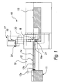
- an apparatus for feeding molten material from the melting area to the holding area in casting apparatuses is generally designated by the reference numeral 10.
- the flow of molten metal 14 between the melting furnace 11 and the channel 12 occurs by means of a pump 12a.
- First level sensors 12b are provided within the channels 12.
- the channel 12 is heated by way of per se known heating means, which are not shown in the figures.
- the pressurizable holding furnace 15 is associated, by way of casting means, for example casting tubes 16, with a die (not shown in the figures).
- the casting tubes 16 have their inlet 16a immersed in the molten metal of the holding furnace 15.
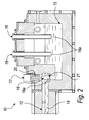
- a closure valve 17 is arranged between the heated channel 12 and the holding furnace 15.
- Such closure valve 17 comprises a flow control element 18, which is associated with a translational actuator 19, which in this embodiment corresponds to a pneumatic cylinder and allows the flow control element 18 to perform a translational motion at right angles to the outflow section of the molten material 14 through said valve.
- the flow control element 18 is connected to the translational actuator 19 by means of a cylindrical stem 20.
- Said outflow section substantially coincides with the sealing seat 21 with which the flow control element 18 mates.
- the sealing seat 21 has a circular cross-section that matches the transverse cross-section of the part 18a of the flow control element 18 that mates with the seat 21.
- the flow control element 18 can perform a translational motion from a position that is substantially spaced from the sealing seat 21 to a position for mating with the seat 21; in any case, the flow control element 18 remains constantly in contact with the molten metal 14 both when the valve 17 is open and when it is closed.
- the flow control element 18, moreover, is associated with an axial rotation actuator 22, which in this embodiment consists of a pneumatic cylinder that is arranged horizontally and is associated with kinematic means.
- Such kinematic means are constituted, in this embodiment, by spherical joints (not shown in the figures), which act between the cylinder and the flow control element and between the cylinder and the base structure to which it is coupled, and allow to convert the linear motion of the pneumatic cylinder into a circular motion.
- the axial rotation actuator 22 allows the flow control element 18 to rotate about its own stem 20 when it is inserted in the sealing seat 21.
- both the flow control element 18 and the sealing seat 21 are made of ceramic material.
- Such automated opening/closure means are constituted by second level sensors (not shown in the figures) for detecting the level of the molten metal inside the holding furnace 15.
- the second level sensors are functionally connected to an electronic control and actuation unit (not shown in the figures), which in turn is associated with the translational actuators 19 and with the rotational actuators 22.
- the molten material typically a metal alloy, is fed or melted inside the melting furnace 11 and sent to the pressurizable holding furnace 15 along the heated channels 12 by means of the pump 12a, which is managed automatically by the first level sensors 12b.
- the melting furnace 11 feeds the channel 12 by means of the pump 12a and keeps its level constant.
- the flow control element orders the rotational actuator 22 to make the flow control element perform a plurality of partial rotations (for example rotations through approximately 45° alternated in clockwise/counterclockwise directions) while it is mated with the seat 21 with a slight pressure.
- the seat 21 is cleaned and the flow control element settles in an optimum manner on the seat 21.
- the valve is then closed further by increasing the closure pressure of the flow control element 18 on the seat 21.
- the holding furnace 15 is then pressurized and the molten material contained inside it can rise through the casting tubes 16 into the die, which is at a lower pressure, where solidification occurs.
- the air or gas used to pressurize the furnace 15 is discharged and the valve 17 can be reopened.
- the molten material resumes flowing from the channel 12 toward the holding furnace 15, which is thus returned to the level for injection into the die.
- the optimum level inside the channel 12 is maintained by means of the pump 12a and the first level sensors 12b.
- the lower part of the flow control element 18 is always in contact with the molten material, so as to avoid thermal shocks.
- the present invention provides an apparatus for feeding molten material from the melting area to the holding area in casting apparatuses, particularly apparatuses using a low-pressure process, that reduces surface oxidation of the molten material that flows within the closed channels.
- the present invention provides an apparatus for feeding molten material from the melting area to the holding area in casting apparatuses, particularly apparatuses using a low-pressure process, that ensures a constant temperature along the entire path of the molten material.
- the present invention provides an apparatus for feeding molten material from the melting area to the holding area in casting apparatuses, particularly apparatuses using a low-pressure process, that allows to automate the operations for filling the pressurizable holding furnace, allowing a "continuous" feed and thus solving the logistic problems linked to the filling of holding furnaces.
- the molten material is fed to the pressurizable furnace cyclically, without manual interventions, substantially by using the automatic system that actuates the valve that closes the feed between the channel and the holding furnace.
- the present invention provides an apparatus for feeding molten material from the melting area to the holding area in casting apparatuses, particularly apparatuses using a low-pressure process, that eliminates the risks linked to the operations for pouring and transferring the molten metal in said apparatus.
- the materials employed may be any according to requirements and to the state of the art.
Landscapes
- Engineering & Computer Science (AREA)
- Mechanical Engineering (AREA)
- Casting Support Devices, Ladles, And Melt Control Thereby (AREA)
Priority Applications (1)
| Application Number | Priority Date | Filing Date | Title |
|---|---|---|---|
| EP04004683A EP1570930A1 (de) | 2004-03-01 | 2004-03-01 | Giessvorrichtung zur Leitung von Schmelze aus einer Schmelzzone zu einer Warmhaltezone, insbesondere in Niederdruckanlagen |
Applications Claiming Priority (1)
| Application Number | Priority Date | Filing Date | Title |
|---|---|---|---|
| EP04004683A EP1570930A1 (de) | 2004-03-01 | 2004-03-01 | Giessvorrichtung zur Leitung von Schmelze aus einer Schmelzzone zu einer Warmhaltezone, insbesondere in Niederdruckanlagen |
Publications (1)
| Publication Number | Publication Date |
|---|---|
| EP1570930A1 true EP1570930A1 (de) | 2005-09-07 |
Family
ID=34745947
Family Applications (1)
| Application Number | Title | Priority Date | Filing Date |
|---|---|---|---|
| EP04004683A Withdrawn EP1570930A1 (de) | 2004-03-01 | 2004-03-01 | Giessvorrichtung zur Leitung von Schmelze aus einer Schmelzzone zu einer Warmhaltezone, insbesondere in Niederdruckanlagen |
Country Status (1)
| Country | Link |
|---|---|
| EP (1) | EP1570930A1 (de) |
Cited By (3)
| Publication number | Priority date | Publication date | Assignee | Title |
|---|---|---|---|---|
| DE102006040256A1 (de) * | 2006-08-28 | 2008-03-06 | Ing. Rauch Fertigungstechnik Gmbh | Niederdruck-Giessverfahren und Vorrichtung hierfür |
| DE102018001777A1 (de) | 2018-03-06 | 2019-09-12 | Sabrina Maurer | Warmhaltezonen in Küchenarbeitsplatten und Verfahren zu deren Herstellung sowie heizbarer Gegenstand, Steuerung, automatischer Temperaturregelung von Warmhaltezonen in Küchenarbeitsplatten |
| CN110488599A (zh) * | 2019-08-22 | 2019-11-22 | 安徽枫慧金属股份有限公司 | 一种炉膛压力控制系统 |
Citations (4)
| Publication number | Priority date | Publication date | Assignee | Title |
|---|---|---|---|---|
| JPH01202343A (ja) * | 1987-10-14 | 1989-08-15 | Komatsu Ltd | 熱電素子の製造方法 |
| JPH06154992A (ja) * | 1992-11-13 | 1994-06-03 | Kobe Steel Ltd | Mg合金低圧鋳造装置 |
| JPH06328229A (ja) * | 1993-05-25 | 1994-11-29 | Toshiba Mach Co Ltd | 溶湯供給装置 |
| EP0846509A1 (de) * | 1996-12-05 | 1998-06-10 | General Motors Corporation | Zwei-Kammer-Ofen für das Gegenschwerkraft-Giessen |
-
2004
- 2004-03-01 EP EP04004683A patent/EP1570930A1/de not_active Withdrawn
Patent Citations (4)
| Publication number | Priority date | Publication date | Assignee | Title |
|---|---|---|---|---|
| JPH01202343A (ja) * | 1987-10-14 | 1989-08-15 | Komatsu Ltd | 熱電素子の製造方法 |
| JPH06154992A (ja) * | 1992-11-13 | 1994-06-03 | Kobe Steel Ltd | Mg合金低圧鋳造装置 |
| JPH06328229A (ja) * | 1993-05-25 | 1994-11-29 | Toshiba Mach Co Ltd | 溶湯供給装置 |
| EP0846509A1 (de) * | 1996-12-05 | 1998-06-10 | General Motors Corporation | Zwei-Kammer-Ofen für das Gegenschwerkraft-Giessen |
Non-Patent Citations (3)
| Title |
|---|
| PATENT ABSTRACTS OF JAPAN vol. 013, no. 500 (M - 891) 10 November 1989 (1989-11-10) * |
| PATENT ABSTRACTS OF JAPAN vol. 018, no. 472 (M - 1667) 2 September 1994 (1994-09-02) * |
| PATENT ABSTRACTS OF JAPAN vol. 1995, no. 02 31 March 1995 (1995-03-31) * |
Cited By (4)
| Publication number | Priority date | Publication date | Assignee | Title |
|---|---|---|---|---|
| DE102006040256A1 (de) * | 2006-08-28 | 2008-03-06 | Ing. Rauch Fertigungstechnik Gmbh | Niederdruck-Giessverfahren und Vorrichtung hierfür |
| DE102018001777A1 (de) | 2018-03-06 | 2019-09-12 | Sabrina Maurer | Warmhaltezonen in Küchenarbeitsplatten und Verfahren zu deren Herstellung sowie heizbarer Gegenstand, Steuerung, automatischer Temperaturregelung von Warmhaltezonen in Küchenarbeitsplatten |
| CN110488599A (zh) * | 2019-08-22 | 2019-11-22 | 安徽枫慧金属股份有限公司 | 一种炉膛压力控制系统 |
| CN110488599B (zh) * | 2019-08-22 | 2022-03-01 | 安徽枫慧金属股份有限公司 | 一种炉膛压力控制系统 |
Similar Documents
| Publication | Publication Date | Title |
|---|---|---|
| US5657812A (en) | Metal-casting apparatus and method | |
| EP0732980B1 (de) | Gussverfahren und -vorrichtung | |
| EP3603851B1 (de) | Verfahren und vorrichtung zum giessen von gegenständen aus aluminium, aluminiumlegierungen, leichtlegierungen, messing und dergleichen | |
| EP1304184A1 (de) | Verfahren und vorrichtung zum zuführen von flüssigmetall, herstellungsverfahren für geschmolzenes aluminium, verfahren zur herstellung von aluminiumdruckgussteilen, automobilherstellungsverfahren, transportfahrzeug, container und vorrichtung zum zuführen von flüssigmetall | |
| FI82620C (fi) | Maskin foer tryckgjutning foer metalldelar innehaollande eventuellt keramikfibrer. | |
| KR101854968B1 (ko) | 알루미늄 합금용 핫 챔버 주조기 | |
| CN101094740B (zh) | 熔液定量供给用保持炉 | |
| EP1797977A2 (de) | Druckgießen in Feingiessformen | |
| KR100696741B1 (ko) | 경금속 주조품, 특히 마그네슘 및 마그네슘 합금의 부품을 제조하기 위한 방법 및 장치 | |
| JP2010089135A (ja) | 鋳造溶湯保持炉 | |
| AU2009317592B2 (en) | Ladle pipe for liquid metal casting plant | |
| DE19821946A1 (de) | Verfahren und Vorrichtungen zum automatischen Gießen von Bauteilen durch quantifiziertes Füllen eines Raumes mit geschmolzenem Metall | |
| KR101888187B1 (ko) | 이중 챔버 에어 가압 보온로 | |
| JP2009512558A (ja) | ダイカスト方法及びダイカスト装置 | |
| CZ20012649A3 (cs) | Způsob odlévání a zařízení k provádění tohoto způsobu | |
| US10695827B2 (en) | Light metal injection molding machine | |
| EP2425913A1 (de) | Verbesserte Vorrichtung zum Einfüllen von Metallschmelze in die Formen von Druckgussmaschinen | |
| KR101132930B1 (ko) | 용탕 정량 공급용 유지로 | |
| CA2770823C (en) | Pour ladle for molten metal | |
| JPH11192541A (ja) | アルミニウム合金の鋳造装置 | |
| JP2008044008A (ja) | 低圧鋳造装置および不活性ガスの充満方法 | |
| US20260008096A1 (en) | Method of tapping molten metal and apparatus for tapping molten metal | |
| CN110740826B (zh) | 分离滑阀系统,浇铸设备和浇铸方法 | |
| CN113751696A (zh) | 用于压铸机的铸造单元 | |
| JP7824669B2 (ja) | 出湯方法および出湯設備 |
Legal Events
| Date | Code | Title | Description |
|---|---|---|---|
| PUAI | Public reference made under article 153(3) epc to a published international application that has entered the european phase |
Free format text: ORIGINAL CODE: 0009012 |
|
| AK | Designated contracting states |
Kind code of ref document: A1 Designated state(s): AT BE BG CH CY CZ DE DK EE ES FI FR GB GR HU IE IT LI LU MC NL PL PT RO SE SI SK TR |
|
| AX | Request for extension of the european patent |
Extension state: AL LT LV MK |
|
| 17P | Request for examination filed |
Effective date: 20060220 |
|
| AKX | Designation fees paid |
Designated state(s): AT BE BG CH CY CZ DE DK EE ES FI FR GB GR HU IE IT LI LU MC NL PL PT RO SE SI SK TR |
|
| RAP1 | Party data changed (applicant data changed or rights of an application transferred) |
Owner name: TEKSID ALUMINIUM S.P.A Owner name: IDRA S.R.L. |
|
| GRAP | Despatch of communication of intention to grant a patent |
Free format text: ORIGINAL CODE: EPIDOSNIGR1 |
|
| STAA | Information on the status of an ep patent application or granted ep patent |
Free format text: STATUS: THE APPLICATION IS DEEMED TO BE WITHDRAWN |
|
| 18D | Application deemed to be withdrawn |
Effective date: 20071005 |