EP1570965A2 - Table de fraisage - Google Patents
Table de fraisage Download PDFInfo
- Publication number
- EP1570965A2 EP1570965A2 EP05101604A EP05101604A EP1570965A2 EP 1570965 A2 EP1570965 A2 EP 1570965A2 EP 05101604 A EP05101604 A EP 05101604A EP 05101604 A EP05101604 A EP 05101604A EP 1570965 A2 EP1570965 A2 EP 1570965A2
- Authority
- EP
- European Patent Office
- Prior art keywords
- particular according
- spring element
- work plate
- milling table
- spring
- Prior art date
- Legal status (The legal status is an assumption and is not a legal conclusion. Google has not performed a legal analysis and makes no representation as to the accuracy of the status listed.)
- Granted
Links
Images


Classifications
-
- B—PERFORMING OPERATIONS; TRANSPORTING
- B27—WORKING OR PRESERVING WOOD OR SIMILAR MATERIAL; NAILING OR STAPLING MACHINES IN GENERAL
- B27C—PLANING, DRILLING, MILLING, TURNING OR UNIVERSAL MACHINES FOR WOOD OR SIMILAR MATERIAL
- B27C5/00—Machines designed for producing special profiles or shaped work, e.g. by rotary cutters; Equipment therefor
- B27C5/02—Machines with table
- B27C5/06—Arrangements for clamping or feeding work
-
- B—PERFORMING OPERATIONS; TRANSPORTING
- B27—WORKING OR PRESERVING WOOD OR SIMILAR MATERIAL; NAILING OR STAPLING MACHINES IN GENERAL
- B27C—PLANING, DRILLING, MILLING, TURNING OR UNIVERSAL MACHINES FOR WOOD OR SIMILAR MATERIAL
- B27C5/00—Machines designed for producing special profiles or shaped work, e.g. by rotary cutters; Equipment therefor
- B27C5/10—Portable hand-operated wood-milling machines; Routers
Definitions
- the invention initially relates to a milling table with a work plate, the one Opening for the passage of the milling cutter has, from one at the bottom the work plate fastened drive machine especially in the form of a Router is drivable, with a mounting flange of the drive machine by means arranged on the underside of the work plate centering laterally position fixable and clamped by means of claws against the bottom, which Claws are each secured by a clamping pin on the worksheet.
- a milling table has a work plate.
- the work plate is a Opening.
- On the underside of the worksheet is a drive machine.
- the Drive machine has a drive shaft. On the drive shaft sits Feed.
- a cutter such as a milling cutter is held. This protrudes through the opening of the work plate.
- the bottom can the work plate provided with a support frame, for example with support legs be.
- On the top of the work plate is a stop on which the workpiece is feasible. This, in a horizontal direction on the Work plate guided sliding and in the displacement positions fixable stop is also called a rip fence.
- the Work plate can still be a transverse, so parallel to the stop running Have leadership in which there may be another stop.
- Parallel stop spring elements can be attached, as for example from US 2002 / 0,162,439 A1 are known. These spring elements serve the Hold down the workpiece against the work plate.
- a T-slot may be provided, in which a sliding block rests, with its Help the spring element can be attached to the rip fence.
- the But spring element can also in the other, possibly also as a T-slot trained guide groove of the worksheet be arranged to go through its spring force a pressure effect of the workpiece against the Generate rip fence.
- the prime mover which is attached to the underside of the worksheet, can be a router.
- This router has a mounting flange, which has a essentially circular or circle-like outline contour having.
- the end face of this mounting flange is against the Bottom of the work plate or against the bottom of a lower side Recess of the work plate pressed. For this serve Spannpratzen.
- the lateral Position is fixed by means of centering organs. These attack at three or four Circumferential locations on the mounting flange. In the mounting position is the Mounting flange in contact with this centering device.
- the invention is based on the object, a generic milling table or accessories for this purpose benefit further training.
- Claim 1 initially and essentially provides that the Centering is a centering disc with eccentric opening. By the Opening of a claw carrying a claw protrudes.
- the bottom of the Centering disc can be slightly spaced from the underside of the worktop be.
- a direct installation of the centering disc on the underside of the work plate is preferably only in the immediate vicinity of the eccentric Opening given.
- the centering disc can have a circular outline contour exhibit.
- Within the centering a nut can be arranged so that the centering disc with the clamping pin, which has an external thread may have, can be screwed. With a mother can under Forming a counter-nut effect, the centering on the spigot be attached.
- the clamping pin rotates in an opening of the work plate rests, so that by rotation of the Clamping the clamping effect can be achieved. Then it serves Centering disc not only the lateral position fixation of the drive machine, but also the rotational fixation of the clamping pin.
- the clamping claw can a Be plastic part.
- On this pressure piece can be a knurled or toggle nut acting on is screwed on the chuck.
- circular cylindrical support shoulder supports the claw on the bottom of the Recess or on the underside of the work plate.
- the other arm of the Pratze presses on the mounting flange of the prime mover.
- the clamping pin in plug connection stands with the retaining plate. He has for this purpose a cone-shaped end portion, which rests in a corresponding reduction in the retaining plate.
- the reduction can be generated by bending and has a lateral recess, in which protrudes from the conical surface of the end portion of the clamping pin Nose for rotation can occur.
- the attachment of the clamping pin to the work plate has its own Importance.
- the top of the worksheet may be pot-like depressions have, in which plate-shaped holding discs eino.
- the back of the Retaining washers has a threaded flange.
- the threaded flange protrudes into one Through hole. In the threaded flange is the chuck screwed.
- the invention further relates to a milling table with a work plate and a arranged on the work plate longitudinal stop, which in a first horizontal direction on the worksheet guided displaceable Stop jaw carrier has, which stop jaw carrier two mutually displaceable and lockable in the transfer points Stop jaws having, in a second horizontal direction aligned T-shaped guide groove for receiving a sliding block, on which a perpendicular to the worksplate extension plane Spring element is fastened.
- the stop jaws are releasably attached to the stop jaw carrier.
- fastening means in particular in the form of a clamping screw and a Clamping nut screwed onto the clamping screw.
- Clamping screw / nut can be the stop jaw along a support surface of the stop jaw carrier are displaced in the horizontal direction.
- the two Clamping jaws can thus be shifted towards each other.
- the distance of Both jaws can, according to this displacement on the Diameter of the respective milling cutter can be adjusted.
- the router is located in the space between the two stop jaws.
- the invention provides that the walls of the guide groove that the recording serve the sliding block, on the one hand from the stop bracket and on the other hand be formed by the stop jaw.
- the Support surface of the jaw carrier on which the stop jaw in Horizontal direction displaceable and fixable against displaceability L-shaped be configured.
- the L-leg forms the one, also L-shaped Wall of the T-slot.
- the opposite of this wall Wall is formed by a narrow longitudinal edge of the stop jaw.
- This T-slot is the sliding block, which carries the spring element.
- the invention further relates to a spring element for a milling table or the like, as is known in particular from US 2002 / 0,162,439 A1.
- the previously known spring element is expensive. It has several, comb-like arranged spring bars.
- the spring element has a circumferentially closed Leaf spring.
- This leaf spring may have a substantially elliptical shape , wherein the large semiaxis of the ellipse is preferably more than twice as long as the small half-axis of the ellipse. That's the leaf spring having spring element may consist of plastic.
- the spring element also has a support body. This has a longitudinal slot. By the Longitudinal slot can protrude the shaft of a clamping screw or a clamping pin, which interacts with the sliding block.
- the leaf spring integrally attached to the support body.
- the thus configured spring element can as Injection molded part are manufactured.
- the support body is preferably in the field of formed semi-minor axis of the ellipse of the leaf spring.
- the longitudinal slot can then lie in aligned extension to the small half-axis.
- Adjustment aid is used in the area of the narrow ends of the elliptical spring attached stage.
- the vertical position of the spring element to the work plate or also the distance position of the spring element for rip fence can help be set to this level. It is based on the thickness or width of the Workpiece set. Since the slightly curved belly of the leaf spring over protrudes this abutment surface, the leaf spring under shortening the small semi-axis when moving the workpiece clamped.
- the stage can be formed by a kink of the spring. But it is also possible, the stage to train from a hump.
- a reinforcing plate Metal lies on the bottom of the recess. Since the material thickness of the work plate in the area of the recess is reduced, this reinforcing plate ensures an increase in stability. Due to the reduced material thickness, the reinforcing plate is at the edge the depression attached. This essentially forms the shape of a four-leaf clover forming reinforcing plate fastening tabs out. They are preferably two diametrically opposite ones Fixing tabs provided, forming a right angle protrude from the edge of the reinforcing plate. With their overhanging edge Sections is the reinforcing plate with a section of the edge of the Screwed recess.
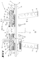
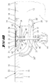
- the invention relates to a milling table 1.
- This has a horizontal Work plate 2. From the bottom 4 of the work plate 2 project obliquely L-shaped Leg 9 from whose free ends, each with a foot cap 10 made of rubber are provided.
- the bottom 4 has at its two longitudinal edge sides respectively an angle rail 14, which serves for stabilization.
- At the front Angle rail 14 is also a housing 11 for a switch.
- a recess 16 which has a parallel to the bottom 4 extending bottom 15 forms. Following this depression 16 the material thickness of the work plate 2 is reduced in the central area.
- a circular opening 22 Approximately in the middle of a rounded wall having recess 16 there is a circular opening 22. In the embodiments inserted in the opening 22, a reducer 18, the edge of a stage 19th such that the surface of the reducer 18 with the top 23rd the work plate 2 is aligned. In the center, this has a circular floor plan having reducer 18 an opening 20 through which a router over the top 23 can protrude.
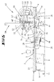
- the cutter not shown in the figures belongs to a ground 15 of the Deepening 16 attachable router 12.
- the router 12 which is shown in phantom in the figures, has one at the end of the milling cutter, and only in the drawings dash-dotted attachment flange 13.
- This mounting flange 13 may have a substantially circular floor plan.
- centering discs 28 are provided on the floor 15
- the recess 16 is a total of four centering 28th
- the centering discs 28 have a cup-shaped shape. They are circular and have an eccentric opening 29.
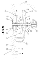
- each recess 39 brought in.
- the retaining plate 40 has a backward one Threaded flange 41.
- this threaded flange 41 is a threaded pin 27th screwed. This forms a clamping pin.
- the clamping pin 27 can screwed into the threaded flange 41 section also there be glued.
- the holding plate 40 is covered by a plastic cap 21, whose Top to the top 23 of the work plate 2 is flush.
- the clamping pin 27 extends through the eccentric opening 29 of the centering 28, which rests directly on the nut 31. Under interposition of a another washer 42 acts a clamping nut 30 against the Centering disk 28. When the clamping nut 30 is loosened, the centering disk 28 to be pivoted about the clamping pin 27. By tightening the Clamping nut 30, the pivotal position of the centering disc 28 with respect to the clamping pin 27 are fixed.
- a toggle 44th screwed On the free end of the clamping pin 27 is a toggle 44th screwed. An intermediate portion of the clamping pin 27 passes through a Longitudinal slot 27 of a clamping claw 26. The pointing to the toggle nut 44 Back of the clamping claw 26 forms a corrugated pressure edge 34. On this corrugated pressure edge 24 is supported by the chuck 27th penetrated pressure piece 45 from, against which interposition of a another washer 25, the toggle 44 acts.
- the clamping pin 27 is thus simultaneously bearing pin of the centering pulley 28th and the clamping claw 26.
- An end portion 26 'of the clamping claw 26 presses on the mounting flange thirteenth the router 12.
- the other end portion 26 'of the clamping claw 26 forms a rounded support shoulder 37, located on the bottom 15 of the recess 16th supported.
- the accessed by the clamping pin 27 longitudinal slot 17 of Clamp 26 is slightly offset eccentrically to the end 26 'between the both ends 26 ', 26 "of the clamping claw 26.
- the clamping claw 26 is as well as the toggle nut 44 made of plastic.
- the holding plate 40 has pointed projections 62 which dig into the bottom of the recess 39 can to rotationally fix the retaining disk 40.
- the retaining plate 40 has in Center a depression 33 formed by an expression 33.
- a conical end portion 32 of the clamping pin 27 In the subsidence 33 superimposed a conical end portion 32 of the clamping pin 27. From the conical End portion 32 of the clamping pin 27 protrudes laterally a nose 35. This nose 35th engages in a recess 36 of the countersink 33, so that the clamping pin 27th is rotationally secured. Otherwise, the clamping pin, as well as in the in FIG. 6 illustrated embodiment of a nut 31 against the work plate. 2 held.
- This guide slot 5 On the upper side 23 of the work plate 2 is a longitudinal direction (Y direction) extending guide slot 5.
- This guide slot 5 has a T-shaped Profile.
- a sliding block can glide, which an angle stop 3 is assigned.
- the angle stop 3 can by means of a Clamping nut 6 are fixed in its angular position. He can be within the Guide slot 5 are moved in the Y direction.
- a clamping nut 58 holds a further described below Spring element 54 also in the guide slot 5.
- the clamping nut 58th fixes the spring element 54 in both the X and Y directions.
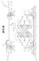
- guide grooves 7 are spaced apart. Also store in these guide grooves 7 Sliding blocks that interact with clamping nuts 61. By tightening the clamping nuts 61, a stop bracket 48 are fixed in position. When loosening clamping nuts 61, the stop jaw carrier 48 in the X direction be moved. Its distance to the router can thereby be set.
- the stop jaw carrier 48 forms a substantially perpendicular to Top 23 extending support surface 55 from. On this support surface 55 store two stop jaws 51.
- the stop jaws 51 can in the direction of Y. be shifted towards each other.
- a pull piece 56 which is designed as a carriage bolt, a longitudinal slot 49. This allows the Distance between the two facing each other narrow edges 51 "of Stop jaws 51 on the diameter of the milling cutter, not shown be set.
- the cutter is located below a finger guard 8 between the two stop jaws 51st
- a Clamping nut 59 On the back 57 of the jaw carrier 58 is a Clamping nut 59 which is screwed onto the pulling piece 56.
- Clamping nut 59 By means of Clamping nut 59, the position of the stop jaw 51 can be fixed.
- the Longitudinal gussets 51 'of the stop jaw 51 have an L-shaped configuration. Inside is an L-shaped portion 48 'of the stop jaw carrier opposite.
- the L-shaped portion 48 'and the narrow edge 51' together form a T-shaped Guiding 52 for a sliding block 53 from.
- a spring element 54 At this Sliding block 53 is a spring element 54 fixed. This is done by means of a Clamping nut 60.
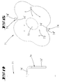
- the above-mentioned spring elements 54 on the one hand form a hold-down, which presses the workpiece against the top 23 of the work plate 2, and on the other side a horizontal pressure piece, the workpiece against the Stop jaws 48 presses.
- the spring elements 54 have the following described shape:
- the spring element 54 consists of a plastic part. It has an elongated support body 46 which has a longitudinal slot 56. With the help of the slot 56, the spring element 54 on the work plate 2 or attached to the stop jaw carrier 48. For this purpose, a clamping screw passes through or the like, the slot 56th
- At one end of the support body 64 is an elliptical leaf spring 63 formed.
- the belly 69 has a large radius.
- the two Narrowing of the leaf spring 66 have a small radius.
- the step 67 may by a kink 68 of the end portion of the leaf spring 63rd be formed. But it is also envisaged that in this area Leaf spring 63 forms a step 67, which on the top of the workpiece can be hung up.
- the belly 69 of the leaf spring 63 can escape in the direction of the support body 64.
- the Elasticity of the leaf spring 63 then provides the necessary contact pressure on the one hand against the top 23 of the work plate 2 and on the other hand against the Stop jaw 51.
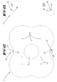
- Fig. 12 shows a reinforcing plate 71, which in the recess 16 of Bottom 4 of the work plate 2 can be used.
- the reinforcing plate 71 has a substantially cloverleaf contour outline, made of steel and has in the middle of an opening 72, the opening of the work plate 2, the Reducer accommodates 18, is congruent. Furthermore are located in the Reinforcement plate 71 mounting holes 73, which also for the passage of the Chuck 27 are suitable.
- the outline contour of the reinforcing plate 71 corresponds to the outline contour of they receive recess 16 so that the reinforcing plate 71 on the Floor 15 of the recess 16 can be placed. This will be the opposite the rest of the work plate 2 material-reduced bottom 15 reinforced.
- the Attachment of the reinforcing plate 71 is preferably carried out with the Deepening 16 surrounding edge of the bottom 4. For this purpose are at the Reinforcing plate 71 substantially at right angles projecting Mounting straps 74 provided. In the embodiment has the Reinforcing plate 71 in each case in the region of two opposing Constrictions a fastening tab 74.
- the directly from the edge of the Reinforcing plate 71 protruding leg 74 'of the fastening tab 74 has a length corresponding to the depth of the recess 16.
- the one from this thigh 74 'right-angled mounting leg 74' has a Mounting hole through which screwed a mounting screw can be, with the fastening tab 74 with the edge region of Well 16 can be attached.
- the clamping pins 27 project through Openings 73 of the reinforcing plate 71, so that in Fig. 6 recognizable washer 38 directly on the reinforcing plate can support.
- the designated by the reference numeral 19 in Fig. 9 stage can be formed from the edge of the opening 72, so that the reducer 18 itself can be supported on the edge of the opening 72.
Landscapes
- Life Sciences & Earth Sciences (AREA)
- Engineering & Computer Science (AREA)
- Mechanical Engineering (AREA)
- Wood Science & Technology (AREA)
- Forests & Forestry (AREA)
- Jigs For Machine Tools (AREA)
- Milling, Drilling, And Turning Of Wood (AREA)
- Milling Processes (AREA)
- Springs (AREA)
Applications Claiming Priority (4)
| Application Number | Priority Date | Filing Date | Title |
|---|---|---|---|
| DE102004010735 | 2004-03-05 | ||
| DE102004010735 | 2004-03-05 | ||
| DE102005009227 | 2005-02-25 | ||
| DE102005009227.6A DE102005009227B4 (de) | 2004-03-05 | 2005-02-25 | Frästisch und Zubehör |
Publications (3)
| Publication Number | Publication Date |
|---|---|
| EP1570965A2 true EP1570965A2 (fr) | 2005-09-07 |
| EP1570965A3 EP1570965A3 (fr) | 2005-12-14 |
| EP1570965B1 EP1570965B1 (fr) | 2007-09-26 |
Family
ID=34751406
Family Applications (1)
| Application Number | Title | Priority Date | Filing Date |
|---|---|---|---|
| EP05101604A Expired - Lifetime EP1570965B1 (fr) | 2004-03-05 | 2005-03-02 | Elément de ressort pour une table de fraisage |
Country Status (4)
| Country | Link |
|---|---|
| US (1) | US20050230003A1 (fr) |
| EP (1) | EP1570965B1 (fr) |
| CA (1) | CA2499716A1 (fr) |
| DE (2) | DE102005009227B4 (fr) |
Cited By (1)
| Publication number | Priority date | Publication date | Assignee | Title |
|---|---|---|---|---|
| CN110802513A (zh) * | 2019-10-18 | 2020-02-18 | 安徽涌诚机械有限公司 | 高性能涡轮增压器的压气机壳用夹具 |
Families Citing this family (11)
| Publication number | Priority date | Publication date | Assignee | Title |
|---|---|---|---|---|
| US7409973B2 (en) * | 2004-08-25 | 2008-08-12 | Lee Valley Tools Ltd. | Router table plate assembly |
| DE102007011784A1 (de) * | 2006-06-30 | 2008-01-03 | Wolfcraft Gmbh | Arbeitstisch, insbesondere Frästisch mit in einer Einsatzöffnung einer Arbeitsplatte einsetzbarer Einsatzplatte |
| CN102501274B (zh) * | 2011-12-08 | 2014-11-12 | 东莞市长丰木工机械设备有限公司 | 一种木材曲面加工用数控铣床 |
| USD781677S1 (en) | 2015-06-16 | 2017-03-21 | Lee Valley Tools Ltd. | Tool holder |
| CN108481463B (zh) * | 2018-04-08 | 2020-04-17 | 高唐县新华木业有限公司 | 一种板材快速切割装置的工作方法 |
| CN109227486A (zh) * | 2018-11-22 | 2019-01-18 | 张旭 | 一种木材锯切固定设备 |
| CN111230536B (zh) * | 2020-02-12 | 2021-07-06 | 江苏金沃伺服冲床有限公司 | 一种机床用自动触发式定位机构及其使用方法 |
| CN114516098B (zh) * | 2020-11-18 | 2025-09-16 | 南京泉峰科技有限公司 | 一种动力设备 |
| CN112589489B (zh) * | 2020-12-11 | 2021-11-09 | 衢州学院 | 一种可调节方向的多功能机械加工夹具及其使用方法 |
| CN112599047A (zh) * | 2020-12-29 | 2021-04-02 | 淄博职业学院 | 一种工商管理教学用智能宣传板 |
| CN113021277B (zh) * | 2021-03-02 | 2022-03-22 | 黄山耀瑞精密模塑科技有限公司 | 一种精密模具生产加工用夹紧装置 |
Family Cites Families (68)
| Publication number | Priority date | Publication date | Assignee | Title |
|---|---|---|---|---|
| US404233A (en) * | 1889-05-28 | Saw-table gage | ||
| US727337A (en) * | 1902-10-02 | 1903-05-05 | Jacob A Conrey | Guide for woodworking-machines. |
| US1183566A (en) * | 1914-09-04 | 1916-05-16 | Louis Branch | Safety-guard for shapers. |
| US1664969A (en) * | 1927-01-08 | 1928-04-03 | John C Conover | Guide for molder tables |
| US1715722A (en) * | 1927-11-23 | 1929-06-04 | Thomas S Smith | Door-supporting vise |
| DE878096C (de) * | 1951-05-03 | 1953-06-01 | Karl Schaeff | Tischfraese mit zwei Fraesspindeln |
| US3101104A (en) * | 1961-03-29 | 1963-08-20 | Weyerhaeuser Co | Safety device for saws |
| US3723927A (en) * | 1969-05-05 | 1973-03-27 | Gen Dynamics Corp | Magnetic holding means in a surface plate dimensional measuring apparatus |
| US3944203A (en) * | 1973-11-30 | 1976-03-16 | Brekelbaum Erwin C | Oxidation cutting work support means |
| US3905273A (en) * | 1974-07-22 | 1975-09-16 | Shyodu Precision Instr Company | Machine tool assembly |
| US4114665A (en) * | 1976-05-06 | 1978-09-19 | Decker Henry P | Woodworking bench for portable motor driven hand tools |
| USD248304S (en) * | 1976-09-03 | 1978-06-27 | Vermont American Corporation | Table for portable cutting tools |
| US4088164A (en) * | 1977-06-02 | 1978-05-09 | Vermont American Corporation | Portable router attachment |
| US4132256A (en) * | 1977-06-22 | 1979-01-02 | Jones John C | Guide for cutting apparatus |
| US4186784A (en) * | 1977-07-21 | 1980-02-05 | Atlantic Container Corporation | Tool table construction |
| USD273195S (en) * | 1981-08-14 | 1984-03-27 | Hirsh Company | Power tool table |
| US4445553A (en) * | 1981-12-10 | 1984-05-01 | Hanyzewski Eugene F | Apparatus for shaping a wooden workpiece |
| US4738571A (en) * | 1982-09-29 | 1988-04-19 | Olson Eugene T | Routing apparatus with dust extraction system |
| US4484608A (en) * | 1982-10-21 | 1984-11-27 | Hirsh Company | Router table |
| US4603612A (en) * | 1984-12-17 | 1986-08-05 | Atkins Richard R | Safety attachment for a table saw |
| US4615247A (en) * | 1985-09-13 | 1986-10-07 | Shopsmith, Inc. | Anti-kickback system |
| US4719951A (en) * | 1986-02-10 | 1988-01-19 | Woltanski Joseph W | Combination drill press, router and shaper table, and methods of constructing and utilizing same |
| US4750536A (en) * | 1986-04-30 | 1988-06-14 | Grisley Kenneth M | Router vacuum attachment |
| US4688510A (en) * | 1986-08-14 | 1987-08-25 | Mcneely Fay C | Place marker |
| US4763706A (en) * | 1987-04-13 | 1988-08-16 | Verle L. Rice | Router mounting table |
| US5046645A (en) * | 1988-02-19 | 1991-09-10 | Mckesson Corporation | Syphon package with mechanically attached valve |
| US5016358A (en) * | 1988-05-06 | 1991-05-21 | Rice Verle L | Guide fence and mitre guide assembly for router mounting table |
| US4884604A (en) * | 1988-05-06 | 1989-12-05 | Verle L. Rice | Guide fence and mitre guide assembly for router mounting table |
| US4977938A (en) * | 1989-05-16 | 1990-12-18 | Greeson Ewell E | Cutting guide for portable router |
| US5026033A (en) * | 1989-11-22 | 1991-06-25 | The Budd Company | Universal system for the support and positioning of a workpiece |
| US5367933A (en) * | 1990-03-14 | 1994-11-29 | Jaksha; Jerome F. | Power tool shield and guiding apparatus |
| DE9003963U1 (de) * | 1990-04-05 | 1990-06-07 | B & M Blumenbecker GmbH, 4720 Beckum | Vorrichtung zum Andrücken eines Werkstückes auf einen Tisch einer Fräsmaschine |
| US5024257A (en) * | 1990-04-18 | 1991-06-18 | Lloyd James E | Woodworking machine |
| US5000237A (en) * | 1990-06-25 | 1991-03-19 | Shopsmith, Inc. | Jointer cutter guard with featherboard |
| US5025841A (en) * | 1990-07-12 | 1991-06-25 | Porta-Nails, Inc. | Multi-purpose support table for a router |
| US5107599A (en) * | 1990-08-28 | 1992-04-28 | General Motors Corporation | Universal fixture for coordinate measuring machines |
| US5042542A (en) * | 1990-09-06 | 1991-08-27 | Purviance John R | Router table gauge |
| USD334388S (en) * | 1990-10-16 | 1993-03-30 | Delta International Machinery Corp. | Combination bench router and shaper |
| US5117880A (en) * | 1990-10-16 | 1992-06-02 | Delta International Machinery Corporation | Shield for cutting blade |
| US5139065A (en) * | 1991-12-03 | 1992-08-18 | Stark I Bruce | Auxiliary drop-in table top power tool base |
| US5148846A (en) * | 1992-02-03 | 1992-09-22 | Harry Van Gelder | Workpiece guide |
| USD343846S (en) * | 1992-03-18 | 1994-02-01 | Woodstock International, Inc. | Router table |
| US5289861A (en) * | 1992-03-23 | 1994-03-01 | Hedrick David G | Multi-purpose quick-change work surface platform for use with power tools |
| US5333657A (en) * | 1992-10-13 | 1994-08-02 | Larry Hart | Workpiece turing and milling apparatus |
| US5398740A (en) * | 1993-11-12 | 1995-03-21 | Miller; Manford B. | Power tool table with adjustable tool mounting plate insert and related method |
| CA2150066A1 (fr) * | 1994-07-08 | 1996-01-09 | Andrew L. Itzov | Support reglable pour piece a usiner de scie a onglet combinee |
| US5452751A (en) * | 1994-07-18 | 1995-09-26 | Engler, Iii; Nicholas A. | Multi-purpose router baseplate |
| DE4429570C1 (de) * | 1994-08-19 | 1996-02-29 | Scheppach Maschf J | Holzbearbeitungsmaschine |
| US5809631A (en) * | 1994-12-19 | 1998-09-22 | Poulin; Jean-Paul | Multiple-axis machining apparatus |
| US5755148A (en) * | 1995-07-07 | 1998-05-26 | Black & Decker Inc. | Adjustable fence for a compound miter saw |
| US5611378A (en) * | 1996-01-19 | 1997-03-18 | Ryobi North America | Tilting router table |
| US5779407A (en) * | 1996-02-01 | 1998-07-14 | Lee Valley Tools Ltd. | Router table fence system |
| US5725038A (en) * | 1996-08-29 | 1998-03-10 | Lee Valley Tools Ltd. | Router baseplate and table |
| US5755319A (en) * | 1996-09-03 | 1998-05-26 | Credo Tool Company | Safety power switch |
| US5699844A (en) * | 1996-10-22 | 1997-12-23 | Witt; Bradley R. | Router plate with removable inserts |
| US5855234A (en) * | 1997-07-14 | 1999-01-05 | Ryobi North America Inc. | Router table assembly with microset throat plate |
| US5868188A (en) * | 1997-10-31 | 1999-02-09 | Fukuda, Inc. | Method, system and apparatus for safely cutting a workpiece on an inverted router table |
| FR2774581B1 (fr) * | 1998-02-10 | 2000-08-11 | Dimso Sa | Stabilisateur interepineux a fixer a des apophyses epineuses de deux vertebres |
| US6170372B1 (en) * | 1998-12-21 | 2001-01-09 | Richard A. Weaver | Dual spring hold down for wood working tools |
| US6234056B1 (en) * | 1999-06-25 | 2001-05-22 | Harvey Raymond Oslick | Reciprocating resaw |
| CA2278869A1 (fr) * | 1999-07-27 | 2001-01-27 | Darrin Eugene Smith | Dispositif de reglage de niveau pour outil mecanique |
| US20020162439A1 (en) | 2000-02-02 | 2002-11-07 | Bench Dog, Inc. | Workpiece motion guide and method |
| US6237658B1 (en) * | 2000-04-20 | 2001-05-29 | Glen E. Hylton | Workpiece guide apparatus for wood routers, shapers and the like |
| US6360798B1 (en) | 2000-08-11 | 2002-03-26 | Wolfcraft Gmbh | Router tables |
| US6382276B1 (en) * | 2001-05-22 | 2002-05-07 | Wolfcraft, Inc. | Router table adapter base plate |
| US6792984B2 (en) * | 2001-06-19 | 2004-09-21 | Bench Dog, Inc. | Router lift |
| US6779954B2 (en) * | 2002-07-03 | 2004-08-24 | Black & Decker, Inc. | Router depth of cut adjustment |
| DE20219977U1 (de) * | 2002-12-24 | 2003-03-13 | Lin, Deng-Ke, Feng-Yuan, Taichung | Optimierung der Konstruktion einer Drehhobelbank |
-
2005
- 2005-02-25 DE DE102005009227.6A patent/DE102005009227B4/de not_active Expired - Lifetime
- 2005-03-02 EP EP05101604A patent/EP1570965B1/fr not_active Expired - Lifetime
- 2005-03-02 DE DE502005001550T patent/DE502005001550D1/de not_active Expired - Lifetime
- 2005-03-03 US US11/073,318 patent/US20050230003A1/en not_active Abandoned
- 2005-03-07 CA CA002499716A patent/CA2499716A1/fr not_active Abandoned
Cited By (2)
| Publication number | Priority date | Publication date | Assignee | Title |
|---|---|---|---|---|
| CN110802513A (zh) * | 2019-10-18 | 2020-02-18 | 安徽涌诚机械有限公司 | 高性能涡轮增压器的压气机壳用夹具 |
| CN110802513B (zh) * | 2019-10-18 | 2021-12-24 | 安徽涌诚机械有限公司 | 高性能涡轮增压器的压气机壳用夹具 |
Also Published As
| Publication number | Publication date |
|---|---|
| CA2499716A1 (fr) | 2005-09-05 |
| DE502005001550D1 (de) | 2007-11-08 |
| EP1570965A3 (fr) | 2005-12-14 |
| US20050230003A1 (en) | 2005-10-20 |
| DE102005009227B4 (de) | 2023-06-15 |
| DE102005009227A1 (de) | 2005-09-29 |
| EP1570965B1 (fr) | 2007-09-26 |
Similar Documents
| Publication | Publication Date | Title |
|---|---|---|
| DE69319849T2 (de) | Sägeblatt-Spannfutter | |
| EP0332096B1 (fr) | Table avec dispositif de liaison | |
| DE1627012C3 (de) | Bohrkopf o.dgl. Werkzeughalter | |
| CH625315A5 (fr) | ||
| DE4236049A1 (de) | C-förmige Zwinge | |
| EP3138674B1 (fr) | Dispositif de coupe en onglet | |
| EP1570965A2 (fr) | Table de fraisage | |
| DE4037649A1 (de) | Entgratwerkzeug | |
| WO1993005937A1 (fr) | Dispositif de protection et de guidage pour fraiseuses a bois___ | |
| EP1857223B1 (fr) | Actionnement par oscillation doté d'une butée de profondeur et butée de profondeur pour un actionnement par oscillation | |
| EP1995024A1 (fr) | Appareil de travail manuel | |
| WO1994003311A1 (fr) | Tete porte-lames, en particulier tete porte-lames a profiler | |
| EP0684099A1 (fr) | Outil combiné | |
| DE2722256B2 (fr) | ||
| EP0459121A2 (fr) | Sabot de guidage pour machine portative | |
| WO2015185396A1 (fr) | Dispositif de fixation servant à fixer un objet sur une paroi et système de fixation | |
| CH690357A5 (de) | Rohranfasgerät. | |
| AT527418A4 (de) | Scharnierbohrlehre zur Herstellung eines Bohrbildes für Scharniere in einer Möbelplatte | |
| DE102006012079A1 (de) | Befestigungsvorrichtung für eine Handfräse an einem Frästisch | |
| DE4025440A1 (de) | Tischsaege | |
| DE1477355A1 (de) | Werkzeughalter fuer Schneidwerkzeuge | |
| DE202004012350U1 (de) | Verbindungsbeschlag für Platten, insbesondere für Tablare | |
| DE933860C (de) | Wasserpumpenzange | |
| DE3304206A1 (de) | Schneidwerkzeug und halter | |
| EP1308379B1 (fr) | Support pivotable et réglable en direction longitudinal pour une partie pivotable de carrosserie, en particulier capot de coffre à bagages |
Legal Events
| Date | Code | Title | Description |
|---|---|---|---|
| PUAI | Public reference made under article 153(3) epc to a published international application that has entered the european phase |
Free format text: ORIGINAL CODE: 0009012 |
|
| AK | Designated contracting states |
Kind code of ref document: A2 Designated state(s): AT BE BG CH CY CZ DE DK EE ES FI FR GB GR HU IE IS IT LI LT LU MC NL PL PT RO SE SI SK TR |
|
| AX | Request for extension of the european patent |
Extension state: AL BA HR LV MK YU |
|
| PUAL | Search report despatched |
Free format text: ORIGINAL CODE: 0009013 |
|
| RIC1 | Information provided on ipc code assigned before grant |
Ipc: 7B 27C 5/02 A Ipc: 7B 23C 1/00 B Ipc: 7B 27C 5/06 B Ipc: 7B 23Q 3/00 B Ipc: 7B 27B 27/00 B |
|
| AK | Designated contracting states |
Kind code of ref document: A3 Designated state(s): AT BE BG CH CY CZ DE DK EE ES FI FR GB GR HU IE IS IT LI LT LU MC NL PL PT RO SE SI SK TR |
|
| AX | Request for extension of the european patent |
Extension state: AL BA HR LV MK YU |
|
| 17P | Request for examination filed |
Effective date: 20060502 |
|
| 17Q | First examination report despatched |
Effective date: 20060704 |
|
| AKX | Designation fees paid |
Designated state(s): DE FR GB |
|
| 17Q | First examination report despatched |
Effective date: 20060704 |
|
| GRAP | Despatch of communication of intention to grant a patent |
Free format text: ORIGINAL CODE: EPIDOSNIGR1 |
|
| RTI1 | Title (correction) |
Free format text: SPRING ELEMENT FOR A MILLING TABLE |
|
| RIN1 | Information on inventor provided before grant (corrected) |
Inventor name: RADERMACHER, UWE |
|
| GRAS | Grant fee paid |
Free format text: ORIGINAL CODE: EPIDOSNIGR3 |
|
| GRAA | (expected) grant |
Free format text: ORIGINAL CODE: 0009210 |
|
| REG | Reference to a national code |
Ref country code: DE Ref legal event code: R081 Ref document number: 502005001550 Country of ref document: DE Owner name: WOLFCRAFT GMBH, DE Free format text: FORMER OWNER: WOLFCRAFT GMBH, 56746 KEMPENICH, DE |
|
| AK | Designated contracting states |
Kind code of ref document: B1 Designated state(s): DE FR GB |
|
| REG | Reference to a national code |
Ref country code: GB Ref legal event code: FG4D Free format text: NOT ENGLISH |
|
| REF | Corresponds to: |
Ref document number: 502005001550 Country of ref document: DE Date of ref document: 20071108 Kind code of ref document: P |
|
| REG | Reference to a national code |
Ref country code: DE Ref legal event code: R096 Ref document number: 502005001550 Country of ref document: DE Effective date: 20071108 |
|
| ET | Fr: translation filed | ||
| GBT | Gb: translation of ep patent filed (gb section 77(6)(a)/1977) |
Effective date: 20071219 |
|
| PGFP | Annual fee paid to national office [announced via postgrant information from national office to epo] |
Ref country code: FR Payment date: 20080305 Year of fee payment: 4 |
|
| PLBE | No opposition filed within time limit |
Free format text: ORIGINAL CODE: 0009261 |
|
| STAA | Information on the status of an ep patent application or granted ep patent |
Free format text: STATUS: NO OPPOSITION FILED WITHIN TIME LIMIT |
|
| 26N | No opposition filed |
Effective date: 20080627 |
|
| REG | Reference to a national code |
Ref country code: DE Ref legal event code: R097 Ref document number: 502005001550 Country of ref document: DE Effective date: 20080627 |
|
| PGFP | Annual fee paid to national office [announced via postgrant information from national office to epo] |
Ref country code: GB Payment date: 20090316 Year of fee payment: 5 |
|
| REG | Reference to a national code |
Ref country code: FR Ref legal event code: ST Effective date: 20091130 |
|
| PG25 | Lapsed in a contracting state [announced via postgrant information from national office to epo] |
Ref country code: FR Free format text: LAPSE BECAUSE OF NON-PAYMENT OF DUE FEES Effective date: 20091123 |
|
| GBPC | Gb: european patent ceased through non-payment of renewal fee |
Effective date: 20100302 |
|
| PG25 | Lapsed in a contracting state [announced via postgrant information from national office to epo] |
Ref country code: GB Free format text: LAPSE BECAUSE OF NON-PAYMENT OF DUE FEES Effective date: 20100302 |
|
| PGFP | Annual fee paid to national office [announced via postgrant information from national office to epo] |
Ref country code: DE Payment date: 20230323 Year of fee payment: 19 |
|
| P01 | Opt-out of the competence of the unified patent court (upc) registered |
Effective date: 20230513 |
|
| REG | Reference to a national code |
Ref country code: DE Ref legal event code: R119 Ref document number: 502005001550 Country of ref document: DE |
|
| PG25 | Lapsed in a contracting state [announced via postgrant information from national office to epo] |
Ref country code: DE Free format text: LAPSE BECAUSE OF NON-PAYMENT OF DUE FEES Effective date: 20241001 |
|
| PG25 | Lapsed in a contracting state [announced via postgrant information from national office to epo] |
Ref country code: DE Free format text: LAPSE BECAUSE OF NON-PAYMENT OF DUE FEES Effective date: 20241001 |