EP1570972A1 - Thermoformmaschine mit Zwischenspeicher und Verfahren zum Betreiben selbiger - Google Patents
Thermoformmaschine mit Zwischenspeicher und Verfahren zum Betreiben selbiger Download PDFInfo
- Publication number
- EP1570972A1 EP1570972A1 EP05003006A EP05003006A EP1570972A1 EP 1570972 A1 EP1570972 A1 EP 1570972A1 EP 05003006 A EP05003006 A EP 05003006A EP 05003006 A EP05003006 A EP 05003006A EP 1570972 A1 EP1570972 A1 EP 1570972A1
- Authority
- EP
- European Patent Office
- Prior art keywords
- stacking
- tool
- catch plate
- article
- thermoforming machine
- Prior art date
- Legal status (The legal status is an assumption and is not a legal conclusion. Google has not performed a legal analysis and makes no representation as to the accuracy of the status listed.)
- Granted
Links
- 238000003856 thermoforming Methods 0.000 title claims abstract description 38
- 238000000034 method Methods 0.000 title claims description 29
- 230000001360 synchronised effect Effects 0.000 claims abstract description 5
- 230000001133 acceleration Effects 0.000 claims description 12
- 239000004033 plastic Substances 0.000 claims description 6
- 238000004519 manufacturing process Methods 0.000 claims description 3
- 238000012546 transfer Methods 0.000 abstract description 9
- 230000015572 biosynthetic process Effects 0.000 description 3
- 238000005755 formation reaction Methods 0.000 description 3
- 230000032258 transport Effects 0.000 description 3
- 230000001934 delay Effects 0.000 description 2
- 238000013461 design Methods 0.000 description 2
- 238000006073 displacement reaction Methods 0.000 description 2
- 239000002985 plastic film Substances 0.000 description 2
- 229920006255 plastic film Polymers 0.000 description 2
- 230000003068 static effect Effects 0.000 description 2
- 241000881711 Acipenser sturio Species 0.000 description 1
- 230000002411 adverse Effects 0.000 description 1
- 230000000295 complement effect Effects 0.000 description 1
- 230000035622 drinking Effects 0.000 description 1
- 230000000694 effects Effects 0.000 description 1
- 238000009957 hemming Methods 0.000 description 1
- 230000002452 interceptive effect Effects 0.000 description 1
- 235000013310 margarine Nutrition 0.000 description 1
- 239000003264 margarine Substances 0.000 description 1
- 239000000463 material Substances 0.000 description 1
- 238000000465 moulding Methods 0.000 description 1
- 238000007639 printing Methods 0.000 description 1
- 238000012545 processing Methods 0.000 description 1
- 238000007493 shaping process Methods 0.000 description 1
- GOLXNESZZPUPJE-UHFFFAOYSA-N spiromesifen Chemical compound CC1=CC(C)=CC(C)=C1C(C(O1)=O)=C(OC(=O)CC(C)(C)C)C11CCCC1 GOLXNESZZPUPJE-UHFFFAOYSA-N 0.000 description 1
- 229920001169 thermoplastic Polymers 0.000 description 1
- 239000004416 thermosoftening plastic Substances 0.000 description 1
- 238000013519 translation Methods 0.000 description 1
- 238000004804 winding Methods 0.000 description 1
Images

Classifications
-
- B—PERFORMING OPERATIONS; TRANSPORTING
- B29—WORKING OF PLASTICS; WORKING OF SUBSTANCES IN A PLASTIC STATE IN GENERAL
- B29C—SHAPING OR JOINING OF PLASTICS; SHAPING OF MATERIAL IN A PLASTIC STATE, NOT OTHERWISE PROVIDED FOR; AFTER-TREATMENT OF THE SHAPED PRODUCTS, e.g. REPAIRING
- B29C51/00—Shaping by thermoforming, i.e. shaping sheets or sheet like preforms after heating, e.g. shaping sheets in matched moulds or by deep-drawing; Apparatus therefor
- B29C51/26—Component parts, details or accessories; Auxiliary operations
- B29C51/44—Removing or ejecting moulded articles
-
- B—PERFORMING OPERATIONS; TRANSPORTING
- B65—CONVEYING; PACKING; STORING; HANDLING THIN OR FILAMENTARY MATERIAL
- B65G—TRANSPORT OR STORAGE DEVICES, e.g. CONVEYORS FOR LOADING OR TIPPING, SHOP CONVEYOR SYSTEMS OR PNEUMATIC TUBE CONVEYORS
- B65G57/00—Stacking of articles
- B65G57/02—Stacking of articles by adding to the top of the stack
- B65G57/16—Stacking of articles of particular shape
- B65G57/165—Stacking of articles of particular shape nested
Definitions
- the invention relates to a method for operating a thermoforming machine for molding of stackable articles of plastic, in which in a tool manufactured articles with a demolding element removed from the tool and a downstream stacking and counting device are supplied, wherein the Stacking and counting a catch plate, by means of the removal of the manufactured Article of the thermoforming machine takes place, as well as a stacking basket for Recording stacked items before their removal from the stacking and counting device having. Furthermore, the invention relates to a thermoforming machine with a downstream stacking and counting device.
- thermoforming machine of the generic type Art A method of operating a thermoforming machine of the generic type Art is known from DE 198 48 628 C2.
- plastic articles for example Margarine bowls, drinking cup, container lid
- thermoplastic films and laminated films produced. It will be in the closed position of the tool consisting of upper and lower tools, the articles are shaped, then punched and then with the position of the tool out of this out and fed into a downstream stacking and counting device.
- the Upper part of the tool of the machine is mounted on a rigid cross-bridge; However, the lower part of the tool is designed to be vertically movable and pivotable. To accomplish the pivoting of the lower tool part has this one journal whose bearing in a vertically guided guide piece is arranged.
- thermoforming machine During the stacking of fabricated articles from the thermoforming machine into the Stacking and counting device is the lower part of the tool, d. H. it will no stroke and no pivoting movement executed. After the stacking process the lower tool part is swung back into the vertical position and vertically return to the position in which it is with the upper part of the tool interacts. It is known to operate the thermoforming machine so that for the delivery and the driving away of the catch plate and for moving the vertically movable and pivoting tool part a synchronization movement takes place in order to keep the cycle time of the machine as low as possible. Basically, the aim is that the cycle times for the process of Tool lower parts, so for its translation and pivoting movement, as well the catch plate and the Entformelements are as low as possible, the output power to maximize the facility.
- thermoforming machine with downstream Stacking and counting device which has a catch plate, wherein at this Article holding means are provided, which are formed as retaining springs and with such a pitch are spaced apart, wherein the stacked Item added loosely between complementary recesses of the retaining springs is.
- the catch plate behind their finished article receiving formations for each article bar connect two parallel spaced stacking rods in the area of the head end of a finished article ejected from the machine with spring-loaded Stack hinges are provided.
- both mentioned solutions can largely dispensed with holding elements for the article stack, which This is why it is advantageous because they cause problems when removing the stack and in principle can lead to deformations of the still somewhat soft article.
- thermoforming machine passes from the thermoforming machine to the stacking and counting device which are located in the stacking magazines or in the catch plate Stack after stacking an article taking this article with you by means of a separate from the transfer device displacement device by a measure greater than or equal to the distance between the is stacked containers. Also, it should be achieved that when passing of articles in stack magazines or in a catch plate no risk of deformation for the articles by shifting the already formed stack by the stacking dimension given is.
- a significant influence on the stack formation has the machine-related Entformanselement (ejector system) through which the molded articles are transported from the tool in the delivered catch plate of the stacking and counting device. Because of the desired output of the thermoforming machine, a small travel time of the Entformelements is sought, with traversing speeds of 2 m / s and accelerations or decelerations of 20 m / s 2 are not uncommon. However, these process parameters have the following disadvantages, in particular in the case of flat containers, covers, etc.
- the stacking pulses cause a falling apart or slipping apart the stack of articles, especially at the beginning of the stack. To this effect too reduce to the corresponding holding elements (see the above-described Solutions in the prior art) clamping elements used. Especially in thin-walled articles, however, consists of the Einapelimpulse the Risk of deformation of the last and previously stacked article.
- thermoforming machine with downstream Stacking and counting device have therefore coincidentally the disadvantageous Characteristics that the stacking of the manufactured articles under considerable Mass forces takes place, which adversely affects the process reliability of the process. Smaller stacking speeds, with lower mass forces would go along, forbid due to economic considerations, the demand a fast movement of the manufactured articles.
- the invention is therefore based on the object, a method for operating a Thermoforming machine with downstream stacking and counting device as well to create such a thermoforming machine, which is that of the prior art has no longer known disadvantages.
- the solution of this problem by the invention is according to the method characterized that the catch plate made in the tool an intermediate buffer, in particular a single intermediate buffer, in which one Number of stacked items to be accumulated, and one in the intermediate buffer desired number of stacked articles intermittently from the intermediate buffer into the Stacking basket is spent or transported.
- the catch plate in each case only in a single Production cycle of the thermoforming machine manufactured article the intermediate buffer supplies.
- a continuing education provides that before removing the article from the tool a part of the tool, in particular a lower tool part, to a predetermined Angle is pivoted in one of the catch plate delivered position. After that comes the method described with pivoting tool lower part for use. It is provided with advantage that the movement of Catch plate for the opening and closing movement of the tool as well as for Pivoting movement of one part of the tool is synchronized as it is as such is known in the art.
- the movement of the catch plate of the tool assigned Position to the intermediate buffer assigned position of two movement sections consists of different, preferably in each case constant, Accelerations or delays are marked.
- thermoforming machine with a downstream stacking and counting device for shaping and transporting stackable articles made of plastic is so configured such that the thermoforming machine has a tool that with a Entformelement is provided for manufactured articles from the tool; the Stacking and counting device has a catch plate, with the finished article can be removed from the thermoforming machine, and a stacking basket, which is suitable for receiving a number of stacked articles.
- this thermoforming machine is characterized by an intermediate buffer, in particular through a single intermediate buffer, for taking a number stacked article arranged between catch plate and stacking basket.
- the intermediate buffer is arranged stationary, and there are moving means present, with which the catch plate and the stacking basket moves translationally can be.
- the catch plate, the intermediate buffer and the stacking basket are advantageous arranged a linear path.
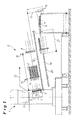
- thermoforming machine 1 In Fig. 1, a thermoforming machine 1 is shown, from the (left) side a plastic film strip 13 is fed to the inlet side, the outlet side according to the registered arrow rewound on a winding roll, not shown becomes.
- the thermoforming machine 1 is a wheeled, automatic Stacking and counting device 6 and this in turn a conveyor belt 14th downstream.
- the thermoforming machine 1 has a tool 3, 4, which is formed in two parts is and from a stationary upper tool part 3 and a exists relative to this movable tool part 4. As explained above, this is movable tool part 4 translational relative to the fixed tool part. 3 movable and otherwise pivotally arranged in the open tool position, to accomplish the demoulding of Article 2 and those of the downstream ones Supply stacking and counting device 6.
- Fig. 1 the open Tool 3, 4 shown with the pivoted movable tool wedge 4.
- the stacking and counting device 6 has a movable catch plate 7, in accordance with the number of movable tool part 4 of the machine. 1 in over- and adjacent rows of mold cavities provided a corresponding Number of tool cavities, in which the article 2 of a only very schematically shown Entformelement 5 discharged or ejected and then stacked into stacked article poles.
- the stacking and counting device 6 further comprises a stacking basket 8, which the Stakes stacked article 2 picks up and from which the article poles then be delivered to the conveyor belt 14. From there you can get one further processing operation are supplied, for. B. a printing machine or a hemming unit.
- the stacking basket 8 is for removing the article rods in the direction of the catch plate. 7 towards a transfer position 15 movable. After the takeover of the article poles the stacking basket 8 can then be in an unloading station remote from the catching plate 7 16 are moved. The stacking basket 8 can out of this position 16 are lowered intermittently, first with a large Senkhub 17 so far, until the bottom row of the article poles in flight with a Abschiebeech 18, and then each with a height 19 of the superimposed Rows of article poles corresponding hub.
- the deportation unit 18, which has a pusher bar 20 for each article bar and toward of the double arrow 21 is movable back and forth, pushes the successive partial strokes lowered article rods on the conveyor belt 14 via.
- the transfer takes place in the Thermoforming machine 1 manufactured article 2 of the catch plate 7 in the stacking basket 8 not directly, but via an intermediate buffer 9.
- the procedure is that after performing a process cycle in the Thermoforming machine 1, the just-made Article 2 of the Entformelement 5 at pivoted movable tool part 4 from the tool 3, 4 deported and be taken over by the catch plate 7.
- the catch plate 7 transports the Article 2 of this single machine cycle to the intermediate buffer 9 and puts them there until a desired number of stacked articles 2 is in the intermediate buffer 9.
- the stacking basket 8 moves to the transfer position 15 and takes over the article poles for further handling such as explained.
- While both the catch plate 7 and the stacking basket 8 by not shown Moving means are movable along a linear path 12, which is Intermediate buffer 9 arranged stationary relative to the stacking and counting device 6. This can be achieved that the stacking of the individual articles 2 by the Catch plate 7 takes place in the intermediate buffer 9 with very small mass forces, so that a quasi-static stacking can take place. This will increase the process stability of the process significantly increased and the articles to be handled are treated very gently. This is especially important if to achieve the lowest possible cycle time the still warm and To handle something soft Article 2 or this formed very thin-walled are.
- the positioned at the end of the travel of the catch plate 7 intermediate buffer 9th takes over each transported by the catch plate 7 Article 2 a production cycle the thermoforming machine 1.
- the intermediate buffer 9 is arranged stationary and is therefore not exposed to any movement. Thus, the stacking can be static respectively.
- the catch plate 7 has a lengthened by a factor of 8 travel what, for the bridging of the interference circuit of the pivotable tool part 4 would be required. This makes it possible, on the one hand, that the required high accelerations and speeds within the interference circuit On the other hand, after leaving the interference circuit the remaining travel used to the high traversing speed decelerate with a small, constant delay.
- the delay is in in each case so small that the mass forces generated from it on the article 2 smaller than the frictional force between the edge of the article and the article overlay.
- Fig. 2 are various movements of the thermoforming machine 1 and the Parts of the downstream stacking and counting device 6 shown over time, where a complete process cycle is shown.
- Fig. 2a first shows how the movable tool part 4 moves.
- the tool 3, 4 is closed, d. H. the movable tool part 4 is in contact with the stationary tool part 3.
- the article 2 is manufactured in the tool 3, 4, and the movable tool part 4 begins to lower down.
- Fig. 2b begins shortly after the lowering movement of the movable tool part 4 (at time 23), the pivoting movement of the Tool part 4 in the position shown in Fig. 1. This is present as soon as the Tilt angle 24 is reached.
- the Entformelement 5 (see Fig. 1) is actuated, whereby the Article 2 are ejected from the tool part 4.
- the course of the hub of the Entformelements 5 over time is shown in FIG. 2c.
- the catch plate 7 during the pivoting movement of the Tool part 4 is not located in the Stör Schl, by the pivoting movement of this part is defined. That is why it is basically necessary that the catch plate 7 is moved with a velocity profile, as shown in Fig. 2d is indicated. Ie. that the catch plate 7 - as soon as it is the pivoting position of Tool part 4 allowed - is accelerated in the direction tool, then on the tool part 4 is moved to remove the article 2 from the tool part 4. When this is done, the catch plate 7 transports the removed articles 2 in the direction of intermediate buffer 9, to which the second marked with crossed lines Speed course is needed.
- Fig. 2e an optimized speed profile for the catch plate 7 is outlined. There it can be seen that the movement of the catch plate 7 from two movement sections 10 and 11, wherein the moving portion 10 by a lower acceleration (less steep course) in relation to the movement section 11 distinguished. Thereafter, the catch plate 7 during the left Movement section 10 accelerates slowly towards the movable tool part 4 and strongly decelerated during the left movement section 11 until it comes to rest in the removal position on the tool part 4. The articles 2 are grabbed here and the catch plate 7 then with relatively high acceleration according to the right movement section 11 in the direction of intermediate buffer 9 accelerates.
- the proposed constant acceleration or deceleration according to Movement sections 10 and 11 proves to be advantageous because on the article 2 during the Einstapeins in the intermediate buffer 9 no forces acting, a falling apart of the pile. Due to the relatively long braking distance the catch plate 7 is the speed of the catch plate 7 during the stacking in the intermediate buffer 9 only a fraction of the speed of the otherwise standard stacking drive.
- thermoforming machine 1 is thus characterized by a separate stacking drive for the stack formation by means of the catch plate 7, which from the Entformelement. 5 (Machine ejector) is decoupled.
- the explained traversing dynamics of the stacking drive, d. H. the catch plate 7, leads to the advantages described.
Landscapes
- Engineering & Computer Science (AREA)
- Mechanical Engineering (AREA)
- Blow-Moulding Or Thermoforming Of Plastics Or The Like (AREA)
Abstract
Description
- Fig. 1
- schematisch in der Seitenansicht eine Thermoformmaschine mit nachgeschalteter Stapel- und Zählvorrichtung für abzustapelnde Becher;
- Fig. 2a
- den Verlauf des Hubs des beweglichen Werkzeugteils über der Zeit;
- Fig. 2b
- den Verlauf des Kippwinkels des beweglichen Werkzeugteils über der Zeit;
- Fig. 2c
- den Verlauf des Hubs des Entformelements (Werkzeug-Auswerfer) über der Zeit;
- Fig. 2d
- den Verlauf der Geschwindigkeit der Fangplatte über der Zeit gemäß einer ersten Möglichkeit; und
- Fig. 2e
- den Verlauf der Geschwindigkeit der Fangplatte über der Zeit gemäß einer verbesserten Möglichkeit.
- 1
- Thermoformmaschine
- 2
- stapelfähiger Artikel
- 3, 4
- Werkzeug
- 3
- ortsfestes Werkzeugteil
- 4
- bewegliches Werkzeugteil
- 5
- Entformelement
- 6
- Stapel- und Zählvorrichtung
- 7
- Fangplatte
- 8
- Stapelkorb
- 9
- Zwischenpuffer
- 10
- Bewegungsabschnitt
- 11
- Bewegungsabschnitt
- 12
- lineare Bahn
- 13
- Kunststoff-Folienband
- 14
- Transportband
- 15
- Übergabeposition
- 16
- Entladestation
- 17
- Senkhub
- 18
- Abschiebeeinheit
- 19
- Höhenmaß
- 20
- Abschieberstab
- 21
- Doppelpfeil
- 22
- Hub
- 23
- Zeitpunkt
- 24
- Kippwinkel
Claims (9)
- Verfahren zum Betreiben einer Thermoformmaschine (1) zum Formen von stapelfähigen Artikeln (2) aus Kunststoff, bei dem in einem Werkzeug (3, 4) gefertigte Artikel (2) mit einem Entformelement (5) aus dem Werkzeug (3, 4) entfernt und einer nachgeschalteten Stapel- und Zählvorrichtung (6) zugeführt werden, wobei die Stapel- und Zählvorrichtung (6) eine Fangplatte (7), mittels der der Abtransport der gefertigten Artikel (2) von der Thermoformmaschine (1) erfolgt, sowie einen Stapelkorb (8) zur Aufnahme gestapelter Artikel (2) vor deren Abtransport aus der Stapel- und Zählvorrichtung (6) aufweist,
dadurch gekennzeichnet, dass die Fangplatte (7) im Werkzeug (3, 4) gefertigte Artikel (2) einem Zwischenpuffer (9) zuführt, in dem eine Anzahl gestapelter Artikel (2) angesammelt wird, und dass eine im Zwischenpuffer (9) gewünschte Anzahl gestapelter Artikel (2) intermittierend vom Zwischenpuffer (9) in den Stapelkorb (8) verbracht wird. - Verfahren nach Anspruch 1,
dadurch gekennzeichnet, dass die Fangplatte (7) jeweils nur die in einem einzigen Fertigungszyklus der Thermoformmaschine (1) hergestellten Artikel (2) dem Zwischenpuffer (9) zuführt. - Verfahren nach Anspruch 1 oder 2,
dadurch gekennzeichnet, dass vor dem Entfernen des Artikels (2) aus dem Werkzeug (3, 4) ein Teil (4) des Werkzeugs (3, 4), insbesondere ein Unterwerkzeugteil, um einen vorgegebenen Winkel in eine der Fangplatte (7) zugestellte Position geschwenkt wird. - Verfahren nach Anspruch 3,
dadurch gekennzeichnet, dass die Bewegung der Fangplatte (7) zur Öffnungs- und Schließhubbewegung des Werkzeugs (3, 4) sowie zur Schwenkbewegung des einen Teils (4) des Werkzeugs (3, 4) synchronisiert erfolgt. - Verfahren nach einem der Ansprüche 1 bis 4,
dadurch gekennzeichnet, dass die Bewegung der Fangplatte (7) von der dem Werkzeug (3, 4) zugeordneten Position zu der dem Zwischenpuffer (9) zugeordneten Position in zwei Bewegungsabschnitte (10, 11) mit unterschiedlichen Beschleunigungen oder Verzögerungen unterteilt wird. - Verfahren nach Anspruch 5,
dadurch gekennzeichnet, dass die beiden Bewegungsabschnitte (10, 11) der Fangplatte (7) jeweils mit einer konstanten Beschleunigung oder Verzögerung durchfahren werden. - Thermoformmaschine (1) mit einer nachgeschalteten Stapel- und Zählvorrichtung (6) zum Formen und Abtransportieren von stapelfähigen Artikeln (2) aus Kunststoff, wobei die Thermoformmaschine (1) ein Werkzeug (3, 4) aufweist, das mit einem Entformelement (5) für gefertigte Artikel (2) aus dem Werkzeug (3, 4) versehen ist, und wobei die Stapel- und Zählvorrichtung (6) eine Fangplatte (7), mit der gefertigte Artikel (2) aus der Thermoformmaschine (1) abgeführt werden können, sowie einen Stapelkorb (8), der zur Aufnahme einer Anzahl gestapelter Artikel (2) geeignet ist, aufweist,
gekennzeichnet durch
einen Zwischenpuffer (9) für die Aufnahme einer Anzahl gestapelter Artikel (2), der zwischen Fangplatte (7) und Stapelkorb (8) angeordnet ist. - Thermoformmaschine nach Anspruch 7,
dadurch gekennzeichnet, dass der Zwischenpuffer (9) ortsfest angeordnet ist und Bewegungsmittel zur translatorischen Bewegung von Fangplatte (7) und Stapelkorb (8) vorhanden sind. - Thermoformmaschine nach Anspruch 7 oder 8,
dadurch gekennzeichnet, dass die Fangplatte (7), der Zwischenpuffer (9) und der Stapelkorb (8) auf einer linearen Bahn (12) angeordnet sind.
Applications Claiming Priority (2)
| Application Number | Priority Date | Filing Date | Title |
|---|---|---|---|
| DE102004011002 | 2004-03-06 | ||
| DE102004011002A DE102004011002A1 (de) | 2004-03-06 | 2004-03-06 | Verfahren zum Betreiben einer Thermoformmaschine und Thermoformmaschine |
Publications (2)
| Publication Number | Publication Date |
|---|---|
| EP1570972A1 true EP1570972A1 (de) | 2005-09-07 |
| EP1570972B1 EP1570972B1 (de) | 2007-03-28 |
Family
ID=34745421
Family Applications (1)
| Application Number | Title | Priority Date | Filing Date |
|---|---|---|---|
| EP05003006A Revoked EP1570972B1 (de) | 2004-03-06 | 2005-02-12 | Thermoformmaschine mit Zwischenspeicher und Verfahren zum Betreiben selbiger |
Country Status (3)
| Country | Link |
|---|---|
| EP (1) | EP1570972B1 (de) |
| AT (1) | ATE358011T1 (de) |
| DE (2) | DE102004011002A1 (de) |
Cited By (1)
| Publication number | Priority date | Publication date | Assignee | Title |
|---|---|---|---|---|
| EP2100835A1 (de) | 2008-03-11 | 2009-09-16 | Amut S.p.A. | Maschine und Verfahren zum Stapeln thermogeformter Gegenstände |
Families Citing this family (1)
| Publication number | Priority date | Publication date | Assignee | Title |
|---|---|---|---|---|
| ATE555892T1 (de) | 2009-05-14 | 2012-05-15 | Gabler Thermoform Gmbh & Co Kg | Vorrichtung zum stapeln von fertigartikeln aus thermoplastischem kunststoff |
Citations (4)
| Publication number | Priority date | Publication date | Assignee | Title |
|---|---|---|---|---|
| DE3346628A1 (de) * | 1983-12-23 | 1985-07-11 | Adolf Illig Maschinenbau Gmbh & Co, 7100 Heilbronn | Vorrichtung zum formen, stanzen und stapeln von teilen aus thermoplastischer kunststoffolie |
| EP0995581A2 (de) * | 1998-10-22 | 2000-04-26 | Gabler Maschinenbau GmbH | Thermoformmaschine |
| EP1000887A1 (de) * | 1998-11-13 | 2000-05-17 | Illig, Adolf Maschinenbau GmbH & Co. | Vorrichtung zum Aufnehmen und Stapeln von Behältern aus thermoplastischem Kunststoff |
| DE10256141A1 (de) * | 2002-06-21 | 2004-02-05 | Walter Lauermann | Formlings-Stapelsystem mit Gegenhalt |
Family Cites Families (1)
| Publication number | Priority date | Publication date | Assignee | Title |
|---|---|---|---|---|
| DE10052759C2 (de) * | 2000-10-25 | 2002-11-07 | Illig Maschinenbau Adolf | Vorrichtung zum Stapeln von Teilen aus thermoplastischem Kunststoff |
-
2004
- 2004-03-06 DE DE102004011002A patent/DE102004011002A1/de not_active Withdrawn
-
2005
- 2005-02-12 EP EP05003006A patent/EP1570972B1/de not_active Revoked
- 2005-02-12 DE DE502005000509T patent/DE502005000509D1/de not_active Revoked
- 2005-02-12 AT AT05003006T patent/ATE358011T1/de active
Patent Citations (4)
| Publication number | Priority date | Publication date | Assignee | Title |
|---|---|---|---|---|
| DE3346628A1 (de) * | 1983-12-23 | 1985-07-11 | Adolf Illig Maschinenbau Gmbh & Co, 7100 Heilbronn | Vorrichtung zum formen, stanzen und stapeln von teilen aus thermoplastischer kunststoffolie |
| EP0995581A2 (de) * | 1998-10-22 | 2000-04-26 | Gabler Maschinenbau GmbH | Thermoformmaschine |
| EP1000887A1 (de) * | 1998-11-13 | 2000-05-17 | Illig, Adolf Maschinenbau GmbH & Co. | Vorrichtung zum Aufnehmen und Stapeln von Behältern aus thermoplastischem Kunststoff |
| DE10256141A1 (de) * | 2002-06-21 | 2004-02-05 | Walter Lauermann | Formlings-Stapelsystem mit Gegenhalt |
Cited By (1)
| Publication number | Priority date | Publication date | Assignee | Title |
|---|---|---|---|---|
| EP2100835A1 (de) | 2008-03-11 | 2009-09-16 | Amut S.p.A. | Maschine und Verfahren zum Stapeln thermogeformter Gegenstände |
Also Published As
| Publication number | Publication date |
|---|---|
| ATE358011T1 (de) | 2007-04-15 |
| DE102004011002A1 (de) | 2005-09-22 |
| DE502005000509D1 (de) | 2007-05-10 |
| EP1570972B1 (de) | 2007-03-28 |
Similar Documents
| Publication | Publication Date | Title |
|---|---|---|
| DE9219137U1 (de) | Thermoformmaschine zum Herstellen von hohlen Gegenständen | |
| DE19727749C2 (de) | Seitlich einfahrender Roboter zur Entnahme von geformten Gegenständen | |
| DE2534819A1 (de) | Vorrichtung zum entstapeln und transportieren von platinen | |
| CH457268A (de) | Vorrichtung zum Ablegen flächenhafter Gegenstände zu einem Stapel | |
| DE2537279A1 (de) | Palettenentlader | |
| DE102013108231A1 (de) | Verfahren und Vorrichtung zum Stapeln und/oder Palettieren von Gebinde- oder Stückgutlagen | |
| DE3625841A1 (de) | Stapelvorrichtung fuer, insbesondere in einer thermoform-maschine hergestellte, kunststoff-tiefziehteile | |
| DE69605971T2 (de) | Verfahren und automatisierte Vorrichtung zum Verdichten von Produkten zur Verpackung | |
| DE3139828C2 (de) | ||
| EP0995582B1 (de) | Thermoformmaschine | |
| DE3878645T2 (de) | Verfahren und vorrichtung fuer das stapeln von artikeln und das zufuehren der stapel an einen abfuhrbereich. | |
| DE19848628C2 (de) | Verfahren zum Betreiben einer Thermoformmaschine | |
| DE2845676C2 (de) | Vorrichtung zum selbsttätigen Schichten von lamellierten Eisenkernen | |
| DE69513666T2 (de) | Herstellung von spritzgegossenen artikeln mit inbegriffener folie | |
| EP0591099B1 (de) | Verfahren und Vorrichtung zur Herstellung gebundener Stapel von Erzeugnissen aus Papier | |
| DE19509057C2 (de) | Vorrichtung zum Überführen und Stapeln von aus einer thermoplastischen Kunststoffolie tiefgezogenen und ausgestanzten Behältern | |
| EP1570972B1 (de) | Thermoformmaschine mit Zwischenspeicher und Verfahren zum Betreiben selbiger | |
| DE2618950A1 (de) | Plattentransportmaschine | |
| DE102010035670A1 (de) | Hochgeschwindigkeitsspeicher | |
| DE2648563C2 (de) | Vorrichtung zum Stapeln von flachen Tiefziehteilen aus thermoplastischem Kunststoff | |
| DE102017102913A1 (de) | Vorrichtung und Verfahren zur flexiblen Verteilung von Verpackungen | |
| DE3822363C2 (de) | ||
| EP1075923A1 (de) | Verfahren zum Stapeln von Behältern aus thermoplastischem Kunststoff und Vorrichtung zur Durchführung des Verfahrens | |
| DE69505598T2 (de) | Vorrichtung zum Sortieren und Stapeln von flachen Gegenständen in schachtelartigen Behältern | |
| EP1752400A2 (de) | Verfahren zum Überführen von Behälterstapeln zu einer Nachfolgeeinrichtung und Vorrichtung zur Durchführung des Verfahrens |
Legal Events
| Date | Code | Title | Description |
|---|---|---|---|
| PUAI | Public reference made under article 153(3) epc to a published international application that has entered the european phase |
Free format text: ORIGINAL CODE: 0009012 |
|
| AK | Designated contracting states |
Kind code of ref document: A1 Designated state(s): AT BE BG CH CY CZ DE DK EE ES FI FR GB GR HU IE IS IT LI LT LU MC NL PL PT RO SE SI SK TR |
|
| AX | Request for extension of the european patent |
Extension state: AL BA HR LV MK YU |
|
| GRAP | Despatch of communication of intention to grant a patent |
Free format text: ORIGINAL CODE: EPIDOSNIGR1 |
|
| 17P | Request for examination filed |
Effective date: 20060302 |
|
| AKX | Designation fees paid |
Designated state(s): AT DE IT NL |
|
| GRAS | Grant fee paid |
Free format text: ORIGINAL CODE: EPIDOSNIGR3 |
|
| GRAA | (expected) grant |
Free format text: ORIGINAL CODE: 0009210 |
|
| AK | Designated contracting states |
Kind code of ref document: B1 Designated state(s): AT DE IT NL |
|
| REF | Corresponds to: |
Ref document number: 502005000509 Country of ref document: DE Date of ref document: 20070510 Kind code of ref document: P |
|
| PLBI | Opposition filed |
Free format text: ORIGINAL CODE: 0009260 |
|
| PLAX | Notice of opposition and request to file observation + time limit sent |
Free format text: ORIGINAL CODE: EPIDOSNOBS2 |
|
| 26 | Opposition filed |
Opponent name: ADOLF ILLIG MASCHINENBAU GMBH & CO. KG Effective date: 20071220 |
|
| NLR1 | Nl: opposition has been filed with the epo |
Opponent name: ADOLF ILLIG MASCHINENBAU GMBH & CO. KG |
|
| PLAF | Information modified related to communication of a notice of opposition and request to file observations + time limit |
Free format text: ORIGINAL CODE: EPIDOSCOBS2 |
|
| PLAF | Information modified related to communication of a notice of opposition and request to file observations + time limit |
Free format text: ORIGINAL CODE: EPIDOSCOBS2 |
|
| PLBB | Reply of patent proprietor to notice(s) of opposition received |
Free format text: ORIGINAL CODE: EPIDOSNOBS3 |
|
| PGFP | Annual fee paid to national office [announced via postgrant information from national office to epo] |
Ref country code: IT Payment date: 20100219 Year of fee payment: 6 |
|
| RDAF | Communication despatched that patent is revoked |
Free format text: ORIGINAL CODE: EPIDOSNREV1 |
|
| PGFP | Annual fee paid to national office [announced via postgrant information from national office to epo] |
Ref country code: AT Payment date: 20100212 Year of fee payment: 6 Ref country code: DE Payment date: 20100219 Year of fee payment: 6 |
|
| PGFP | Annual fee paid to national office [announced via postgrant information from national office to epo] |
Ref country code: NL Payment date: 20100215 Year of fee payment: 6 |
|
| RDAG | Patent revoked |
Free format text: ORIGINAL CODE: 0009271 |
|
| STAA | Information on the status of an ep patent application or granted ep patent |
Free format text: STATUS: PATENT REVOKED |
|
| 27W | Patent revoked |
Effective date: 20100710 |