EP1571008A2 - Modulare Achsanordnung - Google Patents
Modulare Achsanordnung Download PDFInfo
- Publication number
- EP1571008A2 EP1571008A2 EP04027542A EP04027542A EP1571008A2 EP 1571008 A2 EP1571008 A2 EP 1571008A2 EP 04027542 A EP04027542 A EP 04027542A EP 04027542 A EP04027542 A EP 04027542A EP 1571008 A2 EP1571008 A2 EP 1571008A2
- Authority
- EP
- European Patent Office
- Prior art keywords
- assembly
- axle assembly
- wheel
- sleeve
- modular
- Prior art date
- Legal status (The legal status is an assumption and is not a legal conclusion. Google has not performed a legal analysis and makes no representation as to the accuracy of the status listed.)
- Granted
Links
Images



Classifications
-
- F—MECHANICAL ENGINEERING; LIGHTING; HEATING; WEAPONS; BLASTING
- F16—ENGINEERING ELEMENTS AND UNITS; GENERAL MEASURES FOR PRODUCING AND MAINTAINING EFFECTIVE FUNCTIONING OF MACHINES OR INSTALLATIONS; THERMAL INSULATION IN GENERAL
- F16C—SHAFTS; FLEXIBLE SHAFTS; ELEMENTS OR CRANKSHAFT MECHANISMS; ROTARY BODIES OTHER THAN GEARING ELEMENTS; BEARINGS
- F16C3/00—Shafts; Axles; Cranks; Eccentrics
- F16C3/02—Shafts; Axles
-
- B—PERFORMING OPERATIONS; TRANSPORTING
- B62—LAND VEHICLES FOR TRAVELLING OTHERWISE THAN ON RAILS
- B62D—MOTOR VEHICLES; TRAILERS
- B62D7/00—Steering linkage; Stub axles or their mountings
- B62D7/18—Steering knuckles; King pins
-
- B—PERFORMING OPERATIONS; TRANSPORTING
- B60—VEHICLES IN GENERAL
- B60B—VEHICLE WHEELS; CASTORS; AXLES FOR WHEELS OR CASTORS; INCREASING WHEEL ADHESION
- B60B35/00—Axle units; Parts thereof ; Arrangements for lubrication of axles
- B60B35/003—Steerable axles
-
- B—PERFORMING OPERATIONS; TRANSPORTING
- B60—VEHICLES IN GENERAL
- B60B—VEHICLE WHEELS; CASTORS; AXLES FOR WHEELS OR CASTORS; INCREASING WHEEL ADHESION
- B60B35/00—Axle units; Parts thereof ; Arrangements for lubrication of axles
- B60B35/004—Mounting arrangements for axles
- B60B35/006—Mounting arrangements for axles with mounting plates or consoles fitted to axles
-
- B—PERFORMING OPERATIONS; TRANSPORTING
- B60—VEHICLES IN GENERAL
- B60B—VEHICLE WHEELS; CASTORS; AXLES FOR WHEELS OR CASTORS; INCREASING WHEEL ADHESION
- B60B35/00—Axle units; Parts thereof ; Arrangements for lubrication of axles
- B60B35/12—Torque-transmitting axles
- B60B35/16—Axle housings
-
- B—PERFORMING OPERATIONS; TRANSPORTING
- B60—VEHICLES IN GENERAL
- B60G—VEHICLE SUSPENSION ARRANGEMENTS
- B60G11/00—Resilient suspensions characterised by arrangement, location or kind of springs
- B60G11/14—Resilient suspensions characterised by arrangement, location or kind of springs having helical, spiral or coil springs only
- B60G11/16—Resilient suspensions characterised by arrangement, location or kind of springs having helical, spiral or coil springs only characterised by means specially adapted for attaching the spring to axle or sprung part of the vehicle
-
- B—PERFORMING OPERATIONS; TRANSPORTING
- B60—VEHICLES IN GENERAL
- B60B—VEHICLE WHEELS; CASTORS; AXLES FOR WHEELS OR CASTORS; INCREASING WHEEL ADHESION
- B60B2310/00—Manufacturing methods
- B60B2310/20—Shaping
- B60B2310/206—Shaping by stamping
-
- B—PERFORMING OPERATIONS; TRANSPORTING
- B60—VEHICLES IN GENERAL
- B60B—VEHICLE WHEELS; CASTORS; AXLES FOR WHEELS OR CASTORS; INCREASING WHEEL ADHESION
- B60B2310/00—Manufacturing methods
- B60B2310/30—Manufacturing methods joining
- B60B2310/302—Manufacturing methods joining by welding
-
- B—PERFORMING OPERATIONS; TRANSPORTING
- B60—VEHICLES IN GENERAL
- B60B—VEHICLE WHEELS; CASTORS; AXLES FOR WHEELS OR CASTORS; INCREASING WHEEL ADHESION
- B60B2310/00—Manufacturing methods
- B60B2310/30—Manufacturing methods joining
- B60B2310/311—Manufacturing methods joining by riveting
-
- B—PERFORMING OPERATIONS; TRANSPORTING
- B60—VEHICLES IN GENERAL
- B60B—VEHICLE WHEELS; CASTORS; AXLES FOR WHEELS OR CASTORS; INCREASING WHEEL ADHESION
- B60B2310/00—Manufacturing methods
- B60B2310/30—Manufacturing methods joining
- B60B2310/316—Manufacturing methods joining by press-fitting, shrink-fitting
-
- B—PERFORMING OPERATIONS; TRANSPORTING
- B60—VEHICLES IN GENERAL
- B60B—VEHICLE WHEELS; CASTORS; AXLES FOR WHEELS OR CASTORS; INCREASING WHEEL ADHESION
- B60B2310/00—Manufacturing methods
- B60B2310/30—Manufacturing methods joining
- B60B2310/318—Manufacturing methods joining by adhesive bonding, e.g. glueing
-
- B—PERFORMING OPERATIONS; TRANSPORTING
- B60—VEHICLES IN GENERAL
- B60B—VEHICLE WHEELS; CASTORS; AXLES FOR WHEELS OR CASTORS; INCREASING WHEEL ADHESION
- B60B2360/00—Materials; Physical forms thereof
- B60B2360/10—Metallic materials
- B60B2360/102—Steel
-
- B—PERFORMING OPERATIONS; TRANSPORTING
- B60—VEHICLES IN GENERAL
- B60B—VEHICLE WHEELS; CASTORS; AXLES FOR WHEELS OR CASTORS; INCREASING WHEEL ADHESION
- B60B2360/00—Materials; Physical forms thereof
- B60B2360/14—Physical forms of metallic parts
- B60B2360/141—Sheet-metals
-
- B—PERFORMING OPERATIONS; TRANSPORTING
- B60—VEHICLES IN GENERAL
- B60B—VEHICLE WHEELS; CASTORS; AXLES FOR WHEELS OR CASTORS; INCREASING WHEEL ADHESION
- B60B2360/00—Materials; Physical forms thereof
- B60B2360/14—Physical forms of metallic parts
- B60B2360/147—Castings
-
- B—PERFORMING OPERATIONS; TRANSPORTING
- B60—VEHICLES IN GENERAL
- B60B—VEHICLE WHEELS; CASTORS; AXLES FOR WHEELS OR CASTORS; INCREASING WHEEL ADHESION
- B60B2900/00—Purpose of invention
- B60B2900/10—Reduction of
- B60B2900/112—Costs
-
- B—PERFORMING OPERATIONS; TRANSPORTING
- B60—VEHICLES IN GENERAL
- B60B—VEHICLE WHEELS; CASTORS; AXLES FOR WHEELS OR CASTORS; INCREASING WHEEL ADHESION
- B60B2900/00—Purpose of invention
- B60B2900/10—Reduction of
- B60B2900/115—Complexity
-
- B—PERFORMING OPERATIONS; TRANSPORTING
- B60—VEHICLES IN GENERAL
- B60B—VEHICLE WHEELS; CASTORS; AXLES FOR WHEELS OR CASTORS; INCREASING WHEEL ADHESION
- B60B2900/00—Purpose of invention
- B60B2900/30—Increase in
- B60B2900/351—Increase in versatility, e.g. usable for different purposes or different arrangements
-
- B—PERFORMING OPERATIONS; TRANSPORTING
- B60—VEHICLES IN GENERAL
- B60K—ARRANGEMENT OR MOUNTING OF PROPULSION UNITS OR OF TRANSMISSIONS IN VEHICLES; ARRANGEMENT OR MOUNTING OF PLURAL DIVERSE PRIME-MOVERS IN VEHICLES; AUXILIARY DRIVES FOR VEHICLES; INSTRUMENTATION OR DASHBOARDS FOR VEHICLES; ARRANGEMENTS IN CONNECTION WITH COOLING, AIR INTAKE, GAS EXHAUST OR FUEL SUPPLY OF PROPULSION UNITS IN VEHICLES
- B60K17/00—Arrangement or mounting of transmissions in vehicles
- B60K17/04—Arrangement or mounting of transmissions in vehicles characterised by arrangement, location or kind of gearing
- B60K17/16—Arrangement or mounting of transmissions in vehicles characterised by arrangement, location or kind of gearing of differential gearing
-
- Y—GENERAL TAGGING OF NEW TECHNOLOGICAL DEVELOPMENTS; GENERAL TAGGING OF CROSS-SECTIONAL TECHNOLOGIES SPANNING OVER SEVERAL SECTIONS OF THE IPC; TECHNICAL SUBJECTS COVERED BY FORMER USPC CROSS-REFERENCE ART COLLECTIONS [XRACs] AND DIGESTS
- Y10—TECHNICAL SUBJECTS COVERED BY FORMER USPC
- Y10S—TECHNICAL SUBJECTS COVERED BY FORMER USPC CROSS-REFERENCE ART COLLECTIONS [XRACs] AND DIGESTS
- Y10S180/00—Motor vehicles
- Y10S180/905—Axles
-
- Y—GENERAL TAGGING OF NEW TECHNOLOGICAL DEVELOPMENTS; GENERAL TAGGING OF CROSS-SECTIONAL TECHNOLOGIES SPANNING OVER SEVERAL SECTIONS OF THE IPC; TECHNICAL SUBJECTS COVERED BY FORMER USPC CROSS-REFERENCE ART COLLECTIONS [XRACs] AND DIGESTS
- Y10—TECHNICAL SUBJECTS COVERED BY FORMER USPC
- Y10T—TECHNICAL SUBJECTS COVERED BY FORMER US CLASSIFICATION
- Y10T74/00—Machine element or mechanism
- Y10T74/21—Elements
- Y10T74/2186—Gear casings
- Y10T74/2188—Axle and torque tubes
Definitions
- the present invention relates generally to axle assemblies for motor vehicles and, more particularly, to a family of modular axle assemblies which include a majority of common components.
- a two-wheel drive vehicle includes a non-driving axle assembly which differs greatly from the driving axle assembly used in a similar four-wheel drive vehicle.
- the driving axle include the additional requisite power transmission components, but the axle housing itself is also typically very different.
- the non-driving and driving axle assemblies have similar but different components, the cost associated with providing both two-wheel drive and four-wheel drive vehicles may become prohibitive. Specifically, design, prototype and testing programs are required to evaluate each design.
- the different axle assemblies often require dedicated tools and manufacturing process steps which are individual to each type of assembly. Unfortunately, the cost of creating and using multiple sets of fixtures and tooling is very high.
- the present invention includes a modular axle assembly having a first tube assembly and a second tube assembly interconnected by a center section.
- a number of different modular axle assemblies are constructed by using different center sections.
- a non-driving axle includes a sleeve interconnecting first and second tube assemblies.
- a driving front axle includes a differential housing interconnecting the first and second tube assemblies.
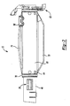
- Figure 1 is a perspective view of a modular non-driving front axle constructed in accordance with the teachings of the present invention
- Figure 2 is a fragmentary front view of the modular non-driving front axle of Figure 1;
- FIG. 3 is a perspective view of a modular driving axle assembly constructed in accordance with the teachings of the present invention.
- Figure 4 is an exploded perspective view of the modular driving front axle shown in Figure 3.
- Non-driving axle 10 constructed in the form of non-driving front axle is depicted.
- Non-driving axle 10 includes a sleeve and tube assembly 12, a pair of knuckle assemblies 14 and a pair of wheel end assemblies 16.
- Non-driving axle 10 functions to support a portion of the vehicle load and provide articulating wheel end assemblies for steering.
- Each wheel end assembly 16 includes a hub 18, a brake rotor 20, a hub extension 22 and an outer shaft 24. Each of these components are free to rotate about the longitudinal axis of outer shaft 24.
- a hub nut 26 couples outer shaft 24 to hub 18.
- Various fasteners and seals that are not specifically identified complete wheel end assembly 16.
- Each knuckle assembly 14 includes a steering knuckle 28 and a brake caliper 30.
- Knuckle assembly 14 is pivotally coupled to sleeve and tube assembly 12 by an upper ball joint 32 and a lower ball joint 34.
- Brake caliper 30 includes a pair of brake pads 36 positioned on each side of brake rotor 20.
- Sleeve and tube assembly 12 includes a first tube assembly 38 and a second tube assembly 40 interconnected by a sleeve 42.
- First tube assembly 38 and second tube assembly 40 may be fixed to sleeve 42 using a number of manufacturing techniques.
- the first and second tube assemblies are press-fit to sleeve 42.
- the first and second tube assemblies may be welded or otherwise mechanically fastened to sleeve 42.
- Specifically contemplated processes include puddle welding, slug welding and riveting.
- a series of radially extending apertures 44 are formed in sleeve 42. Apertures 44 are at least partially filled with a meltable weld material. A current is passed through the tube assembly and the sleeve which causes the weld material to melt. Upon cooling, the weld material adheres to both the tube assembly and the sleeve.
- First tube assembly 38 is substantially similar to second tube assembly 40. Accordingly, only first tube assembly 38 will be described in detail.
- First tube assembly 38 includes a tube 46, a yoke 48, a jounce pad 50 and a number of brackets 52 useful for interconnecting sleeve and tube assembly 12 with a number of vehicle suspension components.
- brackets 52 include a roll stop 54, an upper control arm bracket 56, a lower control arm bracket 58, and a spring seat 60.
- Tube 46 includes a first end 62 and a second end 64. First end 62 is coupled to yoke 48. Second end 64 may be coupled to sleeve 42 as previously described or to a differential axle housing as will be described in greater detail hereinafter.
- brackets 52 and jounce pad 50 are preferably constructed from stamped steel sheets and formed to a desired shape. The formed stampings are then welded to tube 46. Similarly, yoke 48 is preferably welded to tube 46. Alternate processes such as press-fitting, adhesive bonding or installation of mechanical fasteners are also contemplated.
- Sleeve 42 is preferably a cast component requiring little or no machining prior to assembly to the first and second tube assemblies.
- sleeve 42 may be formed from tubing with brackets welded to the tube as required.
- sleeve 42 includes integrally cast features such as a jounce pad 66 to alleviate the need for subsequent bracket welding.
- Sleeve 42 also includes a substantially cylindrical body 68 and a plurality of ribs 70 longitudinally extending along body 68.
- Body 68 includes a first end 72 and a second end 74.
- First end 72 has a collar 76 with an inner cylindrical surface 78 sized to engage an outer surface of tube 46.
- Second end 74 includes a similar collar 82 having an inner surface in engagement with an outer surface of the tube from second tube assembly 40.
- Sleeve 42 has an overall length which is substantially the same as the overall length of the differential housing of the driving axle depicted in Figure 3.
- FIGS 3 and 4 depict a modular axle assembly constructed as a driving axle 100.
- Driving axle 100 includes common knuckle assemblies 14, wheel end assemblies 16, first tube assembly 38 and second tube assembly 40.
- First tube assembly 38 and second tube assembly 40 are joined to a differential housing 102 to form a sleeve and housing assembly 104.
- Differential housing 102 includes a pair of axially aligned apertures 106 for receipt of first tube assembly 38 and second tube assembly 40.
- the first and second tube assemblies are coupled to differential housing 102 using the press-fitting, plug welding and/or mechanical fastening techniques previously described in relation to sleeve 42. It should be appreciated that because of the large number of common components and the common position of the components of the driving and non-driving axles, one set of tooling may likely be used to couple the first and second tube assemblies to the sleeve and/or the differential housing.
- Differential housing 102 also includes an access opening 108 and an input shaft aperture 110.
- a cover 112 encloses access opening 108 after certain driveline components, introduced hereinafter, have been assembled with a cavity 114 defined by differential housing 102.
- Power is transferred to the wheels of driving axle 100 via an input shaft 116, a differential assembly 118 and drive shafts 120.
- Driveshaft 120 is drivingly coupled to outer shaft 24 by a universal joint 122.
- axle assemblies may be constructed using the modular concept described. Utilization of common axle tube assemblies and wheel end assemblies in driving and non-driving axles allows for manufacturing and assembly cost reductions. Furthermore, the costs associated with testing and verification of two entirely different axle assemblies are avoided.
Landscapes
- Engineering & Computer Science (AREA)
- Mechanical Engineering (AREA)
- Chemical & Material Sciences (AREA)
- Combustion & Propulsion (AREA)
- Transportation (AREA)
- General Engineering & Computer Science (AREA)
- Ocean & Marine Engineering (AREA)
- Motor Power Transmission Devices (AREA)
- Shafts, Cranks, Connecting Bars, And Related Bearings (AREA)
- Retarders (AREA)
Applications Claiming Priority (2)
| Application Number | Priority Date | Filing Date | Title |
|---|---|---|---|
| US792661 | 1985-10-29 | ||
| US10/792,661 US7585032B2 (en) | 2003-10-17 | 2004-03-03 | Modular axle assembly |
Publications (3)
| Publication Number | Publication Date |
|---|---|
| EP1571008A2 true EP1571008A2 (de) | 2005-09-07 |
| EP1571008A3 EP1571008A3 (de) | 2008-03-26 |
| EP1571008B1 EP1571008B1 (de) | 2009-09-30 |
Family
ID=34750610
Family Applications (1)
| Application Number | Title | Priority Date | Filing Date |
|---|---|---|---|
| EP04027542A Expired - Lifetime EP1571008B1 (de) | 2004-03-03 | 2004-11-19 | Modulare Achsanordnung |
Country Status (5)
| Country | Link |
|---|---|
| US (2) | US7585032B2 (de) |
| EP (1) | EP1571008B1 (de) |
| KR (1) | KR20050089128A (de) |
| BR (1) | BRPI0405126B1 (de) |
| DE (1) | DE602004023367D1 (de) |
Families Citing this family (26)
| Publication number | Priority date | Publication date | Assignee | Title |
|---|---|---|---|---|
| JP4624814B2 (ja) * | 2005-01-21 | 2011-02-02 | ヤンマー株式会社 | トラクタ |
| US20080143175A1 (en) * | 2006-12-14 | 2008-06-19 | Richard Chambers | Beam axle system |
| US8109000B2 (en) * | 2007-05-31 | 2012-02-07 | American Axle & Manufacturing, Inc. | Salisbury axle assembly |
| CN101808842B (zh) | 2007-09-27 | 2013-10-23 | 美国轮轴制造公司 | 机车轴组件 |
| KR100969383B1 (ko) * | 2008-07-10 | 2010-07-09 | 현대자동차주식회사 | 차량용 스티어링 스톱퍼 유닛 |
| DE102011054580A1 (de) * | 2011-10-18 | 2013-04-18 | Siemens Aktiengesellschaft | Personenkraftwagen sowie Personenkraftwagenmodul |
| WO2013095207A1 (en) * | 2011-12-22 | 2013-06-27 | Volvo Lastavagnar Ab | Vehicle axle housing and a vehicle comprising such an axle housing |
| US9533531B2 (en) | 2012-11-20 | 2017-01-03 | Mitchell Z. Dziekonski | Modular axle shaft assemblies for use with racing vehicles and other vehicles |
| US8460149B1 (en) | 2013-01-25 | 2013-06-11 | American Axle & Manufacturing, Inc. | Differential bearing system for a power transmitting component and method for assembling a power transmitting component |
| US10035394B2 (en) | 2014-04-09 | 2018-07-31 | Cnh Industrial America Llc | Roll angle stop arrangement for a suspension system in an off-road vehicle |
| US9140349B1 (en) | 2014-04-23 | 2015-09-22 | American Axle & Manufacturing, Inc. | Compact axle assembly with locking differential |
| US9919559B2 (en) * | 2014-12-11 | 2018-03-20 | Ford Global Technologies, Llc | Axle carrier housing with a swept support rib |
| CN105584359A (zh) * | 2016-03-28 | 2016-05-18 | 泉州鑫豪工程机械科技有限公司 | 挖掘机转向驱动桥 |
| CN114802439B (zh) * | 2017-06-21 | 2024-11-12 | 亨德里克森美国有限责任公司 | 自转向车桥的转向节 |
| US10791676B2 (en) | 2018-03-28 | 2020-10-06 | Cnh Industrial America Llc | Modular combine traction axle |
| US11772487B2 (en) * | 2018-10-04 | 2023-10-03 | Ronald A. Holland | Vehicle rear drive axle |
| CN109505899B (zh) * | 2019-01-08 | 2023-10-13 | 南京创捷和信汽车零部件有限公司 | 装有常闭式湿式制动器的前轴总成 |
| DE102020200869B4 (de) * | 2020-01-24 | 2024-05-16 | Zf Friedrichshafen Ag | Antriebsachse für ein Kraftfahrzeug |
| IT202000003485A1 (it) | 2020-02-20 | 2021-08-20 | Iveco Spa | Assale di veicolo comprendente un sistema di riduzione integrato migliorato |
| US11535057B2 (en) | 2020-09-09 | 2022-12-27 | Mahindra N.A. Tech Center | Axle assembly with sealed wheel end bearings and sealed pinion input bearings |
| US11225107B1 (en) | 2020-09-09 | 2022-01-18 | Mahindra N.A. Tech Center | Axle carrier housing with reinforcement structure |
| US11648745B2 (en) | 2020-09-09 | 2023-05-16 | Mahindra N.A. Tech Center | Modular tooling for axle housing and manufacturing process |
| US11655891B2 (en) | 2020-09-09 | 2023-05-23 | Mahindra N.A. Tech Center | Method of machining an axle carrier housing |
| US11654769B2 (en) * | 2020-09-30 | 2023-05-23 | Gkn Automotive Limited | Driveline unit housing |
| US12214650B2 (en) * | 2021-03-05 | 2025-02-04 | Dana Heavy Vehicle Systems Group, Llc | Systems for drive axle |
| DE202024102217U1 (de) * | 2024-04-30 | 2025-08-04 | Dana Italia S.R.L. | Anordnung für ein Lenksystem eines Fahrzeugs |
Family Cites Families (21)
| Publication number | Priority date | Publication date | Assignee | Title |
|---|---|---|---|---|
| US1732825A (en) * | 1926-12-27 | 1929-10-22 | Annie Wilson Reboul | Divided axle |
| US2570191A (en) | 1948-07-13 | 1951-10-09 | Koehring Co | Detachable driving axle unit |
| US2911262A (en) | 1955-07-01 | 1959-11-03 | Superior Steel & Malleable Cas | Vehicle axle |
| US3037818A (en) | 1957-02-07 | 1962-06-05 | Rockwell Standard Co | Non-drive axle assembly |
| US4168086A (en) * | 1977-08-01 | 1979-09-18 | Dana Corporation | Radius arm support for a driving axle |
| US4234120A (en) * | 1978-04-06 | 1980-11-18 | United States Steel Corporation | Axle housing assembly |
| US4284158A (en) | 1979-05-07 | 1981-08-18 | Schield Vern L | Detachable differential for vehicle drive train |
| DE3402272C2 (de) * | 1984-01-24 | 1987-01-22 | Daimler-Benz Ag, 7000 Stuttgart | Achsbrücke für Kraftfahrzeuge, insbesondere für antreibbare Achsen von Nutzfahrzeugen |
| US4815338A (en) * | 1984-11-23 | 1989-03-28 | Holan Robert J | Single gear-pair vehicle differential |
| US5105517A (en) | 1989-05-08 | 1992-04-21 | Grant & Miriam Enterprises, Inc. | Method for converting a vehicle to a free towing vehicle |
| US5070745A (en) * | 1990-12-24 | 1991-12-10 | Lindsey Kelly D | Asymmetrical differential drive |
| US5429423A (en) | 1994-01-07 | 1995-07-04 | Dana Corporation | Fabricated front axle I-beam |
| DE19528745A1 (de) * | 1994-08-10 | 1996-02-15 | Dana Corp | Fahrzeug-Antriebsachse |
| US5697677A (en) * | 1995-01-23 | 1997-12-16 | Rockwell Heavy Vehicle Systems, Inc. | Bearing support plate for axle housing |
| US5810377A (en) | 1997-01-21 | 1998-09-22 | The Boler Company | Fabricated steer axle |
| US6024418A (en) | 1997-04-25 | 2000-02-15 | Ebert; James L. | Axle repair method and related assembly |
| DE19920670A1 (de) * | 1999-05-05 | 2000-11-23 | Man Nutzfahrzeuge Ag | Achskörper einer Vorlauf-, Nachlauf- oder Liftachse für Nutzfahrzeuge |
| US6253989B1 (en) * | 2000-01-18 | 2001-07-03 | Meritor Heavy Vehicle Systems, Llc | Press fit joint with puddle weld retention |
| US6398689B1 (en) * | 2000-03-27 | 2002-06-04 | American Axle & Manufacturing, Inc. | One piece differential bearing adjuster lock and fastener |
| US6439672B1 (en) | 2000-09-11 | 2002-08-27 | U.S. Manufacturing Corporation | Vehicle light weight dead axle and method for forming same |
| CN1643273A (zh) * | 2002-03-20 | 2005-07-20 | 丹拿公司 | 汽车用的模件式驱动桥组件 |
-
2004
- 2004-03-03 US US10/792,661 patent/US7585032B2/en active Active
- 2004-11-19 DE DE602004023367T patent/DE602004023367D1/de not_active Expired - Lifetime
- 2004-11-19 EP EP04027542A patent/EP1571008B1/de not_active Expired - Lifetime
- 2004-11-24 BR BRPI0405126-2A patent/BRPI0405126B1/pt active IP Right Grant
- 2004-11-30 KR KR1020040099160A patent/KR20050089128A/ko not_active Withdrawn
-
2007
- 2007-06-13 US US11/818,259 patent/US7559404B2/en not_active Expired - Lifetime
Non-Patent Citations (1)
| Title |
|---|
| None |
Also Published As
| Publication number | Publication date |
|---|---|
| US20070241609A1 (en) | 2007-10-18 |
| BRPI0405126B1 (pt) | 2018-01-23 |
| KR20050089128A (ko) | 2005-09-07 |
| DE602004023367D1 (de) | 2009-11-12 |
| US7559404B2 (en) | 2009-07-14 |
| US20050082780A1 (en) | 2005-04-21 |
| US7585032B2 (en) | 2009-09-08 |
| EP1571008B1 (de) | 2009-09-30 |
| EP1571008A3 (de) | 2008-03-26 |
| BRPI0405126A (pt) | 2005-10-18 |
Similar Documents
| Publication | Publication Date | Title |
|---|---|---|
| US7559404B2 (en) | Modular axle assembly and method | |
| CN111032377B (zh) | 电动车桥传动系组件 | |
| CN102056788B (zh) | 用于全地形车的动力转向装置 | |
| JP2585152B2 (ja) | ステアリングナックルの取付構造 | |
| US20060032895A1 (en) | Method for joining axle components | |
| AU2004224969A1 (en) | Drive axle for motor vehicles and method for assembling the same | |
| US20050277480A1 (en) | Flange assembly for supporting a bearing and an end fitting in a driveshaft assembly | |
| US20080277999A1 (en) | Axle assembly of wheel | |
| JPH10114278A (ja) | 自動車用の一体接合のツーピース形のステアリング・ナックル・アセンブリ及びその製法 | |
| EP1248922B1 (de) | Ausgleichsgetriebe | |
| JP2001080308A (ja) | 車輪軸受装置 | |
| JP2009511839A (ja) | 取付方法における最適比を有する直接トルクフロー連結部 | |
| EP1527934A2 (de) | Anpassbare Flanschvorrichtung für ein Verschlussteil in einer Antriebsachse | |
| JP4090714B2 (ja) | 車輪用軸受装置及びその製造方法 | |
| GB2154186A (en) | An axle casing for motor vehicles | |
| JP3706845B2 (ja) | アクスルハブの支持構造 | |
| JPH0747961A (ja) | 衝撃吸収式ステアリング装置 | |
| KR20200055525A (ko) | 휠옵셋 가변형 휠 조립체 | |
| JP4475849B2 (ja) | 産業車両のドライブアクスル | |
| US20060192423A1 (en) | Axle assembly of driving wheel | |
| US7726000B2 (en) | Method of securing first and second splined members together | |
| JPH1035304A (ja) | プロペラシャフトの衝撃吸収構造 | |
| GB2129884A (en) | A vehicle having a wheel support and a hub bearing unit | |
| JP3872655B2 (ja) | 等速ジョイント用ラビリンスシール構造 | |
| JPH0452082Y2 (de) |
Legal Events
| Date | Code | Title | Description |
|---|---|---|---|
| PUAI | Public reference made under article 153(3) epc to a published international application that has entered the european phase |
Free format text: ORIGINAL CODE: 0009012 |
|
| AK | Designated contracting states |
Kind code of ref document: A2 Designated state(s): AT BE BG CH CY CZ DE DK EE ES FI FR GB GR HU IE IS IT LI LU MC NL PL PT RO SE SI SK TR |
|
| AX | Request for extension of the european patent |
Extension state: AL HR LT LV MK YU |
|
| PUAL | Search report despatched |
Free format text: ORIGINAL CODE: 0009013 |
|
| AK | Designated contracting states |
Kind code of ref document: A3 Designated state(s): AT BE BG CH CY CZ DE DK EE ES FI FR GB GR HU IE IS IT LI LU MC NL PL PT RO SE SI SK TR |
|
| AX | Request for extension of the european patent |
Extension state: AL HR LT LV MK YU |
|
| 17P | Request for examination filed |
Effective date: 20080319 |
|
| AKX | Designation fees paid |
Designated state(s): DE ES FR GB IT |
|
| GRAP | Despatch of communication of intention to grant a patent |
Free format text: ORIGINAL CODE: EPIDOSNIGR1 |
|
| GRAS | Grant fee paid |
Free format text: ORIGINAL CODE: EPIDOSNIGR3 |
|
| GRAA | (expected) grant |
Free format text: ORIGINAL CODE: 0009210 |
|
| AK | Designated contracting states |
Kind code of ref document: B1 Designated state(s): DE ES FR GB IT |
|
| REG | Reference to a national code |
Ref country code: GB Ref legal event code: FG4D |
|
| REF | Corresponds to: |
Ref document number: 602004023367 Country of ref document: DE Date of ref document: 20091112 Kind code of ref document: P |
|
| PG25 | Lapsed in a contracting state [announced via postgrant information from national office to epo] |
Ref country code: ES Free format text: LAPSE BECAUSE OF FAILURE TO SUBMIT A TRANSLATION OF THE DESCRIPTION OR TO PAY THE FEE WITHIN THE PRESCRIBED TIME-LIMIT Effective date: 20100110 |
|
| PLBE | No opposition filed within time limit |
Free format text: ORIGINAL CODE: 0009261 |
|
| STAA | Information on the status of an ep patent application or granted ep patent |
Free format text: STATUS: NO OPPOSITION FILED WITHIN TIME LIMIT |
|
| 26N | No opposition filed |
Effective date: 20100701 |
|
| PG25 | Lapsed in a contracting state [announced via postgrant information from national office to epo] |
Ref country code: IT Free format text: LAPSE BECAUSE OF FAILURE TO SUBMIT A TRANSLATION OF THE DESCRIPTION OR TO PAY THE FEE WITHIN THE PRESCRIBED TIME-LIMIT Effective date: 20090930 |
|
| REG | Reference to a national code |
Ref country code: FR Ref legal event code: PLFP Year of fee payment: 12 |
|
| REG | Reference to a national code |
Ref country code: FR Ref legal event code: PLFP Year of fee payment: 13 |
|
| PGFP | Annual fee paid to national office [announced via postgrant information from national office to epo] |
Ref country code: FR Payment date: 20161014 Year of fee payment: 13 Ref country code: GB Payment date: 20161116 Year of fee payment: 13 |
|
| GBPC | Gb: european patent ceased through non-payment of renewal fee |
Effective date: 20171119 |
|
| REG | Reference to a national code |
Ref country code: FR Ref legal event code: ST Effective date: 20180731 |
|
| PG25 | Lapsed in a contracting state [announced via postgrant information from national office to epo] |
Ref country code: FR Free format text: LAPSE BECAUSE OF NON-PAYMENT OF DUE FEES Effective date: 20171130 |
|
| PG25 | Lapsed in a contracting state [announced via postgrant information from national office to epo] |
Ref country code: GB Free format text: LAPSE BECAUSE OF NON-PAYMENT OF DUE FEES Effective date: 20171119 |
|
| PGFP | Annual fee paid to national office [announced via postgrant information from national office to epo] |
Ref country code: DE Payment date: 20231121 Year of fee payment: 20 |
|
| REG | Reference to a national code |
Ref country code: DE Ref legal event code: R071 Ref document number: 602004023367 Country of ref document: DE |