EP1571071A2 - Automatische Bremsleuchte - Google Patents
Automatische Bremsleuchte Download PDFInfo
- Publication number
- EP1571071A2 EP1571071A2 EP05251274A EP05251274A EP1571071A2 EP 1571071 A2 EP1571071 A2 EP 1571071A2 EP 05251274 A EP05251274 A EP 05251274A EP 05251274 A EP05251274 A EP 05251274A EP 1571071 A2 EP1571071 A2 EP 1571071A2
- Authority
- EP
- European Patent Office
- Prior art keywords
- light
- automatic braking
- holder
- braking light
- resilient spring
- Prior art date
- Legal status (The legal status is an assumption and is not a legal conclusion. Google has not performed a legal analysis and makes no representation as to the accuracy of the status listed.)
- Withdrawn
Links
- 230000001133 acceleration Effects 0.000 description 2
- QSHDDOUJBYECFT-UHFFFAOYSA-N mercury Chemical compound [Hg] QSHDDOUJBYECFT-UHFFFAOYSA-N 0.000 description 2
- 229910052753 mercury Inorganic materials 0.000 description 2
- 229910052751 metal Inorganic materials 0.000 description 2
- 239000002184 metal Substances 0.000 description 2
- 206010039203 Road traffic accident Diseases 0.000 description 1
- 208000027418 Wounds and injury Diseases 0.000 description 1
- 230000003213 activating effect Effects 0.000 description 1
- 239000003990 capacitor Substances 0.000 description 1
- 239000003086 colorant Substances 0.000 description 1
- 230000001351 cycling effect Effects 0.000 description 1
- 230000006378 damage Effects 0.000 description 1
- 238000001514 detection method Methods 0.000 description 1
- 238000010586 diagram Methods 0.000 description 1
- 208000014674 injury Diseases 0.000 description 1
- 230000002035 prolonged effect Effects 0.000 description 1
- 238000005096 rolling process Methods 0.000 description 1
Images


Classifications
-
- B—PERFORMING OPERATIONS; TRANSPORTING
- B60—VEHICLES IN GENERAL
- B60Q—ARRANGEMENT OF SIGNALLING OR LIGHTING DEVICES, THE MOUNTING OR SUPPORTING THEREOF OR CIRCUITS THEREFOR, FOR VEHICLES IN GENERAL
- B60Q1/00—Arrangement of optical signalling or lighting devices, the mounting or supporting thereof or circuits therefor
- B60Q1/26—Arrangement of optical signalling or lighting devices, the mounting or supporting thereof or circuits therefor the devices being primarily intended to indicate the vehicle, or parts thereof, or to give signals, to other traffic
- B60Q1/44—Arrangement of optical signalling or lighting devices, the mounting or supporting thereof or circuits therefor the devices being primarily intended to indicate the vehicle, or parts thereof, or to give signals, to other traffic for indicating braking action or preparation for braking, e.g. by detection of the foot approaching the brake pedal
- B60Q1/445—Arrangement of optical signalling or lighting devices, the mounting or supporting thereof or circuits therefor the devices being primarily intended to indicate the vehicle, or parts thereof, or to give signals, to other traffic for indicating braking action or preparation for braking, e.g. by detection of the foot approaching the brake pedal controlled by inertial devices
-
- B—PERFORMING OPERATIONS; TRANSPORTING
- B62—LAND VEHICLES FOR TRAVELLING OTHERWISE THAN ON RAILS
- B62J—CYCLE SADDLES OR SEATS; AUXILIARY DEVICES OR ACCESSORIES SPECIALLY ADAPTED TO CYCLES AND NOT OTHERWISE PROVIDED FOR, e.g. ARTICLE CARRIERS OR CYCLE PROTECTORS
- B62J6/00—Arrangement of optical signalling or lighting devices on cycles; Mounting or supporting thereof; Circuits therefor
- B62J6/04—Rear lights
- B62J6/045—Rear lights indicating braking
Definitions
- This invention relates to an automatic braking light or stop light for pedal cycles and the like and is particularly applicable for vehicles with no electric system.
- an automatic braking light for a vehicle including an inertia driven switch circuit and a warning light, wherein the inertia driven switch circuit is arranged to connect a power source to the warning light during deceleration of the vehicle and thereby activate the warning light.
- the present invention seeks to provide an automatic braking light that can be fixed to pedal cycles and other vehicles and is inertia-activated on deceleration.
- the braking light includes a case in which a battery in a holder swings overhead a pivot/axle from a stop where it is at rest forward to a resilient spring means which absorbs the deceleration force and simultaneously closes an electric circuit to a display of light emitting diodes to thereby provide a warning to other road users of the deceleration.
- the inertia driven switch circuit preferably includes a holder for the power source arranged to swing overhead a pivot/axle from a stop where it is at rest forward to a resilient spring, the resilient spring being arranged to absorb the deceleration force and simultaneously connect the power source to the warning light.
- the holder is preferably arranged to swing in an arc between predetermined angles of rest and arrest, said angles being maintained by rigid attachment of the unit to the vehicle.
- the resilient spring preferably comprises a leaf spring, the angle and tension of the leaf spring being selected so as to absorb the forward momentum of the holder on deceleration, and to deflect the holder to the rest position upon cessation of decelerating forces.
- the resilient spring is preferably electrically conductive and is connected to the warning light which is in turn connectable to a pole of the power source, the other pole of the power source being connectable to an electrical contact on the exterior of the holder, the electrical contact being positioned to contact the resilient spring during deceleration and thereby close the switch circuit.
- the warning light preferably includes a plurality of light emitting diodes.
- the light emitting diodes may be arranged in a cross shape.
- the braking light may further comprise an override switch, the override switch being arranged to activate at least a number of the light emitting diodes light for continuous operation.
- the braking light may further comprise a further light and a continuous operation switch, the further light being activatable by the continuous operation switch and being independent and visually distinguishable from the warning light.
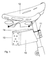
- FIG. 1 shows, in perspective, a braking light according to an embodiment of the present invention fitted to a cycle frame.
- the braking light unit includes a compact case 10 arranged to be secured to the cycle frame 2 under the saddle 12 by a rigid attachment bracket 11 which maintains the angle of operation of the components of the unit Access for battery replacement is via a lid 14 on top of the case 10.
- a nine LED display 15 projects to the rear.
- FIG 2 is a sectional view of the braking light of Figure 1 in an "off” position and Figure 3 is a sectional view of the braking light of Figure 1 in an "on” position.
- the unit 1 includes a battery holder 16 that is arranged to pivot over an offset axle 17. In the "off" position, the battery holder 16 rests on a stop 18 at an angle of approximately 42° above horizontal.
- the nine LED display 15 is mounted on a printed circuit board 20 fitted towards the rear of the case 10, under a translucent cover 21.
- the arc of forward movement of the holder 16 to an "on" position, as shown in Fig 3, is confined to approximately 50°.
- the holder is arrested by an electrically conducting resilient spring 19 (preferably a leaf spring) and a forward stop/front wall of the case which is fixed at an angle of approximately 62° above horizontal.
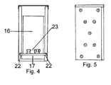
- Figure 4 is a sectional view along the line a-a of Figure 3.
- the battery holder 16 pivots over the axle 17 held in bearings 22 in the side walls of the case.
- the inertia mass is provided by a PP3 9volt battery inserted into positive and negative sockets 23 inside the holder and clipped in place.
- the positive socket is connected to a curved metal shoe 24 on the upper outside of the holder 16, which makes contact with the resilient spring 19 when the holder 16 is thrown forward on deceleration.
- the resilient spring 19 is connected to the positive feed of the LED display 15 via an integral circuit and resistor (not shown).
- a flexible wire 25 connects the negative pole of the battery holder 16 to the negative feed of the LED display 15. Therefore, when the metal shoe 24 of the battery holder 16 contacts with the resilient spring 19, thereby closing the circuit and illuminating the LED display 15.
- this braking light is envisaged to all forms of wheeled conveyances such as tricycles, pedal rickshaws, wheelchairs, powered scooters and railway rolling stock.
- the system can be scaled down or enlarged to suit these situations.
- the nine LED arrangement also lends itself to a triangular configuration, although other numbers, colors or arrangements of LEDs (or other lighting elements) can be envisaged and substituted for those described herein.
- other warning means could be used, such as a horn, a bell, a mechanical indicator or an electronic display.
- the lighting time of the LED can be prolonged by the addition of a capacitor or similar element or circuit.
- the braking light can be modified to incorporate a continuous three-LED display tail light with manual switch for night operation.
- the three-LED display may be of a different pattern and/or color to the warning light and mounted in the same housing. Alternatively, three LEDs could be illuminated with the remainder being activated when the braking circuit is closed.
- inertia change detection systems could be substituted for the battery mounted in a battery holder pivoting over an axle.
- a mercury based switch or the like could be used.
- an incline sensor (again such as a mercury based switch) could be used to avoid the brake light activating when cycling down an incline, over potholes and the like.
- other power sources could be substituted for batteries, for example a rechargeable power source (charged by an external source or by a dynamo attached to the cycle).
- braking light could be attached to the vehicle at other points using an appropriate mount.
Landscapes
- Engineering & Computer Science (AREA)
- Mechanical Engineering (AREA)
- Lighting Device Outwards From Vehicle And Optical Signal (AREA)
Applications Claiming Priority (2)
| Application Number | Priority Date | Filing Date | Title |
|---|---|---|---|
| GB0405079A GB2411714C (en) | 2004-03-06 | 2004-03-06 | A brake warning light |
| GB0405079 | 2004-03-06 |
Publications (2)
| Publication Number | Publication Date |
|---|---|
| EP1571071A2 true EP1571071A2 (de) | 2005-09-07 |
| EP1571071A3 EP1571071A3 (de) | 2006-03-29 |
Family
ID=32088837
Family Applications (1)
| Application Number | Title | Priority Date | Filing Date |
|---|---|---|---|
| EP05251274A Withdrawn EP1571071A3 (de) | 2004-03-06 | 2005-03-03 | Automatische Bremsleuchte |
Country Status (3)
| Country | Link |
|---|---|
| US (1) | US7170402B2 (de) |
| EP (1) | EP1571071A3 (de) |
| GB (1) | GB2411714C (de) |
Cited By (2)
| Publication number | Priority date | Publication date | Assignee | Title |
|---|---|---|---|---|
| EP1862353A1 (de) * | 2006-05-29 | 2007-12-05 | Matthias Ebel | Rückleuchte mit Bremslicht und deren Verfahren |
| DE102011018246A1 (de) * | 2011-04-19 | 2012-10-25 | Dirk Lieske | Mechanische Beschleunigungsanzeige |
Families Citing this family (5)
| Publication number | Priority date | Publication date | Assignee | Title |
|---|---|---|---|---|
| HRP20060171A2 (en) * | 2006-05-10 | 2008-06-30 | Jadreško Atilio | Stop light with inertia switch and position light on the helmet of a motocyclist or a bicyclist |
| TWM359479U (en) * | 2009-03-03 | 2009-06-21 | Acxing Ind Co Ltd | Bicycle display lamp |
| US9340246B2 (en) | 2014-05-01 | 2016-05-17 | John Desmond Woram | Bicycle brake light with graduated deceleration dependent lighting |
| US10696214B2 (en) | 2018-01-10 | 2020-06-30 | Toyota Motor Engineering & Manufacturing North America, Inc. | Automatic brake light activation system |
| DE202018000627U1 (de) * | 2018-02-08 | 2018-02-23 | Michael Huprich | Rollstuhlfußstütze |
Family Cites Families (12)
| Publication number | Priority date | Publication date | Assignee | Title |
|---|---|---|---|---|
| US2547199A (en) * | 1947-12-05 | 1951-04-03 | All American Novelty Company I | Electric signal switch |
| US2982944A (en) * | 1959-04-13 | 1961-05-02 | Robert W Weller | Vehicle signaling device |
| US3601564A (en) * | 1970-01-12 | 1971-08-24 | Lynn E Ellison | Inertia switch for deceleration signaling system |
| US3731022A (en) * | 1971-11-12 | 1973-05-01 | Alcotronics Corp | Inertia type switch with coaxial conductive springs |
| US4176390A (en) * | 1977-02-04 | 1979-11-27 | Galbert-French, Inc. | Light |
| DE3313678A1 (de) * | 1983-04-15 | 1984-10-18 | Licentia Patent-Verwaltungs-Gmbh, 6000 Frankfurt | Brems-warnsystem fuer fahrzeuge |
| DE4431982A1 (de) * | 1993-09-11 | 1995-03-23 | Danny Chiou | Bremsleuchte eines Fahrzeuges, insbesondere Fahrrades |
| DE29600919U1 (de) | 1996-01-19 | 1997-05-15 | Yang, Zih-Ming, Hsin Ying, Tainan | Kraftfahrzeug-Bremslicht-Steuervorrichtung |
| DE29812874U1 (de) | 1998-07-20 | 1998-11-05 | Merlaku, Kastriot, 84347 Pfarrkirchen | Automatisches Bremslichtsystem mit Trägheits-Sensoren für Fahrräder |
| DE29812876U1 (de) * | 1998-07-20 | 1998-11-05 | Merlaku, Kastriot, 84347 Pfarrkirchen | Automatisches Bremslichtsystem mit Trägheits-Sensoren für Fahrzeuge aller Art |
| DE29907485U1 (de) * | 1999-04-29 | 2000-01-20 | Bergerhausen, Karl, Dipl.-Ing (FH), 45772 Marl | Zusatzbremsleuchte für Fahrzeuge aller Art |
| US6527408B1 (en) * | 2000-04-11 | 2003-03-04 | Ronald R. Korenek, Jr. | Motion actuated light device |
-
2004
- 2004-03-06 GB GB0405079A patent/GB2411714C/en not_active Expired - Fee Related
-
2005
- 2005-03-02 US US11/071,595 patent/US7170402B2/en not_active Expired - Fee Related
- 2005-03-03 EP EP05251274A patent/EP1571071A3/de not_active Withdrawn
Non-Patent Citations (1)
| Title |
|---|
| None |
Cited By (3)
| Publication number | Priority date | Publication date | Assignee | Title |
|---|---|---|---|---|
| EP1862353A1 (de) * | 2006-05-29 | 2007-12-05 | Matthias Ebel | Rückleuchte mit Bremslicht und deren Verfahren |
| DE102011018246A1 (de) * | 2011-04-19 | 2012-10-25 | Dirk Lieske | Mechanische Beschleunigungsanzeige |
| DE102011018246B4 (de) * | 2011-04-19 | 2013-07-18 | Dirk Lieske | Mechanische Beschleunigungsanzeige |
Also Published As
| Publication number | Publication date |
|---|---|
| GB2411714B (en) | 2006-03-15 |
| GB0405079D0 (en) | 2004-04-07 |
| US20050200470A1 (en) | 2005-09-15 |
| EP1571071A3 (de) | 2006-03-29 |
| GB2411714A (en) | 2005-09-07 |
| GB2411714C (en) | 2006-08-08 |
| US7170402B2 (en) | 2007-01-30 |
Similar Documents
| Publication | Publication Date | Title |
|---|---|---|
| US7490965B2 (en) | Bicycle lighting apparatus with mountable display | |
| US5008782A (en) | Lighted handlebar for bicycles | |
| US5663707A (en) | Signalling light visible through a rear view window of a vehicle | |
| US5702172A (en) | Light emitting bicycle pedal | |
| US20180201181A1 (en) | Helmet lighting system | |
| US7806070B2 (en) | Method and apparatus for a vehicle forward direction signal | |
| GB2292450A (en) | Safety device for a vehicle | |
| US7170402B2 (en) | Automatic braking light | |
| US12128980B2 (en) | Apparatuses and methods for crank-based lighting | |
| JP2018020751A (ja) | 方向指示灯・ブレーキ灯付き自転車用照明装置。 | |
| CA2811721A1 (en) | Bicycle lighting apparatus and method of use | |
| CN101611934A (zh) | 可发出行车警示信号的衣物 | |
| EP1394029A2 (de) | Fahrradbeleuchtung | |
| GB2122786A (en) | Gravity activated signalling devices | |
| CN201132501Y (zh) | 行车警示装置 | |
| GB2243207A (en) | Direction indicator apparatus | |
| US20040065249A1 (en) | Vehicle direction signal device | |
| US20200309338A1 (en) | Motorcycle visibility led light system | |
| KR101009948B1 (ko) | 자전거용 신호 및 안전 표시등 | |
| KR200212476Y1 (ko) | 자전거 안전 주행장치 | |
| US20120081887A1 (en) | Self-Contained, Portable Headlamp, Automatic Brake-light, And Articulable Battery System | |
| JP3130051U (ja) | 点灯表示装置 | |
| CN102009726A (zh) | 自行车用握套结构 | |
| JP3215627U (ja) | 車幅灯を備えた方向指示器 | |
| JP3073222U (ja) | 警告灯 |
Legal Events
| Date | Code | Title | Description |
|---|---|---|---|
| PUAI | Public reference made under article 153(3) epc to a published international application that has entered the european phase |
Free format text: ORIGINAL CODE: 0009012 |
|
| AK | Designated contracting states |
Kind code of ref document: A2 Designated state(s): AT BE BG CH CY CZ DE DK EE ES FI FR GB GR HU IE IS IT LI LT LU MC NL PL PT RO SE SI SK TR |
|
| AX | Request for extension of the european patent |
Extension state: AL BA HR LV MK YU |
|
| PUAL | Search report despatched |
Free format text: ORIGINAL CODE: 0009013 |
|
| AK | Designated contracting states |
Kind code of ref document: A3 Designated state(s): AT BE BG CH CY CZ DE DK EE ES FI FR GB GR HU IE IS IT LI LT LU MC NL PL PT RO SE SI SK TR |
|
| AX | Request for extension of the european patent |
Extension state: AL BA HR LV MK YU |
|
| 17P | Request for examination filed |
Effective date: 20060918 |
|
| AKX | Designation fees paid |
Designated state(s): AT BE BG CH CY CZ DE DK EE ES FI FR GB GR HU IE IS IT LI LT LU MC NL PL PT RO SE SI SK TR |
|
| STAA | Information on the status of an ep patent application or granted ep patent |
Free format text: STATUS: THE APPLICATION IS DEEMED TO BE WITHDRAWN |
|
| 18D | Application deemed to be withdrawn |
Effective date: 20081001 |