EP1571106A2 - Transporteur à vis pour des cintres à vêtements - Google Patents
Transporteur à vis pour des cintres à vêtements Download PDFInfo
- Publication number
- EP1571106A2 EP1571106A2 EP05008772A EP05008772A EP1571106A2 EP 1571106 A2 EP1571106 A2 EP 1571106A2 EP 05008772 A EP05008772 A EP 05008772A EP 05008772 A EP05008772 A EP 05008772A EP 1571106 A2 EP1571106 A2 EP 1571106A2
- Authority
- EP
- European Patent Office
- Prior art keywords
- screw conveyor
- conveying
- worm shaft
- hangers
- groove
- Prior art date
- Legal status (The legal status is an assumption and is not a legal conclusion. Google has not performed a legal analysis and makes no representation as to the accuracy of the status listed.)
- Granted
Links
Images


Classifications
-
- B—PERFORMING OPERATIONS; TRANSPORTING
- B65—CONVEYING; PACKING; STORING; HANDLING THIN OR FILAMENTARY MATERIAL
- B65G—TRANSPORT OR STORAGE DEVICES, e.g. CONVEYORS FOR LOADING OR TIPPING, SHOP CONVEYOR SYSTEMS OR PNEUMATIC TUBE CONVEYORS
- B65G47/00—Article or material-handling devices associated with conveyors; Methods employing such devices
- B65G47/52—Devices for transferring articles or materials between conveyors i.e. discharging or feeding devices
- B65G47/60—Devices for transferring articles or materials between conveyors i.e. discharging or feeding devices to or from conveyors of the suspended, e.g. trolley, type
- B65G47/61—Devices for transferring articles or materials between conveyors i.e. discharging or feeding devices to or from conveyors of the suspended, e.g. trolley, type for articles
-
- B—PERFORMING OPERATIONS; TRANSPORTING
- B65—CONVEYING; PACKING; STORING; HANDLING THIN OR FILAMENTARY MATERIAL
- B65G—TRANSPORT OR STORAGE DEVICES, e.g. CONVEYORS FOR LOADING OR TIPPING, SHOP CONVEYOR SYSTEMS OR PNEUMATIC TUBE CONVEYORS
- B65G33/00—Screw or rotary spiral conveyors
- B65G33/02—Screw or rotary spiral conveyors for articles
-
- B—PERFORMING OPERATIONS; TRANSPORTING
- B65—CONVEYING; PACKING; STORING; HANDLING THIN OR FILAMENTARY MATERIAL
- B65G—TRANSPORT OR STORAGE DEVICES, e.g. CONVEYORS FOR LOADING OR TIPPING, SHOP CONVEYOR SYSTEMS OR PNEUMATIC TUBE CONVEYORS
- B65G2201/00—Indexing codes relating to handling devices, e.g. conveyors, characterised by the type of product or load being conveyed or handled
- B65G2201/02—Articles
- B65G2201/0229—Clothes, clothes hangers
Definitions
- the invention relates to a screw conveyor according to the preamble of the claim 1.
- screw conveyors are used to transport hangers hanging garments used, such as in the context of a suspension conveyor for the sorting and picking of garments.
- the hangers are doing with their upper hanger hook into a flight hooked, which formed on the outer surface of a worm shaft is. If the worm shaft is driven in rotation about its shaft axis, then the hangers taken up in the helix are moved in the direction of the Wave axis moved.
- the Branching worm course along the worm shaft he can deal with one unite other helix, it may create new helical flights and the like, therefore here generally of one on the outer surface of the Worm shaft formed screw or conveyor system is mentioned.
- the object of the invention is therefore to provide a screw conveyor of the generic type Specify type, the reliable operation even with large production capacity guaranteed.
- the invention is based on a screw conveyor for the transport of suspended on hangers conveyed, in particular Hangers hanging garments comprising one around its shaft axis rotatably mounted worm shaft with one on the outer surface formed of the screw shaft, snail-like around the shaft axis spiraling conveyor system into which the suspension beams with upper carrier hook suspendable and therein by turning the worm shaft strand in one Conveying direction are axially conveyed, wherein along the worm shaft at least one of the separation of the suspension carrier serving singler with a single conveying groove designed for the individual lifting of the hanging carrier is formed.
- the single conveying groove in the separating region having successive Nutwindungen whose slope approximately equal to or slightly smaller than the material thickness of the suspension hooks in the area their intervention in the individual benefit groove is.
- the conveyor system for training the hanging carrier in the Einzel complicatednut one along the winding direction of the conveyor gear system funnel-like tapered Einweise themegang for the suspension carrier, which at least on a part of its winding direction at its length relative to the conveying direction front edge substantially free of ribs on the Einzel themenut adjacent, such that of several in the Einweise themegang run in suspension supports upon rotation of the worm shaft strand in the conveying direction preceded by this suspension carrier enters the Einzel complexitynut.
- the one-piece made of several separate, but non-rotatably connected Wellen Kunststoffe can be constructed, as well as a segmented shaft train with several coaxially arranged one behind the other, rotatable relative to each other Understood wave segments.
- Such relatively rotatable shaft segments allow, if necessary, different sections of the worm shaft train to drive at different speeds.
- the worm shaft strand at least on a part of the length the Einweise complexitygangs a from the front edge of the Einweise complexitygangs in Direction to the rear edge to have increasing wave radius, so that the suspension beams in the Einweise occasiongang so to speak on a sloping Track can slide down to the front edge of Einweise mechanicgangs.
- the Einweise themegang extends between two adjacent Nutwindened the Einzel basicnut into, such that of several run into the Einweise themegang hangers upon rotation of the Worm shaft of the leading in the conveying direction of this suspension carrier enters the front Nutwindung the Einzel fundamentalnut and the immediately following Hanging support enters the rear groove winding of the single conveying groove.
- the one-way conveyor be such is designed that, in the case of the entry of three or more hangers in the Einweise themegang upon rotation of the worm shaft strand in the conveying direction third consecutive and, if appropriate, each succeeding suspension carrier from a front gangway the Einweise complexitygangs in an immediately subsequent Gangwindung the Einweise themegangs be thrown back.
- the accumulation conveying area can be a secondary accumulation conveying area be, via an intermediate conveyor line from an upstream Primary accumulation conveying area of the screw conveyor can be loaded with suspended supports is, wherein the primary accumulation area assigned a switchable stop stop is, by means of which the suspension beams in the primary accumulation conveying area can be stowed are.
- the secondary accumulation conveyor area can be assigned to a traffic jam detector, which upon reaching a predetermined stowage length in the secondary accumulation conveying area provides a message signal.
- One connected to the traffic jam electronic control unit of the screw conveyor can then the switching state the stop stop depending on the message signal control, so that always one certain amount of hanging support under low dynamic pressure at the separation area can wait. It has been shown that it allows such training along the worm shaft with a single stop stop get along.
- a separation area can also be in the conveying direction to a Entfädelungs Symposium follow the screw conveyor, in which the conveyor system is designed for Entfädelung crossed HCodeeieri.
- the conveyor system is designed for Entfädelung crossed HCodee.
- the mechanical Entfädelung crossed HCodee can namely happen that two or more hangers in a common Gangwindung the conveyor system the Entfädelungs Scheme leave and therefore there is a separation requirement.
- a cross-over detection area follow the screw conveyor, which for sensory detection Crossed hanging support is formed.
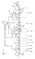
- the screw conveyor shown in Fig. 1 is used for transporting hangers 10, which from an upstream transport system 12 and delivered to the Be conveyed screw conveyor. After she along the screw conveyor Having passed through a conveying direction 14, the hanging support 10 to a Downstream transport system 16 issued that the hanging support 10 to her transported away further use.
- the hangers 10 are in the present example case to hangers, each having an upper hanger hook 18th have and are hung with garments not shown. It It is understood that the screw conveyor in principle also for transport any other hangers may serve instead of such hangers. That the Hanger 10 delivering transport system 12 may, for example, a latch conveyor be while the hanger 10 wegtransportierende transport system 16, for example, a suspension conveyor with movable on rollers Can be single strap carriers.
- hanger 10 For arrival and removal of the hanger 10 can of course, other transport systems than the aforementioned used be, for example, a suspension conveyor with movable on rollers Multi-bar carriers, often referred to as trolleys, and a support bar have, on the several hangers 10 can be hung.
- a suspension conveyor with movable on rollers Multi-bar carriers often referred to as trolleys
- a support bar have, on the several hangers 10 can be hung.
- the screw conveyor has a worm shaft 20, which with his Shaft axis 22 is arranged parallel to the conveying direction 14 and about this axis 22 is rotatably mounted on a support structure, not shown.
- a support structure not shown.
- At the Outer surface of the worm shaft 20 is a along the shaft axis 22 helically trained around this spiraling conveyor system 24, in which the hangers 10 with their hanger hooks 18 are suspended. Will the Worm shaft 20 is set in rotation about its shaft axis 22, so the hanging hangers 10 are moved in the axial direction.
- the conveyor system 24 is shown as a schematic drawing of FIG. as if it had only a single conveyor or flight, with a constant pitch over the entire length of the worm shaft 20 extends.
- the conveyor system 24 at least partially can have a plurality of side-by-side worm threads and that the pitch of each flight along the shaft axis 22 is variable can be.
- the pitch of each flight along the shaft axis 22 is variable can be.
- branching or joining points are present, in which a helix branched or two flights converge.
- the Gang pitch or / and the number of flights can be different Tasks are performed, which are made on the hangers 10 as they go through the screw conveyor.
- a generally 26th designated rotary drive device For the rotary drive of the worm shaft 20 is a generally 26th designated rotary drive device.
- This rotary drive device 26 has at least one preferably at an axial distance from the longitudinal ends of Worm shaft 20 arranged on flexible drive belt 28, which the worm shaft 20 on a partial circumference of the outer surface driving force transmitting, for example by means of interlocking Veryakept, wraps around and by means of an electric motor drive 30 to circulation is drivable in an endless loop.
- Fig. 1 are two such drive belt 28 shown.
- the two drive belts are in axial Spaced apart from each other and each drive one of each independently two mutually coaxial strand segments 32, 34 of the worm shaft 20, which are separated from each other at a separation point 36 and independently from each other about the shaft axis 22 are rotatable.
- a the operation of the screw conveyor Controlling electronic control unit 38 allows one another independent, in particular variable-speed, control of the drives 30.
- FIG. 1 Two such conveying grooves are shown in FIG. 1 dashed lines at the right drive belt 28 and there with 40th designated.
- the conveyor grooves are designed and so to the conveyor system 24 of the worm shaft 20 aligned that hanger 10, which is one of the drive belt 28 approach, from the conveyor system 24 directly in one of the conveyor grooves can run in and after crossing the concerned Drive belt 28 trouble-free back into the feed system 24 of the worm shaft 20 thread.
- a Adjusting ring 42 may be arranged.
- the screw conveyor hanger 10 may be abandoned in disorderly heaps on the screw conveyor, wherein the screw conveyor has the task to promote the hangers 10, to to separate, to disentangle, to clock and to count, so that they one by one leave the screw conveyor.
- the Worm shaft 20 functionally divided into different areas. From the right in Fig. 1 longitudinal end of the worm shaft 20 ago are this successively: a takeover area 44, a large storage area 46, a conveyor area 48, a small storage area 50, a first separation area 52, a de-filing area 54, a second dicing area 56, a crossover detection area 58 and a transfer area 60.
- a takeover area 44 From the right in Fig. 1 longitudinal end of the worm shaft 20 ago are this successively: a takeover area 44, a large storage area 46, a conveyor area 48, a small storage area 50, a first separation area 52, a de-filing area 54, a second dicing area 56, a crossover detection area 58 and a transfer
- the hangers 10 of the transport system 12 taken and transported in the conveying direction 14 to the storage area 46.
- the front end of the jam area 46 is defined by a stop stop 62, by means of an actuator 64, for example a solenoid actuator, between a stop position in which he docks the incoming hangers 10, and a release position is switchable, in which the hangers 10 to him can pass.
- the worm shaft 20 is as so-called accumulation conveyor formed, i. the hangers 10 are in the conveying direction 14 as long as they encounter no resistance. However, meet her stay on the stop stop 62 or a hanger piled up in front of them They stand.
- the hangers 10 then enter the storage area 50, in which the worm shaft 20 is in turn made stowable.
- the Damping in the storage area 50 is not effected by a switchable stop stop, but is effected by the separation area 52, in front of which back hang the hangers 10, if they in a fürschleuskapaztician the Separation range 52 are exceeded.
- the transfer area 60 are the hangers 10 finally on the transport system 16th to hand over.
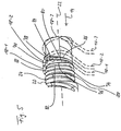
- the separation areas 52, 56 are in Essentially identically constructed, so that it is sufficient, one of the separation areas 52, 56 to explain. In FIGS. 2-6, this is the singulation area 52.
- the conveyor system 24 has a following as Einzzungsungsnut designated single conveying groove 68, whose approximately V-shaped Cross section is dimensioned so that per turn only one hanger hook 18 in the separating groove 68 can be received.
- the turns of the singulation groove 68 are narrow adjacent; the groove pitch corresponds approximately to the material thickness of the hanger hook 18th or is even smaller.
- the pitch of the singling groove 68 is greater than in the central part and gradually increases in the winding direction to the value in the central part from.
- the slope decreases the singling groove 68 closed again; the turns of the singling groove 68 accordingly, they move away from each other again.
- the conveyor system 24 forms a from the previous functional area of the screw conveyor, here the Storage area 50, clothes hangers 10 fed Einweise themegang 70, the hereinafter referred to as gap closure.
- the gap closing 70 winds around the axis 22, preferably by more than one turn, and tapers in the winding direction in the manner of a funnel, until finally in a pointed tapered taper end 72 ends. He forms a flat in the conveying direction 14 Conveyor for the hanger 10, the radial level above the bottom of the groove Singling groove 68 is located.
- a barrier rib 74 which extends over the radial Level of the conveying path of the gap closing 70 raises and the separation groove 68 separates from the gap closing 70.
- This barrier rib 74 causes Clothes hanger 10 as soon as it passes over the front edge of the gap closing 70 in the singling groove 68 have run in, held in the separating groove 68 and be transported in it.
- the approximate place of springing of the barrier rib 74 is clearly visible in FIG. 5 at 76.
- the barrier rib 74 In the winding direction after the end of the rejuvenation 72 of the gap closing passage 70 forms the barrier rib 74 in the central part of the separation region 52 an immediate separation between the successive Turns of the singling groove 68.
- the propulsion and compression rib 78 causes at Rotation of the worm shaft 20 an axial propulsion in the gap closing passage 70 run in hangers 10 toward the front edge of the gap closing passage 70. Since with increasing angle of rotation of the worm shaft strand 20, the axial width of the gap closing passage 70 is smaller takes place at the same time a compression of the hanger hooks 18 of these hanger 10.
- the propulsion and compression rib 78 is configured such that initially, when the axial width the gap closing 70 is still relatively large and the compression pressure is correspondingly low, the propulsion and compression rib 78, the hangers 10 in the gap closing passage 70 can hold. From a certain narrowing of the gap closing passage 70, however, the compression pressure becomes so strong that a rear part of the group of the pasted in the gap closing 70 Clothes hanger 10 over the propulsion and compression rib 78 away to the rear is thrown back in a previous turn of the gap closing passage 70.
- FIGS Separation area 52 are explained for an example case in which enter three hangers 10 at the same time in the gap closing passage 70.
- the worm shaft 20 is thereby further rotated by 90 °, so FIG. 6 shows the same rotational position of the worm shaft strand 20 as FIG. 2 shows, however, after a further rotation by 360 °.
- the three hangers are indicated in Figs. 2-6 with 10-1, 10-2 and 10-3; Accordingly, her hanger hooks with 18-1, 18-2 and 18-3 are designated.
- Fig. 2 are the hangers 10-1, 10-2, 10-3 in an initial section the gap closing passage 70 in which the axial width of the gap closing passage 70 is still so great that no compression effect on the hanger hooks 18-1, 18-2, 18-3 this hanger is exercised.
- the gap closing passage narrows 70 more.
- the two remaining in the gap 70 closing Hanger hooks 18-2 and 18-3 thus experience an increasing compression pressure, the from a certain strength causes the rear hanger hook 18-3 the Propulsion and compression rib 78 overcomes and in the previous turn of the Gap closure 70 is thrown back.
- the so hacked hanger 10-3 then at the top in front of any further hangers coming from the storage area 50 in the gap closing 70 are fed.
- Fig. 4 is the reflected back Hangers 10-3 are clearly visible.
- Fig. 6 shows the state after a full revolution of the worm shaft 22.
- the front hanger 10-1 and the middle hanger 10-2 are both in the singling groove 68 trained and go through this gapless, i. in successive turns.
- the rear hanger 10-3 is used during the next turn of the worm shaft 20 in the winding 82 of the Einzungsungsnut 68 instructed, so that even between the middle hanger 10-2 and the rear hanger 10-3 no gap arises.
- the following Functional areas of the worm shaft 20 can thus be continuous Clock with a few hangers 10 are fed.
- the worm shaft 20 is on a part the length of the gap closing passage 70 with an axial to the front edge of the Gap closing 70 executed towards slightly decreasing shaft radius.
- the gap closing gear 70 a results in the gap closing gear 70 a from the rear edge to the front edge of something downhill conveyor track, which makes it easier to front hanger 10-1 to the front edge of the gap closing passage 70 to push.
- Fig. 1 There is one at 92 with the control unit 38 connected congestion indicator indicated that a message to the control unit 38 sends when the hangers 10 in the storage area 50 to a Backlog the predetermined place.
- the control unit 38 controls the switching state of the stop stop 62. This Control is done in such a way that there is always a certain amount of backwater the separation area 52 is maintained. If the jam length is shorter, causes the control unit 38 a temporary opening of the stop stop 62, so that hangers 10 from the large storage area 46 in the small storage area Can run after 50. Then reaches the queue length again a predetermined Length, the control unit 38 causes the closure of the stop stop 62.
- Auf This way it is achieved that before the separating region 52 always a certain Quantity hanger 10 pending under relatively low dynamic pressure.
- Another jam detector 94 serves to detect the jam length in the large storage area 46. Depending on its alarm signal, the control unit 38 controls the charge of the screw conveyor with hangers 10. For operation of the screw conveyor All in all a stop stop and a traffic jam are enough.
Landscapes
- Engineering & Computer Science (AREA)
- Mechanical Engineering (AREA)
- Chain Conveyers (AREA)
- Intermediate Stations On Conveyors (AREA)
Applications Claiming Priority (3)
| Application Number | Priority Date | Filing Date | Title |
|---|---|---|---|
| DE10163427A DE10163427A1 (de) | 2001-12-21 | 2001-12-21 | Schneckenförderer zum Transport von an Hängeträgern hängendem Fördergut |
| DE10163427 | 2001-12-21 | ||
| EP02805342A EP1456102B1 (fr) | 2001-12-21 | 2002-12-19 | Transporteur a vis con u pour transporter des matieres a transporter suspendues a des supports de suspension |
Related Parent Applications (2)
| Application Number | Title | Priority Date | Filing Date |
|---|---|---|---|
| EP02805342A Division EP1456102B1 (fr) | 2001-12-21 | 2002-12-19 | Transporteur a vis con u pour transporter des matieres a transporter suspendues a des supports de suspension |
| EP02805342.9 Division | 2002-12-19 |
Publications (3)
| Publication Number | Publication Date |
|---|---|
| EP1571106A2 true EP1571106A2 (fr) | 2005-09-07 |
| EP1571106A3 EP1571106A3 (fr) | 2005-12-14 |
| EP1571106B1 EP1571106B1 (fr) | 2006-10-25 |
Family
ID=7710477
Family Applications (2)
| Application Number | Title | Priority Date | Filing Date |
|---|---|---|---|
| EP02805342A Expired - Lifetime EP1456102B1 (fr) | 2001-12-21 | 2002-12-19 | Transporteur a vis con u pour transporter des matieres a transporter suspendues a des supports de suspension |
| EP05008772A Expired - Lifetime EP1571106B1 (fr) | 2001-12-21 | 2002-12-19 | Transporteur à vis pour des cintres à vêtements |
Family Applications Before (1)
| Application Number | Title | Priority Date | Filing Date |
|---|---|---|---|
| EP02805342A Expired - Lifetime EP1456102B1 (fr) | 2001-12-21 | 2002-12-19 | Transporteur a vis con u pour transporter des matieres a transporter suspendues a des supports de suspension |
Country Status (6)
| Country | Link |
|---|---|
| US (1) | US20050016820A1 (fr) |
| EP (2) | EP1456102B1 (fr) |
| AU (1) | AU2002366744A1 (fr) |
| DE (3) | DE10163427A1 (fr) |
| ES (1) | ES2244837T3 (fr) |
| WO (1) | WO2003053825A1 (fr) |
Families Citing this family (6)
| Publication number | Priority date | Publication date | Assignee | Title |
|---|---|---|---|---|
| US20060254722A1 (en) * | 2002-01-15 | 2006-11-16 | Mario Mainetti | Apparatus and method for removing adhesive labels from garment hangers |
| CN103161056A (zh) * | 2011-12-16 | 2013-06-19 | 鸿富锦精密工业(深圳)有限公司 | 可旋转式晾衣架 |
| CN103587905B (zh) * | 2013-10-28 | 2016-07-20 | 中山市雅家乐衣架有限公司 | 一种螺杆式衣架输送设备 |
| TWI563947B (zh) * | 2015-09-18 | 2017-01-01 | Drying device | |
| AT518878B1 (de) * | 2016-09-09 | 2018-02-15 | Knapp Ag | Automatisiertes Lagersystem zum Transport von in Fahrtrichtung gedrehten Ladungsträgern |
| CN107374482A (zh) * | 2017-08-10 | 2017-11-24 | 温州市迪登洁具有限公司 | 一种可精准复位的马桶刷 |
Family Cites Families (14)
| Publication number | Priority date | Publication date | Assignee | Title |
|---|---|---|---|---|
| US3642111A (en) * | 1970-03-18 | 1972-02-15 | Fmc Corp | Full row container feed system |
| DE3132048C2 (de) * | 1981-08-13 | 1983-10-27 | Krones Ag Hermann Kronseder Maschinenfabrik, 8402 Neutraubling | Vorrichtung zum Vereinzeln von Gefäßen, insbesondere in Gefäßbehandlungsmaschinen |
| DE8228473U1 (de) * | 1982-10-09 | 1983-06-23 | Herbert Kannegiesser Gmbh + Co, 4973 Vlotho | Foerdervorrichtung fuer be- und nicht beladene kleiderbuegel |
| DE8802172U1 (de) * | 1988-02-19 | 1988-05-05 | Wilfried Pavel Maschinenbau, 4802 Halle | Förderschnecke für auf Kleiderbügel hängende Bekleidungsstücke |
| NL8801552A (nl) * | 1988-06-17 | 1990-01-16 | Johannes Gerhardus Christianus | Inrichting voor het van elkaar scheiden en stuksgewijs doorvoeren van op een stang aangevoerde platte voorwerpen. |
| US4995531A (en) * | 1989-06-14 | 1991-02-26 | Bridgestone/Firestone, Inc. | Ring dispenser |
| DE4326024C1 (de) * | 1993-08-03 | 1994-10-06 | Pavel Wilfried Maschinen | Transportanlage für auf Kleiderbügel hängende Bekleidungsstücke |
| DE4427027C2 (de) * | 1994-07-29 | 1997-02-06 | Franz Gaertner | Übernahmevorrichtung |
| DE4431581A1 (de) * | 1994-09-05 | 1996-03-07 | Franz Gaertner | Stauordnende Transportvorrichtung |
| DE29505986U1 (de) * | 1995-04-06 | 1995-06-01 | RSL Logistik GmbH & Co., 86899 Landsberg | Vorrichtung zum Lösen verhedderter Haken |
| DE19514604C2 (de) * | 1995-04-20 | 1997-09-04 | Duerkopp Adler Ag | Vorrichtung zum Vereinzeln von übereinander verkreuzten Bügelhaken |
| DE19615773C2 (de) * | 1996-04-20 | 1998-06-04 | Duerkopp Adler Ag | Verfahren zum Vereinzeln von Förderträgern |
| US5864937A (en) * | 1996-12-20 | 1999-02-02 | Direct Tool, Inc. | Bolt and washer assembly machine and method of assembly |
| US6662979B2 (en) * | 2000-06-21 | 2003-12-16 | John Hutterly | Laundry apparatus |
-
2001
- 2001-12-21 DE DE10163427A patent/DE10163427A1/de not_active Withdrawn
-
2002
- 2002-12-19 WO PCT/EP2002/014601 patent/WO2003053825A1/fr not_active Ceased
- 2002-12-19 EP EP02805342A patent/EP1456102B1/fr not_active Expired - Lifetime
- 2002-12-19 EP EP05008772A patent/EP1571106B1/fr not_active Expired - Lifetime
- 2002-12-19 AU AU2002366744A patent/AU2002366744A1/en not_active Abandoned
- 2002-12-19 ES ES02805342T patent/ES2244837T3/es not_active Expired - Lifetime
- 2002-12-19 DE DE50204205T patent/DE50204205D1/de not_active Expired - Fee Related
- 2002-12-19 DE DE50208564T patent/DE50208564D1/de not_active Expired - Fee Related
- 2002-12-19 US US10/499,193 patent/US20050016820A1/en not_active Abandoned
Also Published As
| Publication number | Publication date |
|---|---|
| EP1456102B1 (fr) | 2005-09-07 |
| EP1571106B1 (fr) | 2006-10-25 |
| DE50208564D1 (de) | 2006-12-07 |
| EP1571106A3 (fr) | 2005-12-14 |
| ES2244837T3 (es) | 2005-12-16 |
| EP1456102A1 (fr) | 2004-09-15 |
| DE50204205D1 (de) | 2005-10-13 |
| WO2003053825A1 (fr) | 2003-07-03 |
| US20050016820A1 (en) | 2005-01-27 |
| DE10163427A1 (de) | 2003-07-03 |
| AU2002366744A1 (en) | 2003-07-09 |
Similar Documents
| Publication | Publication Date | Title |
|---|---|---|
| EP3315433B1 (fr) | Dispositif de transmission pour support de produits doté des moyens de retenue | |
| EP2923974B1 (fr) | Dispositif et procédé d'agencement peu encombrant de marchandises suspendues | |
| DE202016009214U1 (de) | Vorrichtung zur Versorgung eines Zwischenförderers | |
| EP3281891A1 (fr) | Système de transfert comprenant un dispositif de poussée pour marchandises au détail | |
| WO2006108486A1 (fr) | Dispositif de transport comprenant au moins une glissiere pour des articles de detail et procede pour empiler des articles de detail dans un conteneur | |
| EP1073601A1 (fr) | Systeme de traitement pour traiter des colis | |
| EP1438244B1 (fr) | Transporteur helicoidal pour acheminer des articles suspendus a des supports de suspension | |
| EP1456102B1 (fr) | Transporteur a vis con u pour transporter des matieres a transporter suspendues a des supports de suspension | |
| DE2015512A1 (de) | Umsetzvorrichtung für Behälter zwischen einem ersten und einem zweiten Förderer | |
| DE19856649C2 (de) | Verfahren und Einrichtung zum Speichern von Fördergut | |
| DE3590101C2 (de) | Vorrichtung zum st}ckweisen Erfassen und Welterf¦rdern von St}ckg}tern | |
| DE2504264C2 (de) | Fördervorrichtung mit Zwischenspeicher | |
| DE2446707C3 (de) | Förderer, insbesondere für Hopfenpflückmaschinen | |
| CH692453A5 (de) | Kettenspeicher sowie Verfahren zu dessen Beladung. | |
| DE3131135C1 (de) | Durchlaufsperre fuer Gegenstaende einer Behandlungsmaschine | |
| EP4326523B1 (fr) | Dispositif d'alimentation | |
| EP3325384A1 (fr) | Dispositif de séparation de marchandises en vrac | |
| DE3207460C2 (de) | Fördervorrichtung für einer Behandlungsmaschine, insbesondere einer Etikettiermaschine, zuzuführende Gegenstände | |
| WO2005105471A1 (fr) | Dispositif d'acheminement et dispositif de liaison | |
| EP0552752A1 (fr) | Gaine tampon à aimant écarteur | |
| CH713126A2 (de) | Übergabevorrichtung zur vereinzelten Übergabe von Produkteträgern mit Haltemitteln an eine Hängefördervorrichtung. | |
| DE102009003818A1 (de) | Transportvorrichtung und Verfahren zum Zuführen von Flüssigkeitsbehältern zu einer Verpackungsmaschine | |
| EP1681249A1 (fr) | Trajet de transport pour bouteilles ou conteneurs similaires | |
| DE1611712A1 (de) | Speichereinrichtung und Pressstrecke fuer Anlagen zum Herstellen von Saecken aus Papier,Kunststoffolien u.dgl. | |
| CH671003A5 (fr) |
Legal Events
| Date | Code | Title | Description |
|---|---|---|---|
| PUAI | Public reference made under article 153(3) epc to a published international application that has entered the european phase |
Free format text: ORIGINAL CODE: 0009012 |
|
| 17P | Request for examination filed |
Effective date: 20050421 |
|
| AC | Divisional application: reference to earlier application |
Ref document number: 1456102 Country of ref document: EP Kind code of ref document: P |
|
| AK | Designated contracting states |
Kind code of ref document: A2 Designated state(s): CH DE ES FR GB IT LI |
|
| PUAL | Search report despatched |
Free format text: ORIGINAL CODE: 0009013 |
|
| AK | Designated contracting states |
Kind code of ref document: A3 Designated state(s): CH DE ES FR GB IT LI |
|
| RIC1 | Information provided on ipc code assigned before grant |
Ipc: 7B 65G 47/28 B Ipc: 7B 65G 47/26 B Ipc: 7B 65G 47/61 A Ipc: 7B 65G 33/02 B |
|
| GRAP | Despatch of communication of intention to grant a patent |
Free format text: ORIGINAL CODE: EPIDOSNIGR1 |
|
| AKX | Designation fees paid |
Designated state(s): CH DE ES FR GB IT LI |
|
| GRAS | Grant fee paid |
Free format text: ORIGINAL CODE: EPIDOSNIGR3 |
|
| GRAA | (expected) grant |
Free format text: ORIGINAL CODE: 0009210 |
|
| AC | Divisional application: reference to earlier application |
Ref document number: 1456102 Country of ref document: EP Kind code of ref document: P |
|
| AK | Designated contracting states |
Kind code of ref document: B1 Designated state(s): CH DE ES FR GB IT LI |
|
| PG25 | Lapsed in a contracting state [announced via postgrant information from national office to epo] |
Ref country code: IT Free format text: LAPSE BECAUSE OF FAILURE TO SUBMIT A TRANSLATION OF THE DESCRIPTION OR TO PAY THE FEE WITHIN THE PRESCRIBED TIME-LIMIT;WARNING: LAPSES OF ITALIAN PATENTS WITH EFFECTIVE DATE BEFORE 2007 MAY HAVE OCCURRED AT ANY TIME BEFORE 2007. THE CORRECT EFFECTIVE DATE MAY BE DIFFERENT FROM THE ONE RECORDED. Effective date: 20061025 |
|
| REG | Reference to a national code |
Ref country code: GB Ref legal event code: FG4D Free format text: NOT ENGLISH |
|
| GBT | Gb: translation of ep patent filed (gb section 77(6)(a)/1977) |
Effective date: 20061025 |
|
| REG | Reference to a national code |
Ref country code: CH Ref legal event code: EP |
|
| REF | Corresponds to: |
Ref document number: 50208564 Country of ref document: DE Date of ref document: 20061207 Kind code of ref document: P |
|
| PG25 | Lapsed in a contracting state [announced via postgrant information from national office to epo] |
Ref country code: LI Free format text: LAPSE BECAUSE OF NON-PAYMENT OF DUE FEES Effective date: 20061231 Ref country code: CH Free format text: LAPSE BECAUSE OF NON-PAYMENT OF DUE FEES Effective date: 20061231 |
|
| PG25 | Lapsed in a contracting state [announced via postgrant information from national office to epo] |
Ref country code: ES Free format text: LAPSE BECAUSE OF FAILURE TO SUBMIT A TRANSLATION OF THE DESCRIPTION OR TO PAY THE FEE WITHIN THE PRESCRIBED TIME-LIMIT Effective date: 20070205 |
|
| EN | Fr: translation not filed | ||
| REG | Reference to a national code |
Ref country code: CH Ref legal event code: PL |
|
| PLBE | No opposition filed within time limit |
Free format text: ORIGINAL CODE: 0009261 |
|
| STAA | Information on the status of an ep patent application or granted ep patent |
Free format text: STATUS: NO OPPOSITION FILED WITHIN TIME LIMIT |
|
| GBPC | Gb: european patent ceased through non-payment of renewal fee |
Effective date: 20070125 |
|
| 26N | No opposition filed |
Effective date: 20070726 |
|
| PG25 | Lapsed in a contracting state [announced via postgrant information from national office to epo] |
Ref country code: GB Free format text: LAPSE BECAUSE OF NON-PAYMENT OF DUE FEES Effective date: 20070125 |
|
| PG25 | Lapsed in a contracting state [announced via postgrant information from national office to epo] |
Ref country code: FR Free format text: LAPSE BECAUSE OF FAILURE TO SUBMIT A TRANSLATION OF THE DESCRIPTION OR TO PAY THE FEE WITHIN THE PRESCRIBED TIME-LIMIT Effective date: 20070608 |
|
| PGFP | Annual fee paid to national office [announced via postgrant information from national office to epo] |
Ref country code: DE Payment date: 20071214 Year of fee payment: 6 |
|
| PG25 | Lapsed in a contracting state [announced via postgrant information from national office to epo] |
Ref country code: FR Free format text: LAPSE BECAUSE OF FAILURE TO SUBMIT A TRANSLATION OF THE DESCRIPTION OR TO PAY THE FEE WITHIN THE PRESCRIBED TIME-LIMIT Effective date: 20061025 |
|
| PG25 | Lapsed in a contracting state [announced via postgrant information from national office to epo] |
Ref country code: DE Free format text: LAPSE BECAUSE OF NON-PAYMENT OF DUE FEES Effective date: 20090701 |