EP1571244A1 - Dispositif et procédé pour enlever automatiquement des fibres coupées de balles de fibres - Google Patents
Dispositif et procédé pour enlever automatiquement des fibres coupées de balles de fibres Download PDFInfo
- Publication number
- EP1571244A1 EP1571244A1 EP05075460A EP05075460A EP1571244A1 EP 1571244 A1 EP1571244 A1 EP 1571244A1 EP 05075460 A EP05075460 A EP 05075460A EP 05075460 A EP05075460 A EP 05075460A EP 1571244 A1 EP1571244 A1 EP 1571244A1
- Authority
- EP
- European Patent Office
- Prior art keywords
- fibres
- bales
- row
- picking
- removal
- Prior art date
- Legal status (The legal status is an assumption and is not a legal conclusion. Google has not performed a legal analysis and makes no representation as to the accuracy of the status listed.)
- Granted
Links
- 238000000034 method Methods 0.000 title claims abstract description 18
- 244000144992 flock Species 0.000 claims description 8
- 239000010410 layer Substances 0.000 claims description 7
- 239000002344 surface layer Substances 0.000 claims description 6
- 238000006073 displacement reaction Methods 0.000 claims description 3
- 239000012535 impurity Substances 0.000 description 3
- 210000000080 chela (arthropods) Anatomy 0.000 description 1
- 238000004140 cleaning Methods 0.000 description 1
- 230000001419 dependent effect Effects 0.000 description 1
- 239000000835 fiber Substances 0.000 description 1
- 239000002657 fibrous material Substances 0.000 description 1
- 230000002452 interceptive effect Effects 0.000 description 1
- 239000000463 material Substances 0.000 description 1
- 238000012986 modification Methods 0.000 description 1
- 230000004048 modification Effects 0.000 description 1
- 239000004753 textile Substances 0.000 description 1
Images





Classifications
-
- D—TEXTILES; PAPER
- D01—NATURAL OR MAN-MADE THREADS OR FIBRES; SPINNING
- D01G—PRELIMINARY TREATMENT OF FIBRES, e.g. FOR SPINNING
- D01G7/00—Breaking or opening fibre bales
- D01G7/06—Details of apparatus or machines
- D01G7/10—Arrangements for discharging fibres
Definitions
- the present invention concerns a process and a device for automatically picking up fibres from bales of fibres.
- the invention refers to the automatic picking up of fibres, carried out through picking-up machines known as bale-opening machines and that, as known, constitutes the first step in the processing of textile fibres, with the task of picking up the fibres, in the form of flocks, from the bales in which they are manufactured and sending them for subsequent processing.
- the picking up of the fibres can take place in different ways, which can involve both the support surface for the bales and the removal surfaces of the fibres from the bales.
- the row of bales can be rested upon a fixed support surface or on a mobile support surface, and said support surface can be horizontal or inclined in the longitudinal direction with respect to the row of bales.
- the removal surface of the fibres can be horizontal or inclined, both in the longitudinal direction and in the transversal direction with respect to the row of bales.
- an openable device of the aforementioned type comprising a trolley, or else a tower frame, which moves along a guide for the entire length of the row of bales and that carries a working arm canti-levered that extends transversally on the removal surface of the row of bales and can move in the vertical direction to adapt to the variations in height of the row itself.
- the working arm is provided with picking-up means of fibres in flocks and in particular with
- the process for picking up flocks of fibres from the bales consists of the steps described hereafter.
- the bales are arranged in a row, on a fixed or mobile, horizontal or inclined support surface, to form an upper surface that is as continuous as possible, which constitutes the initial removal surface of the fibres.
- the working arm of the bale-opening device is rested upon the removal surface and the entire device is made to translate in such a way that the working arm carries out a series of passages on the row of bales, in each passage picking up a certain amount of fibres and, from time to time, displacing in the vertical direction to adapt to the decrease in height of the removal surface.
- the first opening processing of the bales arranged the material for the subsequent cleaning and discarding operations of the impurities, which takes place by classification based upon the different specific weight.
- the suction hood is suitably profiled and the passage sections are sized to ensure a certain pneumatic transportation speed of the flocks of fibres picked up from the bales.
- the optimal operation of such a classification and impurity discarding system is ensured by a flow of fibres coming from the picking-up device that is as constant as possible.
- a purpose of the present invention is therefore that of making a device and a process for automatically picking up fibres from bales ensuring a lower dishomogeneity in amount and in quality of the fibres conveyed to the subsequent processing steps and irrespectively of the specific picking-up technology of fibres from the removal surface.
- a further purpose of the present invention is that of ensuring greater productivity of pick-up through a greater operating factor.
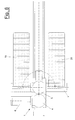
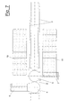
- a preferred embodiment of the device 1 for picking up fibres which comprises a trolley 2, free to translate along a guide, consisting of rails 3.
- a trolley 2 free to translate along a guide, consisting of rails 3.
- two frames 4 and 5 are positioned, which respectively carry two removal arms 6 and 7 canti-levered that indifferently can be made according to one of the known picking-up techniques of the state of the art.
- the servomechanisms 8 and 9 for adjusting the height of the arms 6 and 7 are also schematically illustrated.
- the areas 10 for supporting the bales of fibres are foreseen, to form the rows of bales from which the picking-up is carried out.
- FIG 2 it is shown how the frames 4 and 5 for respectively supporting the removal arms 6 and 7 are arranged in succession along the trolley 2, so that they are respectively free to rotate about the axes 11 and 12, to pass from the position illustrated in the figures, with the two removal arms 6 and 7 on two opposite sides of the trolley 2, to a position in which both of the arms 6 and 7 are on the one side or on the other side of the trolley 2.
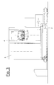
- Figure 3 schematically shows the picking-up apparatuses of a removal arm 6, in particular a reel 13, a support pad 14 and two toothed wheels 15 and 16, respectively arranged on two rotating shafts 17 and 18.
- Figure 4 schematically shows a detail of the device for picking up fibres from bales according to the present invention.
- both of the removal arms 6 and 7 work on the same side of the trolley 2, which displaces translating along the row of bales 19, one of the two arms precedes the other in the passage on the removal surface of the row of bales.
- the device displaces from right to left and the removal arm 6, which precedes in the direction of movement of the device, is at a slightly greater height to that of the removal arm 7 that follows. Necessarily, the relative heights of the two arms invert in the subsequent passage of the device on the row of bales from left to right.
- Figure 5 shows the device 1 for picking up fibres, during a picking-up step in which there is a first row of bales 19, already partially processed during previous passages of the removal arms 6 and 7, on one side of the rails 3, whilst on the other side the arrangement of a second row of bales is in progress.
- Both of the removal arms 6 and 7 work, carrying out one or more passages, on the removal surface of the same row of bales 19, in particular on the densest and previously flattened zones of said first row of bales 19. Consequently, the picking-up carried out is optimal.
- Figure 6 shows the device 1 for picking up fibres, during a second step of the process for picking up fibres according to the present invention.
- the support frame 5 of the removal arm 7 has been made to rotate by 180° about the trolley 2, so that the removal arm 7 rests above said second row of bales 20 during the different passages of the trolley along the rows of bales 19 and 20.
- the removal arms 6 and 7 work, carrying out one or more passages, on the removal surface of the two different rows of bales 19 and 20, but, whilst the removal arm 6 operates on the densest and previously flattened zones of said first row of bales 19, the removal arm 7 operates on the upper surface, not yet levelled, of said second row of bales 20. Consequently, the picking up carried out on said second row of bales 20 may not be constant.
- Figure 7 shows the device for picking up fibres during a third step of the process for picking up fibres according to the present invention.
- the removal arms 6 and 7 work, carrying out one or more passages, respectively on the removal surface of the two different rows of bales 19 and 20, both operating on the densest and previously flattened zones of said rows of bales 19 and 20. Consequently, the picking up carried out on said rows of bales 19 and 20 is optimal.
- the device for picking up fibres is still arranged as shown in figure 7.
- the first row of bales 19 is now in a state of exhaustion.
- the removal arms 6 and 7 work, carrying out one or more passages, respectively on the removal surface of the two different rows of bales 19 and 20, but, whilst the removal arm 7 operates on the densest and previously flattened zones of said second row of bales 20, the removal arm 6 operates on the end portion of said first row of bales 19. Consequently, the picking up carried out on said first row of bales 19 may not be constant.
- the simultaneous picking up on two different rows of bales 19 and 20, one of which in optimal picking-up conditions and the other in potentially inconstant picking-up conditions, allows the possible jumps in picking up of fibres due to surface dishomogeneity of the first row of bales 19 that is running out to be minimized through the mixing of said fibres with those picked up from the previously flattened second row of bales 20.
- Figure 8 shows the device for picking up fibres during a further step of the process for picking up fibres according to the present invention, in a position mirroring the one shown in figure 5.
- the removal arm 6 was made to rotate by 180° around the trolley 2, so as to rest over said second row of bales 20 during the different passages of the trolley along said second row of bales 20.
- both of the removal arms 6 and 7 work, carrying out one or more passages, on the removal surface of the same row of bales 20, in particular on the densest and previously flattened zones of said second row of bales 20. Consequently, the picking up carried out is optimal.
- the position of the device shown in figure 8 perfectly mirrors the one shown in figure 5 and it is clear to the man skilled in the art that the device 1 shall cross subsequent cyclical steps of the process according to the present invention, which shall from time to time be mirror-like or identical to those shown with reference to figures 5-8.
- the steps described in relation to the position of the device 1 for picking up fibres refer to the process for picking up fibres from bales of fibres, according to the present invention, in normal operating conditions.
- the process fore sees picking up fibres from the surface layers of a single row of bales, until the inner layers of the bales are reached. From this moment it is possible to proceed in normal operating conditions, according to the cyclical steps described with reference to figures 5-8.
- the duration of the different processing steps can be varied by controlling the removal speed of the device for picking up fibres according to the present invention. This type of variations can be made by the operator even during the course of a processing step that has already begun, for example to prevent a row of bales finishing before a new row of bales has been arranged on the opposite side.
- the invention should be understood to be applicable irrespective of the type of picking up means adopted, which make use of cutting or pressure reels, pincer means of flocks of fibres or pneumatic picking up means.
Landscapes
- Engineering & Computer Science (AREA)
- Textile Engineering (AREA)
- Preliminary Treatment Of Fibers (AREA)
- Nonwoven Fabrics (AREA)
Applications Claiming Priority (2)
| Application Number | Priority Date | Filing Date | Title |
|---|---|---|---|
| ITMI20040412 | 2004-03-04 | ||
| ITMI20040412 ITMI20040412A1 (it) | 2004-03-04 | 2004-03-04 | Dispositivo e procedimento per il prelievo automatico di fibre da balle di fibre |
Publications (2)
| Publication Number | Publication Date |
|---|---|
| EP1571244A1 true EP1571244A1 (fr) | 2005-09-07 |
| EP1571244B1 EP1571244B1 (fr) | 2007-06-06 |
Family
ID=34746718
Family Applications (1)
| Application Number | Title | Priority Date | Filing Date |
|---|---|---|---|
| EP20050075460 Expired - Lifetime EP1571244B1 (fr) | 2004-03-04 | 2005-02-25 | Dispositif et procédé pour enlever automatiquement des fibres coupées de balles de fibres |
Country Status (4)
| Country | Link |
|---|---|
| EP (1) | EP1571244B1 (fr) |
| DE (1) | DE602005001276T2 (fr) |
| ES (1) | ES2288283T3 (fr) |
| IT (1) | ITMI20040412A1 (fr) |
Cited By (3)
| Publication number | Priority date | Publication date | Assignee | Title |
|---|---|---|---|---|
| ITBS20090208A1 (it) * | 2009-11-16 | 2011-05-17 | Marzoli Spa | Dispositivo e metodo per il prelievo automatico di fibra da balle di fibra in una linea di filatura |
| EP3009538A1 (fr) * | 2014-10-16 | 2016-04-20 | Maschinenfabrik Rieter Ag | Ouvreuse de balles |
| CN113151906A (zh) * | 2021-04-26 | 2021-07-23 | 桐乡市四发机械设备制造有限公司 | 一种取毛机 |
Citations (5)
| Publication number | Priority date | Publication date | Assignee | Title |
|---|---|---|---|---|
| US4514881A (en) * | 1982-03-09 | 1985-05-07 | Hergeth Hollingsworth, Gmbh | Method and apparatus for reducing fiber bales |
| US4566152A (en) * | 1982-05-04 | 1986-01-28 | Rieter Machine Works | Method of removing flocks from fiber bales |
| US4712275A (en) * | 1983-09-26 | 1987-12-15 | Trutzschler Gmbh & Co. Kg | Method for driving a bale opener |
| US4888857A (en) * | 1987-09-11 | 1989-12-26 | Hergeth Hollingsworth Gmbh | Apparatus for removing fiber material accumulations, in particular from bales of spinning material |
| US5175909A (en) * | 1989-02-03 | 1993-01-05 | Hergeth Hollingsworth Gmbh | Suction device |
-
2004
- 2004-03-04 IT ITMI20040412 patent/ITMI20040412A1/it unknown
-
2005
- 2005-02-25 DE DE602005001276T patent/DE602005001276T2/de not_active Expired - Lifetime
- 2005-02-25 EP EP20050075460 patent/EP1571244B1/fr not_active Expired - Lifetime
- 2005-02-25 ES ES05075460T patent/ES2288283T3/es not_active Expired - Lifetime
Patent Citations (5)
| Publication number | Priority date | Publication date | Assignee | Title |
|---|---|---|---|---|
| US4514881A (en) * | 1982-03-09 | 1985-05-07 | Hergeth Hollingsworth, Gmbh | Method and apparatus for reducing fiber bales |
| US4566152A (en) * | 1982-05-04 | 1986-01-28 | Rieter Machine Works | Method of removing flocks from fiber bales |
| US4712275A (en) * | 1983-09-26 | 1987-12-15 | Trutzschler Gmbh & Co. Kg | Method for driving a bale opener |
| US4888857A (en) * | 1987-09-11 | 1989-12-26 | Hergeth Hollingsworth Gmbh | Apparatus for removing fiber material accumulations, in particular from bales of spinning material |
| US5175909A (en) * | 1989-02-03 | 1993-01-05 | Hergeth Hollingsworth Gmbh | Suction device |
Cited By (6)
| Publication number | Priority date | Publication date | Assignee | Title |
|---|---|---|---|---|
| ITBS20090208A1 (it) * | 2009-11-16 | 2011-05-17 | Marzoli Spa | Dispositivo e metodo per il prelievo automatico di fibra da balle di fibra in una linea di filatura |
| EP2322701A1 (fr) | 2009-11-16 | 2011-05-18 | Marzoli S.P.A. | Dispositif et procédé pour la capture automatique de fibres d'une balle de fibres sur une chaîne de filature |
| EP3009538A1 (fr) * | 2014-10-16 | 2016-04-20 | Maschinenfabrik Rieter Ag | Ouvreuse de balles |
| CN105523387A (zh) * | 2014-10-16 | 2016-04-27 | 里特机械公司 | 拆包机 |
| US10190238B2 (en) | 2014-10-16 | 2019-01-29 | Maschinenfabrik Rieter Ag | Bale opener |
| CN113151906A (zh) * | 2021-04-26 | 2021-07-23 | 桐乡市四发机械设备制造有限公司 | 一种取毛机 |
Also Published As
| Publication number | Publication date |
|---|---|
| DE602005001276D1 (de) | 2007-07-19 |
| DE602005001276T2 (de) | 2008-01-31 |
| EP1571244B1 (fr) | 2007-06-06 |
| ES2288283T3 (es) | 2008-01-01 |
| ITMI20040412A1 (it) | 2004-06-04 |
Similar Documents
| Publication | Publication Date | Title |
|---|---|---|
| US4888857A (en) | Apparatus for removing fiber material accumulations, in particular from bales of spinning material | |
| EP1591427A1 (fr) | Une station de travaille pour machiner des feuilles de verre, de marbre ou materiau similaire avec un système de chargement automatique des feuilles | |
| US4076159A (en) | Breaking flat glass into cullet | |
| US4463483A (en) | Fabric napping apparatus | |
| EP1571244B1 (fr) | Dispositif et procédé pour enlever automatiquement des fibres coupées de balles de fibres | |
| ITMI940813A1 (it) | Dispositivo per il riempimento di vasi con nastro di carda, per esempio cotone, fibre artificiali o simili in una macchine per filanda per esempio stiratoio | |
| CN106975966A (zh) | 长棒料定长输送与收集装置 | |
| CN215514327U (zh) | 一种便于调节的贴膜机 | |
| JPH0235050B2 (fr) | ||
| CN204769563U (zh) | 自清理清辊装置及除麻丝机、不间断除麻丝机组 | |
| KR20020062167A (ko) | 조방기의 보빈 교환 장치 | |
| CN100422407C (zh) | 适用于往复式抓棉机的抓棉器机构 | |
| CN110950190A (zh) | 自动铺绳机 | |
| CN108754975B (zh) | 一种用于纺织物的自动剪毛系统及其剪毛加工方法 | |
| CN212686782U (zh) | 一种络筒输送系统 | |
| JP3210430B2 (ja) | 繊維俵から繊維タフトを分離する開綿装置 | |
| EP1580150A1 (fr) | Appareil de chargement et déchargement d'éléments plats pour des machines traitant des matériaux plans | |
| JP3215506B2 (ja) | 木綿、化学繊維などの如き原料繊維俵から繊維塊を取り出す方法及び装置 | |
| CN222833559U (zh) | 一种织针自动摆放设备 | |
| CN223765694U (zh) | 一种超细纤维拖把布生产包装设备 | |
| CN107487486B (zh) | 一种镜片上下装盒机 | |
| EP1088925A1 (fr) | Appareil et procédé pour transférer automatiquement des articles tubulaires, en particulier des collants, à une machine à coudre adaptée à la fermeture de ces articles à une de leurs extrémités axiales | |
| CN207597027U (zh) | 一种纺纱机用纱筒传输装置 | |
| CN222345694U (zh) | 丝瓜络鞋垫生产的切割平台 | |
| JPH07216663A (ja) | 木綿、化学繊維などからなる繊維俵を繊維俵取り出し機械に沿って1列に準備する方法及び装置 |
Legal Events
| Date | Code | Title | Description |
|---|---|---|---|
| PUAI | Public reference made under article 153(3) epc to a published international application that has entered the european phase |
Free format text: ORIGINAL CODE: 0009012 |
|
| AK | Designated contracting states |
Kind code of ref document: A1 Designated state(s): AT BE BG CH CY CZ DE DK EE ES FI FR GB GR HU IE IS IT LI LT LU MC NL PL PT RO SE SI SK TR |
|
| AX | Request for extension of the european patent |
Extension state: AL BA HR LV MK YU |
|
| 17P | Request for examination filed |
Effective date: 20060215 |
|
| AKX | Designation fees paid |
Designated state(s): CH DE ES IT LI |
|
| GRAP | Despatch of communication of intention to grant a patent |
Free format text: ORIGINAL CODE: EPIDOSNIGR1 |
|
| GRAS | Grant fee paid |
Free format text: ORIGINAL CODE: EPIDOSNIGR3 |
|
| GRAA | (expected) grant |
Free format text: ORIGINAL CODE: 0009210 |
|
| AK | Designated contracting states |
Kind code of ref document: B1 Designated state(s): CH DE ES IT LI |
|
| REG | Reference to a national code |
Ref country code: CH Ref legal event code: EP |
|
| REF | Corresponds to: |
Ref document number: 602005001276 Country of ref document: DE Date of ref document: 20070719 Kind code of ref document: P |
|
| REG | Reference to a national code |
Ref country code: CH Ref legal event code: NV Representative=s name: A. BRAUN, BRAUN, HERITIER, ESCHMANN AG PATENTANWAE |
|
| REG | Reference to a national code |
Ref country code: ES Ref legal event code: FG2A Ref document number: 2288283 Country of ref document: ES Kind code of ref document: T3 |
|
| PLBE | No opposition filed within time limit |
Free format text: ORIGINAL CODE: 0009261 |
|
| STAA | Information on the status of an ep patent application or granted ep patent |
Free format text: STATUS: NO OPPOSITION FILED WITHIN TIME LIMIT |
|
| 26N | No opposition filed |
Effective date: 20080307 |
|
| REG | Reference to a national code |
Ref country code: CH Ref legal event code: PFA Owner name: MARZOLI S.P.A. Free format text: MARZOLI S.P.A.#VIA S. ALBERTO 2#25036 PALAZZOLO SULL'OGLIO, BRESCIA (IT) -TRANSFER TO- MARZOLI S.P.A.#VIA S. ALBERTO 2#25036 PALAZZOLO SULL'OGLIO, BRESCIA (IT) |
|
| REG | Reference to a national code |
Ref country code: CH Ref legal event code: PCAR Free format text: NEW ADDRESS: HOLBEINSTRASSE 36-38, 4051 BASEL (CH) |
|
| PGFP | Annual fee paid to national office [announced via postgrant information from national office to epo] |
Ref country code: IT Payment date: 20150213 Year of fee payment: 11 |
|
| PG25 | Lapsed in a contracting state [announced via postgrant information from national office to epo] |
Ref country code: IT Free format text: LAPSE BECAUSE OF NON-PAYMENT OF DUE FEES Effective date: 20160225 |
|
| PGFP | Annual fee paid to national office [announced via postgrant information from national office to epo] |
Ref country code: ES Payment date: 20230301 Year of fee payment: 19 Ref country code: CH Payment date: 20230307 Year of fee payment: 19 |
|
| PGFP | Annual fee paid to national office [announced via postgrant information from national office to epo] |
Ref country code: DE Payment date: 20230216 Year of fee payment: 19 |
|
| P01 | Opt-out of the competence of the unified patent court (upc) registered |
Effective date: 20230523 |
|
| REG | Reference to a national code |
Ref country code: DE Ref legal event code: R119 Ref document number: 602005001276 Country of ref document: DE |
|
| REG | Reference to a national code |
Ref country code: CH Ref legal event code: PL |
|
| PG25 | Lapsed in a contracting state [announced via postgrant information from national office to epo] |
Ref country code: CH Free format text: LAPSE BECAUSE OF NON-PAYMENT OF DUE FEES Effective date: 20240229 |
|
| PG25 | Lapsed in a contracting state [announced via postgrant information from national office to epo] |
Ref country code: CH Free format text: LAPSE BECAUSE OF NON-PAYMENT OF DUE FEES Effective date: 20240229 |
|
| PG25 | Lapsed in a contracting state [announced via postgrant information from national office to epo] |
Ref country code: DE Free format text: LAPSE BECAUSE OF NON-PAYMENT OF DUE FEES Effective date: 20240903 |
|
| PG25 | Lapsed in a contracting state [announced via postgrant information from national office to epo] |
Ref country code: DE Free format text: LAPSE BECAUSE OF NON-PAYMENT OF DUE FEES Effective date: 20240903 |
|
| REG | Reference to a national code |
Ref country code: ES Ref legal event code: FD2A Effective date: 20250401 |
|
| PG25 | Lapsed in a contracting state [announced via postgrant information from national office to epo] |
Ref country code: ES Free format text: LAPSE BECAUSE OF NON-PAYMENT OF DUE FEES Effective date: 20240226 |