EP1571280A2 - Charnière - Google Patents
Charnière Download PDFInfo
- Publication number
- EP1571280A2 EP1571280A2 EP05251151A EP05251151A EP1571280A2 EP 1571280 A2 EP1571280 A2 EP 1571280A2 EP 05251151 A EP05251151 A EP 05251151A EP 05251151 A EP05251151 A EP 05251151A EP 1571280 A2 EP1571280 A2 EP 1571280A2
- Authority
- EP
- European Patent Office
- Prior art keywords
- hinge
- main body
- body portion
- clamping block
- knuckles
- Prior art date
- Legal status (The legal status is an assumption and is not a legal conclusion. Google has not performed a legal analysis and makes no representation as to the accuracy of the status listed.)
- Withdrawn
Links
- 230000033001 locomotion Effects 0.000 description 2
- 238000000034 method Methods 0.000 description 2
- HCHKCACWOHOZIP-UHFFFAOYSA-N Zinc Chemical compound [Zn] HCHKCACWOHOZIP-UHFFFAOYSA-N 0.000 description 1
- 230000008933 bodily movement Effects 0.000 description 1
- 238000004512 die casting Methods 0.000 description 1
- 230000005484 gravity Effects 0.000 description 1
- 239000000463 material Substances 0.000 description 1
- 229920003002 synthetic resin Polymers 0.000 description 1
- 239000000057 synthetic resin Substances 0.000 description 1
- 229920011532 unplasticized polyvinyl chloride Polymers 0.000 description 1
- 239000011701 zinc Substances 0.000 description 1
- 229910052725 zinc Inorganic materials 0.000 description 1
Images

Classifications
-
- E—FIXED CONSTRUCTIONS
- E05—LOCKS; KEYS; WINDOW OR DOOR FITTINGS; SAFES
- E05D—HINGES OR SUSPENSION DEVICES FOR DOORS, WINDOWS OR WINGS
- E05D7/00—Hinges or pivots of special construction
- E05D7/04—Hinges adjustable relative to the wing or the frame
- E05D7/0415—Hinges adjustable relative to the wing or the frame with adjusting drive means
- E05D7/0423—Screw-and-nut mechanisms
-
- E—FIXED CONSTRUCTIONS
- E05—LOCKS; KEYS; WINDOW OR DOOR FITTINGS; SAFES
- E05D—HINGES OR SUSPENSION DEVICES FOR DOORS, WINDOWS OR WINGS
- E05D3/00—Hinges with pins
- E05D3/02—Hinges with pins with one pin
- E05D2003/025—Hinges with pins with one pin having three knuckles
-
- E—FIXED CONSTRUCTIONS
- E05—LOCKS; KEYS; WINDOW OR DOOR FITTINGS; SAFES
- E05D—HINGES OR SUSPENSION DEVICES FOR DOORS, WINDOWS OR WINGS
- E05D7/00—Hinges or pivots of special construction
- E05D7/04—Hinges adjustable relative to the wing or the frame
- E05D2007/0469—Hinges adjustable relative to the wing or the frame in an axial direction
-
- E—FIXED CONSTRUCTIONS
- E05—LOCKS; KEYS; WINDOW OR DOOR FITTINGS; SAFES
- E05Y—INDEXING SCHEME ASSOCIATED WITH SUBCLASSES E05D AND E05F, RELATING TO CONSTRUCTION ELEMENTS, ELECTRIC CONTROL, POWER SUPPLY, POWER SIGNAL OR TRANSMISSION, USER INTERFACES, MOUNTING OR COUPLING, DETAILS, ACCESSORIES, AUXILIARY OPERATIONS NOT OTHERWISE PROVIDED FOR, APPLICATION THEREOF
- E05Y2900/00—Application of doors, windows, wings or fittings thereof
- E05Y2900/10—Application of doors, windows, wings or fittings thereof for buildings or parts thereof
- E05Y2900/13—Type of wing
- E05Y2900/132—Doors
Definitions
- This invention relates to adjustable hinges, primarily, but not exclusively, for use with UPVC doors.
- Doors are conventionally fitted to door frames by the use of at least two sets of hinges.
- the alignment of a door within a frame utilising conventional non-adjustable hinges is a repetitious and time consuming process often involving the removal, adjustment, and replacement of the door within the frame a plurality of times.
- a hinge consists of a hinge body which is attached to the door frame (although could be attached to the door in some circumstances) and a hinge leaf pivotally mounted to the hinge body and conventionally fixed to the door (although where the body is fixed to the door the leaf will be fixed to the frame).
- a hinge body which is attached to the door frame (although could be attached to the door in some circumstances) and a hinge leaf pivotally mounted to the hinge body and conventionally fixed to the door (although where the body is fixed to the door the leaf will be fixed to the frame).
- a known height adjustable hinge includes a two-part body, a first part of which carries the leaf through the intermediary of a pivot pin, and the second part of which is secured to the door frame by screws, bolts or the like, and clamps the first body part to the door frame. Height adjustment is provided by a generally vertically extending screw, in screw-threaded engagement with the first part of the body, and abutting an end surface of the second part of the body which is positioned at an uppermost end of the second body part in use.
- Height adjustment is achieved, after fitting the door to the door frame, by slackening the fixing of the second body part to the door frame to slacken the clamping of the first body part, adjustment of the screw relative to the first body part to adjust the vertical position of the first body part relative to the second body part, and then re-tightening the fastening of the second body part to clamp the first body part in position relative to the door frame.
- the provision of a single screw in threaded engagement with the first body part and bearing against the upper end of the second body part allows the screw to be screwed "downwardly" to lift the first body part relative to the second body part and the door frame, but relies upon gravity to move the first body part for downward adjustment relative to the second body part.
- the adjustment of the first body part relative to the second body part is not a positive adjustment, and given that two or more hinges must be adjusted simultaneously, adjustment can be problematic.
- the fitter may only partially slacken the fixing of the respective second body parts to the door frame and for downward adjustment the grip between the first and second body parts may be such that it is necessary to hammer the door or the hinge first body parts downwardly thereby risking damage to the door and/or hinges.
- a height adjustable hinge comprising a hinge body, a hinge leaf pivotally mounted to the hinge body, the hinge body including a main body portion carrying said leaf, and a clamping block for securing the main body portion to a door frame or a door in use, the hinge body including screw adjustment means linking the main body portion and the clamping block to permit the position of the main body portion relative to the clamping block to be positively adjusted in both opposite directions.
- said screw adjustment means includes first and second adjustment screws generally aligned with one another in the direction of adjustment of the main body portion relative to the clamping block, each of said first and second screws being in screw-threaded engagement with respective opposite end regions of the clamping block and each having a head which can bear against a surface of the main body portion remote from the clamping block.
- the heads of said first and second adjustment screws are received within recesses in opposite ends of the main body portion respectively.
- said main body portion carries screw adjusters for adjusting the position of the hinge leaf relative to said main body portion in a direction at right angles to the adjustment of the main body portion relative to the clamping block.
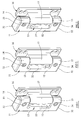
- the height adjustable hinge includes a hinge body 11 comprising a main body portion 12 and a clamping block 13 (to be described in more detail hereinafter).
- the main body portion 12 of the hinge body includes, at opposite ends thereof respectively, first and second parallel knuckles 14, 15 between which is positioned a hollow cylindrical sleeve 17 forming part of the hinge leaf 16.
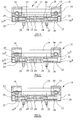
- a pivot pin 18 ( Figure 5) is received at its ends in passages in the knuckles 14, 15 respectively, and extends through the sleeve 17 to mount the leaf 16 for pivotal movement about the axis of the pin 18 on the main body portion 12 of the hinge body.
- the sleeve 17 has bearing bushes adjacent its ends which engage the pivot pin 18, the bearing bushes including end flanges interposed between the axial ends of the sleeve 17 and the abutting faces of the knuckles 14, 15.
- hinges of the kind illustrated in the drawings serve to mount a door to a door frame, each hinge body 11 being secured to the door frame through the intermediary of its respective clamping block 13 and each hinge leaf 16 being secured to the door.
- the hinges are arranged with their pivot pin axes aligned and vertical.
- the main body portion 12, the clamping block 13, and the leaf 16 are all conveniently formed as zinc die-castings, but can be formed by other techniques, from other materials, as appropriate.
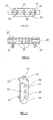
- the face of the main body portion 12 remote from the knuckles 14, 15 is planar and is formed with a centrally disposed elongate slot 21 which penetrates the region of the body portion 12 between the knuckles 14, 15, and penetrates also the base of recessed regions 14 a , 15 a ( Figure 4 and Figure 7) within the knuckles 14, 15 respectively.
- the clamping block 13 is elongate, but is of a length less than the length of the slot 21 in the main body portion 12.
- the width of the clamping block 13 is such that it can extend slidably within the slot 21, and adjacent its outer face (in use) the block 13 has oppositely directed integral wings 22 which can overlie the surface of the main body portion 12 between the knuckles 14, 15 while the remainder of the block 13 extends within the slot 21.
- the wings 22 are centrally disposed along the length of the block 13, and the length of the wings 22 is less than the spacing between the knuckles 14, 15 by an amount equal to the amount by which the length of the block 13 is less than the length of the slot 21.
- the rear face of the block 13 is provided within integral protruding posts 23 which are received in use in pre-drilled holes in the door frame to facilitate accurate mounting of the clamping blocks 13 to the door frame.
- Each of the clamping blocks has three parallel bores 24 extending therethrough, the bores being countersunk at the outer face of the block 13, and being intended to receive clamping screws or bolts for rigidly securing the block 13 to the door frame.
- firstly the hinge leaf 16 is detached by withdrawing the pivot pin 18 to expose the bores 24 of the block 13.
- the block 13 is, at this time, slidably received within the slot 21 of the main portion 12, and is secured to the main body portion 12 in a longitudinally adjustable manner, by means of first and second adjustment screws 25, 26.
- the screws 25, 26 are longitudinally aligned, and have their shanks in screw-threaded engagement with respective threaded bores 27, 28 extending longitudinally into the end regions of the block 13.
- Each screw 25, 26 has its head 25 a , 26 a received within a respective recess 29, 31 in the end face of its respective knuckle 14, 15 and normally each screw 25, 26 is tightened so that its head bears against the base of the respective recess 29, 31.
- the hinge body 11 is presented to the door frame and the posts 23 are introduced into the respective apertures in the door frame. Fixing screws or bolts are inserted through the bores 24 and are tightened to clamp the clamp block 13 against the door frame.
- the spacing between the underface of the wings 22 and the rear face of the block 13 is slightly less than the thickness of the main body portion 12 between the knuckles 14, 15 so that tightening of the fixing screws or bolts of the clamping block causes the wings 22 to bear against the front face of the main body portion 12 between the knuckles, and thus to clamp the body portion 12 against the door frame.
- each hinge leaf 16 is reassembled between the knuckles 14, 15 of the respective body, the respective pin 18 being reintroduced to provide the pivotal interconnection between the hinge leaf and the hinge body.
- each block 13 is arranged in a central position relative to the respective main body portion 12 (as shown in Figure 1, Figure 4, and Figure 12).
- Figures 13 and 14 illustrate adjustment of the hinge body in the opposite direction from the central position.
- the screw 26 a is slackened by unscrewing it from the block 13 to provide a clearance between the head 26 a and the base of the recess 31 in the knuckle 15.
- the screw 25 is then tightened to push the body portion 12 downwardly relative to the block 13 and the door frame to take up the clearance between the head 26 a and the base of the recess 31. It will be recognised however that if the clamp block 13 was slackened sufficiently then the weight of the door would cause the movement of the body portion 12 relative to the block 13 as the screw 26 a is unscrewed relative to the block 13.
- each hinge main body portion 12 After re-positioning of each hinge main body portion 12 relative to its respective block 13 and the door frame, the fastenings of the clamping blocks 13 are re-tightened to clamp the main body portions 12 against the door frame.
- Decorative moulded synthetic resin caps 32 are clipped into engagement with the end faces of the knuckles 14, 15 respectively to close the recesses 29, 31 and also to close the ends of the bores in the knuckles 14, 15 through which the pivot pin 18 extends.
- the pivot pin 18 is mounted within the knuckles 14, 15 by means of screw adjusters 33, 34 of any convenient form which permit bodily movement of the pivot pin 18 transversely relative to its longitudinal axis to adjust the positioning in a "fore and aft" direction of the hinge leaf 16 relative to the hinge body 11. It will be understood therefore that the passages in the knuckles 14, 15 within which the pivot pin 18 extends are elongate, rather than circular, in transverse cross-section and the pin is located therein by the screw adjusters 33, 34 which provide a mode of adjustment of the door relative to the door frame at right-angles to the height adjustment provided by the screws 25, 26.
- the screw adjusters 33, 34 can be of any convenient form, for example as shown in British Patent 2356222, or in British Patent 2276199.
- the screw adjusters 33, 34 have cross-head screwdriver recesses therein, and the screws 25, 26 can have similar recesses, or, as desired, can have cross-head screwdriver slots, or "Allen-key" recesses.
Landscapes
- Hinges (AREA)
- Engineering & Computer Science (AREA)
- Mechanical Engineering (AREA)
Applications Claiming Priority (2)
| Application Number | Priority Date | Filing Date | Title |
|---|---|---|---|
| GB0404962 | 2004-03-04 | ||
| GB0404962A GB0404962D0 (en) | 2004-03-04 | 2004-03-04 | Hinge |
Publications (2)
| Publication Number | Publication Date |
|---|---|
| EP1571280A2 true EP1571280A2 (fr) | 2005-09-07 |
| EP1571280A3 EP1571280A3 (fr) | 2006-06-14 |
Family
ID=32088759
Family Applications (1)
| Application Number | Title | Priority Date | Filing Date |
|---|---|---|---|
| EP05251151A Withdrawn EP1571280A3 (fr) | 2004-03-04 | 2005-02-26 | Charnière |
Country Status (2)
| Country | Link |
|---|---|
| EP (1) | EP1571280A3 (fr) |
| GB (1) | GB0404962D0 (fr) |
Cited By (2)
| Publication number | Priority date | Publication date | Assignee | Title |
|---|---|---|---|---|
| CN102287102A (zh) * | 2010-06-15 | 2011-12-21 | 家居安全组有限公司 | 铰链 |
| EP3059365A1 (fr) * | 2015-02-25 | 2016-08-24 | Deal S.r.l. | Dispositif de charnière compact |
Family Cites Families (5)
| Publication number | Priority date | Publication date | Assignee | Title |
|---|---|---|---|---|
| DE2515335A1 (de) * | 1975-04-09 | 1976-10-21 | Haps & Sohn Metallwarenfabrik | Tuerband |
| US5339493A (en) * | 1992-10-30 | 1994-08-23 | Macintyre Robert J | Adjustable hinge |
| US5713105A (en) * | 1996-09-20 | 1998-02-03 | Lawrence Brothers Inc. | Adjustable hinge |
| GB2356222B (en) * | 1999-11-12 | 2003-08-27 | Paddock Fabrications Ltd | Adjustable hinge |
| GB0110359D0 (en) * | 2001-04-27 | 2001-06-20 | Window Fab & Fixing Supplies | Hinge |
-
2004
- 2004-03-04 GB GB0404962A patent/GB0404962D0/en not_active Ceased
-
2005
- 2005-02-26 EP EP05251151A patent/EP1571280A3/fr not_active Withdrawn
Cited By (6)
| Publication number | Priority date | Publication date | Assignee | Title |
|---|---|---|---|---|
| CN102287102A (zh) * | 2010-06-15 | 2011-12-21 | 家居安全组有限公司 | 铰链 |
| GB2481371A (en) * | 2010-06-15 | 2011-12-28 | Grouphomesafe Ltd | Adjustable hinge |
| GB2481371B (en) * | 2010-06-15 | 2016-06-08 | Grouphomesafe Ltd | Hinges |
| CN102287102B (zh) * | 2010-06-15 | 2016-08-03 | 时代家居安全有限公司 | 铰链 |
| EP3059365A1 (fr) * | 2015-02-25 | 2016-08-24 | Deal S.r.l. | Dispositif de charnière compact |
| ITUB20150334A1 (it) * | 2015-02-25 | 2016-08-25 | Deal S R L | Dispositivo a cerniera compatto |
Also Published As
| Publication number | Publication date |
|---|---|
| GB0404962D0 (en) | 2004-04-07 |
| EP1571280A3 (fr) | 2006-06-14 |
Similar Documents
| Publication | Publication Date | Title |
|---|---|---|
| US9416573B2 (en) | Door hinge | |
| EP0950786B1 (fr) | Procédé pour fabriquer un système de fixation d'un vantail de porte | |
| CA2301950C (fr) | Charnieres a talon reglable | |
| JP7171701B2 (ja) | スライドドア用ガラス板固定装置 | |
| EP3029238B1 (fr) | Ferrure d'angle dotée d'une plage de serrage réglable | |
| EP0285229B1 (fr) | Charnière réglable, en particulier pour portes | |
| US11046254B2 (en) | Device for raising roof bars | |
| CA2570091C (fr) | Systeme et procede de fixation par charniere | |
| EP1571280A2 (fr) | Charnière | |
| CN203947930U (zh) | 推拉门窗剪式可调随动滚轮 | |
| EP2882918A1 (fr) | Structure de paumelle pour portes, fenêtres et analogues | |
| CA2999762C (fr) | Charniere reglable pour eliminer le calage | |
| EP2458122A1 (fr) | Charnière pour portes ou fenêtres | |
| JP3730746B2 (ja) | 蝶番 | |
| DE3546253C2 (fr) | ||
| EP2172610B1 (fr) | Elément de fixation d'une penture | |
| EP1061219A1 (fr) | Charnière pour cadres | |
| EP1243214B1 (fr) | Charnière et panneau de séparation, en particulier cabine de douche avec charnière pour permettre la rotation d'une porte en verre | |
| EP3029240A1 (fr) | Ferrure d'angle dotée d'une plage de réglage variable | |
| EP3029227B2 (fr) | Ferrure dotée d'une plage de serrage réglable | |
| CH697365B1 (de) | Mehrdimensional verstellbares Türband. | |
| EP3181786A1 (fr) | Élément de charnière d'ouvrant | |
| CN100439644C (zh) | 用于门、窗和类似部件的铰链 | |
| EP4321715B1 (fr) | Charnière de porte ou de fenêtre réglable à réglage latéral amélioré | |
| EP1514000B1 (fr) | Systeme pour assembler deux elements dont un au moins comprend deux cavites |
Legal Events
| Date | Code | Title | Description |
|---|---|---|---|
| PUAI | Public reference made under article 153(3) epc to a published international application that has entered the european phase |
Free format text: ORIGINAL CODE: 0009012 |
|
| AK | Designated contracting states |
Kind code of ref document: A2 Designated state(s): AT BE BG CH CY CZ DE DK EE ES FI FR GB GR HU IE IS IT LI LT LU MC NL PL PT RO SE SI SK TR |
|
| AX | Request for extension of the european patent |
Extension state: AL BA HR LV MK YU |
|
| PUAL | Search report despatched |
Free format text: ORIGINAL CODE: 0009013 |
|
| AK | Designated contracting states |
Kind code of ref document: A3 Designated state(s): AT BE BG CH CY CZ DE DK EE ES FI FR GB GR HU IE IS IT LI LT LU MC NL PL PT RO SE SI SK TR |
|
| AX | Request for extension of the european patent |
Extension state: AL BA HR LV MK YU |
|
| AKX | Designation fees paid | ||
| REG | Reference to a national code |
Ref country code: DE Ref legal event code: 8566 |
|
| STAA | Information on the status of an ep patent application or granted ep patent |
Free format text: STATUS: THE APPLICATION IS DEEMED TO BE WITHDRAWN |
|
| 18D | Application deemed to be withdrawn |
Effective date: 20061215 |