EP1571429B1 - Dispositif indicateur de la charge à l'essieu. - Google Patents
Dispositif indicateur de la charge à l'essieu. Download PDFInfo
- Publication number
- EP1571429B1 EP1571429B1 EP04028930.8A EP04028930A EP1571429B1 EP 1571429 B1 EP1571429 B1 EP 1571429B1 EP 04028930 A EP04028930 A EP 04028930A EP 1571429 B1 EP1571429 B1 EP 1571429B1
- Authority
- EP
- European Patent Office
- Prior art keywords
- calibration
- level
- axle
- ride level
- area
- Prior art date
- Legal status (The legal status is an assumption and is not a legal conclusion. Google has not performed a legal analysis and makes no representation as to the accuracy of the status listed.)
- Expired - Lifetime
Links
Images


Classifications
-
- G—PHYSICS
- G01—MEASURING; TESTING
- G01G—WEIGHING
- G01G19/00—Weighing apparatus or methods adapted for special purposes not provided for in the preceding groups
- G01G19/08—Weighing apparatus or methods adapted for special purposes not provided for in the preceding groups for incorporation in vehicles
- G01G19/10—Weighing apparatus or methods adapted for special purposes not provided for in the preceding groups for incorporation in vehicles having fluid weight-sensitive devices
-
- B—PERFORMING OPERATIONS; TRANSPORTING
- B60—VEHICLES IN GENERAL
- B60G—VEHICLE SUSPENSION ARRANGEMENTS
- B60G17/00—Resilient suspensions having means for adjusting the spring or vibration-damper characteristics, for regulating the distance between a supporting surface and a sprung part of vehicle or for locking suspension during use to meet varying vehicular or surface conditions, e.g. due to speed or load
- B60G17/015—Resilient suspensions having means for adjusting the spring or vibration-damper characteristics, for regulating the distance between a supporting surface and a sprung part of vehicle or for locking suspension during use to meet varying vehicular or surface conditions, e.g. due to speed or load the regulating means comprising electric or electronic elements
- B60G17/0152—Resilient suspensions having means for adjusting the spring or vibration-damper characteristics, for regulating the distance between a supporting surface and a sprung part of vehicle or for locking suspension during use to meet varying vehicular or surface conditions, e.g. due to speed or load the regulating means comprising electric or electronic elements characterised by the action on a particular type of suspension unit
- B60G17/0155—Resilient suspensions having means for adjusting the spring or vibration-damper characteristics, for regulating the distance between a supporting surface and a sprung part of vehicle or for locking suspension during use to meet varying vehicular or surface conditions, e.g. due to speed or load the regulating means comprising electric or electronic elements characterised by the action on a particular type of suspension unit pneumatic unit
-
- B—PERFORMING OPERATIONS; TRANSPORTING
- B60—VEHICLES IN GENERAL
- B60G—VEHICLE SUSPENSION ARRANGEMENTS
- B60G17/00—Resilient suspensions having means for adjusting the spring or vibration-damper characteristics, for regulating the distance between a supporting surface and a sprung part of vehicle or for locking suspension during use to meet varying vehicular or surface conditions, e.g. due to speed or load
- B60G17/02—Spring characteristics, e.g. mechanical springs and mechanical adjusting means
- B60G17/04—Spring characteristics, e.g. mechanical springs and mechanical adjusting means fluid spring characteristics
- B60G17/052—Pneumatic spring characteristics
- B60G17/0521—Pneumatic spring characteristics the spring having a flexible wall
-
- G—PHYSICS
- G01—MEASURING; TESTING
- G01G—WEIGHING
- G01G23/00—Auxiliary devices for weighing apparatus
- G01G23/01—Testing or calibrating of weighing apparatus
-
- B—PERFORMING OPERATIONS; TRANSPORTING
- B60—VEHICLES IN GENERAL
- B60G—VEHICLE SUSPENSION ARRANGEMENTS
- B60G2202/00—Indexing codes relating to the type of spring, damper or actuator
- B60G2202/10—Type of spring
- B60G2202/15—Fluid spring
- B60G2202/152—Pneumatic spring
-
- B—PERFORMING OPERATIONS; TRANSPORTING
- B60—VEHICLES IN GENERAL
- B60G—VEHICLE SUSPENSION ARRANGEMENTS
- B60G2300/00—Indexing codes relating to the type of vehicle
- B60G2300/02—Trucks; Load vehicles
- B60G2300/026—Heavy duty trucks
- B60G2300/0262—Multi-axle trucks
-
- B—PERFORMING OPERATIONS; TRANSPORTING
- B60—VEHICLES IN GENERAL
- B60G—VEHICLE SUSPENSION ARRANGEMENTS
- B60G2300/00—Indexing codes relating to the type of vehicle
- B60G2300/04—Trailers
- B60G2300/042—Semi-trailers
-
- B—PERFORMING OPERATIONS; TRANSPORTING
- B60—VEHICLES IN GENERAL
- B60G—VEHICLE SUSPENSION ARRANGEMENTS
- B60G2400/00—Indexing codes relating to detected, measured or calculated conditions or factors
- B60G2400/25—Stroke; Height; Displacement
- B60G2400/252—Stroke; Height; Displacement vertical
-
- B—PERFORMING OPERATIONS; TRANSPORTING
- B60—VEHICLES IN GENERAL
- B60G—VEHICLE SUSPENSION ARRANGEMENTS
- B60G2400/00—Indexing codes relating to detected, measured or calculated conditions or factors
- B60G2400/50—Pressure
- B60G2400/51—Pressure in suspension unit
- B60G2400/512—Pressure in suspension unit in spring
- B60G2400/5122—Fluid spring
- B60G2400/51222—Pneumatic
-
- B—PERFORMING OPERATIONS; TRANSPORTING
- B60—VEHICLES IN GENERAL
- B60G—VEHICLE SUSPENSION ARRANGEMENTS
- B60G2400/00—Indexing codes relating to detected, measured or calculated conditions or factors
- B60G2400/60—Load
-
- B—PERFORMING OPERATIONS; TRANSPORTING
- B60—VEHICLES IN GENERAL
- B60G—VEHICLE SUSPENSION ARRANGEMENTS
- B60G2600/00—Indexing codes relating to particular elements, systems or processes used on suspension systems or suspension control systems
- B60G2600/70—Computer memory; Data storage, e.g. maps for adaptive control
-
- B—PERFORMING OPERATIONS; TRANSPORTING
- B60—VEHICLES IN GENERAL
- B60G—VEHICLE SUSPENSION ARRANGEMENTS
- B60G2800/00—Indexing codes relating to the type of movement or to the condition of the vehicle and to the end result to be achieved by the control action
- B60G2800/70—Estimating or calculating vehicle parameters or state variables
- B60G2800/702—Improving accuracy of a sensor signal
-
- B—PERFORMING OPERATIONS; TRANSPORTING
- B60—VEHICLES IN GENERAL
- B60G—VEHICLE SUSPENSION ARRANGEMENTS
- B60G2800/00—Indexing codes relating to the type of movement or to the condition of the vehicle and to the end result to be achieved by the control action
- B60G2800/90—System Controller type
- B60G2800/91—Suspension Control
- B60G2800/914—Height Control System
Definitions
- the invention relates to a device for the display [and the control] of the axle load of vehicles according to the preamble of patent claim 1.
- Such axle load indicating device is known from EP 0 666 468 B1 known (hereinafter referred to as D1).
- the vehicle spring units z. B. designed as a pneumatic displacement units whose pressure to maintain a loading independent predetermined ground clearance is load-dependent controllable, the Verdrängeraggregaten associated pressure transducer and / or the spring assemblies associated displacement sensor for controlling the axle load indicator are provided.
- the display is performed using a computer electronics based on a predetermined correlation between pressure or stroke on the one hand and axle load on the other.
- the displayed value can be changed by actuating an adjustment handle; in such a change, the correlation existing before the change is determined according to predetermined criteria - in particular under consideration typical aging processes - automatically changeable, preferably such that when changing in the range of low axle loads, a different modification of the correlation than in a change in the area of higher axle loads occurs.
- the axle load display of this document is thus based on the explained correlation with respect to the one predetermined ground clearance, which is maintained independently of the load by the corresponding control of the displacement units.
- an air-suspension vehicle load-weight display device in which a predetermined vertical clearance between the vehicle frame and the vehicle frame with the wheels is maintained by mechanical operation of a pneumatic level control valve; the level control valve causes the supply of a pressure corresponding to this distance in bellows, which are arranged between the vehicle frame and the chassis, and support the vehicle frame resiliently.
- the load-weight indicator is designed for use in vehicles with different sized bellows; it takes into account that the conversion factor between the load weight and the air pressure (load-weight-pressure relationship) depends on the area of the cargo-carrying air bellows.
- weight tables are stored with these conversion factors for differently sized air bellows with their different sized surface in an electric PROM memory.
- the vehicle driver uses a table selector switch to specify the weight table to be used, that to partially address the PROM memory is used.
- the PROM memory also contains search tables which are suitable for converting the value of the address into print data.
- load weight indication the air pressure in an air bladder is measured by a pressure sensor, the measured DC level signal is converted to a digital signal via an analogue to digital converter, and this digital signal, together with the driver table selection, is used to address the PROM memory and the Memory content of the PROM memory selected by this address specification is visually displayed on a display device to the driver as the value of the load weight.
- the known axle load indicator devices correctly indicate the axle load when the vehicle body (sprung part of the vehicle) is at the normal level for which the display is calibrated with respect to the vehicle axles (unsprung part of the vehicle); at all other heights the display will not show this correct value.
- the document US4651838 describes a method and a system for determining the loading of a vehicle with an air suspension system, wherein the loading is determined without the evaluation of height sensor signals.
- the vehicle load is determined due to pressure changes over time during a predetermined control process. From the slope of the pressure change over time is closed to the vehicle load. The load so determined can be displayed to the driver on the instrument panel.
- the document WO2001 / 76897A1 describes a method for determining the static and the dynamic Radaufstandskraft a motor vehicle wheel, which is associated with an air spring.
- the stationary wheel contact force is calculated from the product of the effective cross-sectional area of the air spring and the pressure in the air spring.
- the dynamic wheel contact force is calculated from the product of the spring stiffness of the air spring and the deflection of the air spring from its rest position. To determine the total Radaufstandskraft the stationary and the dynamic Radaufstandskraft be added.
- the document JP04161827AA describes a method for determining the wheel contact force on a wheel of a vehicle, which is equipped with an air spring.
- the wheel contact force on this wheel is determined from the product of the pressure in the air spring and the height-dependent cross-sectional area of the air spring.
- the document EP1167094A1 describes a device for determining the force transmitted by an air spring force, this force is determined from the product of the pressure within the air spring and the height-dependent effective cross-sectional area of the air spring. In the case of calculating an overload at a wheel position, a visual or audible warning may be given.
- the invention is therefore based on the object, an axle load indicator of the known type such that it displays a correct, the actual load of the associated axis corresponding value at each level height.
- the invention has the advantage that also changing in a level height change lifting / carrying capacity characteristic the air bellows is taken into account when determining the display values.
- a development of the invention has the advantage that different lifting / capacity characteristics of different bellows constructions can be taken into account.
- the invention relates to a road vehicle, in which a sprung vehicle body is resiliently supported on at least one vehicle axle and in which for at least one vehicle axle a device for Achslastan Seae for displaying the vehicle body on a display vehicle axle, namely the selected for display vehicle axle, acting weight is provided.
- the road vehicle is preferably designed as a commercial vehicle, however, the invention is also applicable to passenger cars.
- the road vehicle is equipped with an air suspension and at least one air spring bellows is provided for the at least one vehicle axle with an axle load indicator device, which supports the vehicle body over the vehicle axles.
- Is the vehicle z. B. as mentioned trained as a 4x2 towing vehicle this vehicle can be designed as a full-suspension vehicle, in which for the front axle, an air spring bellows and for the rear axle (drive axle) z. B. are provided two bellows; Alternatively, such a 4x2 towing vehicle can only be equipped with a partial air suspension, and then usually at the front axle a steel suspension and at the rear axle an air suspension with z. B. provided two air bellows.
- Semitrailer trailer vehicles are equipped with at least one vehicle axle, and for this axis an air suspension is also provided with at least one air spring bellows; In addition to this one axis more axes z. B. be provided as towing or lifting axles. Tiller trailer vehicles have at least two vehicle axles, of which, in the sense of the above explanation, at least one axle with air suspension and at least one axle Air bellows is equipped; These statements can be analogously applied to cars.
- a level control device for the air-suspended axles installed in a vehicle, in particular for the at least one display vehicle axle, a level control device is provided by which a desired level, namely a predetermined distance between the axle and the vehicle body, is maintained as the actual level.
- This level control device can be designed as a mechanical level control device, in which z. B. a mechanical arrangement arranged between the axle and mechanical device controls a mechanically actuated air suspension valve such that in the at least one air spring belfungsuntouch each a pressure is fed, which raises the vehicle body over the axes to the actual level.
- the level control device can also be embodied as an electronic level control device in which the actual level is detected via distance measuring means and electrically controllable valve means for changing the air quantity or the air pressure in the at least one air spring bellows of the display vehicle axle are provided via an electronic control device. Again, the amount of air or the air pressure is adjusted so that the actual level is equal to the target level.
- the axle load weight force for a display vehicle axle is determined by the pressure in the air suspension bellows associated with the display vehicle axle, being represented by the effective area (sum of the effective areas all bellows for the display vehicle axle) of this air spring bellows is determined.
- Fig. 3 shows an air spring bellows (2a) in the embodiment as a bellows
- Fig. 3b shows an embodiment as a rolling bellows (2b); Both bellows are shown in a state in which they are filled with a certain amount of air to comply with the above-explained actual levels.
- the effective diameter D W (3) changes both statically with the height of the Actual levels as well as dynamic with rebound and rebound, starting from a selected actual level (bellows spring characteristic). The fact that this level influence is different for both types of bellows is due to the comparison of both types of bellows Fig.
- the axle load weight F (1) is determined according to formula [1];
- a specific calibration level h o is defined for the actual level (5), and for this calibration level there is a very specific effective area A WO , which represents a calibration area.
- a WO which represents a calibration area.
- the calibration level z. B. the normal level of the vehicle to be selected for the ride; alternatively it is z. B. also possible to provide the smallest actual level as a calibration level.
- the invention is based on an axle load characteristic curve for the display vehicle axle, namely a characteristic curve which describes the axle load weight force F (1) above the bellows pressure p L.
- axle load characteristics may be calculated based on the characteristics of the air bags used and the mechanical dimensions established for the selected design (essentially those of the linkages) of axle and vehicle body.
- this axle load characteristic can also be detected metrologically, as shown in the drawing Fig. 2 is shown.
- the vehicle is driven on an axle load scale such that the two wheels of the indicator vehicle axle are free on the left and right weighing platforms of the axle load scale. Then z.
- Example using a crane by applying load (eg concrete weight plates) increases the axle load gradually, and it is for the axle load of each stage of the pressure p L in the air bag (2) increased such that the calibration level h o .
- the axle load weight F (1) determined by the axle load balance and the pressure p L in the air spring bellows become, as in Fig. 2 represented in the F / p L diagram.
- the minimum pressure at which an air spring bellows is just filled so far to prevent its mechanical destruction and is exercised in the state in this state by the smallest possible axle load weight F 0 is, in the example Fig. 2 , in five steps (11, 12, 13, 14, 15) the Increased load gradually and the measuring points F x of each measured axle load weights are applied over the corresponding set Balg faced p x , so that in the upper measuring stage (15) the permissible total weight for the vehicle axle is effective and accordingly on the air spring bellows (2) the maximum permissible weight p z_G the maximum permissible weight load F z_G acts.
- the load is preferably but not necessarily in steps of the same height (16, 17, 18, 19, 20) again lowered, resulting in the same way a branch line (7) for falling pressure results (shown in phantom with arrow after bottom left), which, for reasons of frictional hysteresis in mechanics, is shifted in the direction of higher axle load weights F as compared to the characteristic branch (6).
- the Achslast-curve branch (6) for increasing pressure and the Achslastkennlinienzweigzweig (7) for falling pressure results in the Achslastkennline (8) as a basis for determining the axle load weight F (1) according to the invention.
- the gradual lifting (10 to 15) and the gradual lowering (16 to 20) also performed several times can be used to average out measurement errors due to hysteresis influences and to increase the accuracy of the axle load characteristic (8);
- more than 5 levels can be selected to increase accuracy, while with reduced accuracy requirements less than 5, z. B. 3 levels can be selected.
- the axle load characteristic (8) as an average characteristic between the characteristic branches (6) and (7) represents with good approximation a straight line piece between the smallest force F 0 at the pressure p 0 and the maximum permissible force F z_G at the pressure p z_G .
- the effective area A W is present, which is determined by means of a correction function from the calibration surface A WO .
- This calibration area correction function k describes the dependence of the effective area A W of the air suspension bellows assigned to the display vehicle axle on this current actual level h of the vehicle body.
- the current actual level h is used in the calibration area correction function k.
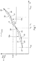
- this calibration area correction function k (9) is advantageously designed as a ratio of the effective area A W of the air spring bellows to the calibration area A W0 ; on the ordinate is the correction function k, and on the abscissa the level h is plotted.
- the correction surface correction function (9) is after Fig. 1 metrologically determined.
- the calibration level h 0 is initially set after loading the display vehicle axle with the specified load on the display vehicle axle. At this load, starting from the calibration height h 0 , the level height is then reduced once to the minimum height h min by reducing or increasing the air spring bellows pressure p L and once increased to the maximum level height h max ; for each set level height h, the air spring bellows pressure p L is measured and with the onset of this pressure p L in formula [6], the value k of the calibration surface correction function (9) is obtained Fig. 1 for this current level h. The combination of all the correction values k thus determined above the height h of the level gives the curve (9) of the calibration area correction function Fig. 1 ,
- the calibration area correction function (9) can also be approximated by a polygonal line (10a or 10b) from straight line sections (21, 22 or 23, 24, 25, 26).
- a straight line section is defined by a first interpolation point of a surface calibration value at a first actual level and a second interpolation point of a surface calibration value at a second actual level, and at least one straight line section is provided for the traverse.
- two straight line sections (21, 22) are provided, wherein for the first interpolation point (27) of the area calibration value for the first straight line section (21) the minimum level height h min and for the second interpolation point (28) of the area calibration value (numerical value "1 ") the calibration height h 0 is selected. Similarly, for the first interpolation point (28) of the surface calibration value of the second straight line section (22), the calibration height h 0 and for the second interpolation point of the surface calibration value, the maximum level height h max is selected.
- the simplified polygon (10a) with the two straight sections (21, 22) by measuring the air bag pressure at only two other level heights, namely at the minimum level height h min and at the maximum level height h max determinable. Because the minimum and maximum level heights represent limit positions and possibly are not exactly adjusted, a level in the range of the minimum and maximum level height h min and h max can be set in its place. It should be noted that for the minimum and maximum level height limit positions h min and h max nor the fundamental force-pressure relationship according to formula [1] applies and that the values for h min and h max as electronic provide stored parameters. At the lower and upper stops, the relationship according to formula [1] no longer applies and therefore the values h min and h max to the corresponding mechanical stops have a required safety clearance resulting from the construction.
- the two further interpolation points (30 and 31) are provided whose current height levels z. B. approximately in the middle of the areas between the minimum level height h min and the calibration height h 0 or between the calibration height h 0 and the maximum level height h max are.
- the traverse is therefore formed from the four straight sections (23, 24, 25, 26) and provides a better approximation compared to the traverse (10a).
- the accuracy is improved by introducing only two further points with the total of five interpolation points, the traverse (10b) approximates to a correction surface correction function (9) with its comparatively complex level influence with very good accuracy.
- Fig. 1 may be a numerical value of a corrected calibration value k-space (h) for at least a current actual level h be stored 1 1 as the pre-calculated value k at The presentation of this actual level for determining the axle load weight according to equation [4] is available: h 1 k 1
- This actual level can z. B. represent another normal driving level. If this further driving level z. B. the level height h 1 accordingly Fig. 1 As already indicated, the area calibration value k 1 corresponding to this current actual level can be stored directly as a numerical value "1.13".
- the table is advantageously supplemented by the calibration height h 0 with the associated surface calibration value, the numerical value "1", because then h 0 , h 1 , h 2 , h 3 for all level heights to be approached and h 4 the associated area calibration values 1, k 1 , k 2 , k 3 and k 4 are stored.
Landscapes
- Engineering & Computer Science (AREA)
- Mechanical Engineering (AREA)
- Physics & Mathematics (AREA)
- General Physics & Mathematics (AREA)
- Vehicle Body Suspensions (AREA)
- Instrument Panels (AREA)
Claims (9)
- Dispositif pour l'indication de la charge à l'essieu pour un véhicule avec une superstructure de véhicule suspendue, présentant une suspension pneumatique et au moins un essieu de véhicule avec au moins un soufflet de suspension pneumatique (3a, 3b), qui soutient la superstructure de véhicule au-dessus de l'essieu de véhicule, et un système de régulation de niveau, par lequel un niveau de consigne, à savoir une distance prédéterminée entre au moins l'essieu de véhicule et la superstructure de véhicule est respecté en tant que niveau réel, dans lequel le dispositif indique la charge pondérale agissant sur ledit au moins un essieu de véhicule choisi, et dans lequel le dispositif est conçu pour:- déterminer la charge d'essieu décrite comme la force pondérale de charge d'essieu par la pression (pL) dans les soufflets de suspension pneumatique (3a, 3b) associés à l'essieu de véhicule indiqué et par la surface utile (AW) des soufflets de suspension pneumatique (3a, 3b) associés à l'essieu de véhicule indiqué, et- prévoir une face de calibrage (AW0) pour la face utile (AW) des soufflets de suspension pneumatique (3a, 3b) associés à l'axe de véhicule indiqué, dans lequel la face de calibrage (AW0) est déterminée comme étant la face utile des soufflets de suspension pneumatique (3a, 3b) associés à l'essieu de véhicule indiqué pour un niveau de calibrage (h0) comme niveau réel,caractérisé en ce que
la face de calibrage (AW0) est corrigée par une fonction (k), qui décrit la relation de dépendance entre la face utile (AW) des soufflets de suspension pneumatique (3a, 3b) associés à l'essieu de véhicule indiqué et le niveau réel actuel (h) de la superstructure de véhicule, et pour la correction de la face de calibrage (AW0) on introduit le niveau réel actuel (h) dans une fonction de correction de face de calibrage. - Dispositif indicateur de la charge à l'essieu
selon la revendication 1, caractérisé en ce que l'on définit un niveau de marche normal comme niveau de calibrage (h0). - Dispositif indicateur de la charge à l'essieu
selon la revendication 1, caractérisé en ce que l'on définit le niveau réel le plus petit (hmin) comme niveau de calibrage. - Dispositif indicateur de la charge à l'essieu
selon la revendication 1, caractérisé en ce qu'une valeur de calibrage de face (k1) prévue pour la correction pour au moins un niveau réel actuel (h1) est stockée en tant que valeur pré-calculée et est disponible en cas de prescription de ce niveau réel pour la détermination de la force pondérale de charge d'essieu. - Dispositif indicateur de la charge à l'essieu
selon la revendication 4, caractérisé en ce qu'une valeur de calibrage de face (k2) prévue pour la correction pour un autre niveau de marche normal (h2) est stockée en tant que valeur pré-calculée. - Dispositif indicateur de la charge à l'essieu
selon la revendication 4, caractérisé en ce qu'un tableau est formé et stocké à partir de plus d'une valeur de calibrage de face prévue pour la correction et pré-calculée (k1, k2, k3, k4) et des niveaux réels actuels correspondants (h1, h2, h3, h4). - Dispositif indicateur de la charge à l'essieu
selon la revendication 1, caractérisé en ce que la fonction de correction de face de calibrage (k, 9) est déterminée par le rapport entre la face utile (AW) des soufflets de suspension pneumatique au niveau réel actuel (h) et la face de calibrage (AW0) au niveau de calibrage (h0). - Dispositif indicateur de la charge à l'essieu
selon la revendication 7, caractérisé en ce que la fonction de correction de face de calibrage (k) est construite sous la forme d'une ligne polygonale (10a, 10b) formée de segments de droite, dans lequel un segment de droite (21) est défini par un premier point d'appui (27) d'une valeur de calibrage de face à un premier niveau réel (hmin) et un deuxième point d'appui (28) d'une valeur de calibrage de face à un deuxième niveau réel (h0), qui limitent le segment de droite (21), et il est prévu dans la ligne polygonale au moins un segment de droite (21). - Dispositif indicateur de la charge à l'essieu
selon la revendication 8, caractérisé en ce qu'il est prévu pour la ligne polygonale (10a) deux segments de droite, un premier (21) et un deuxième (22) segments de droite, dans lequel pour le premier segment de droite (21) un niveau réel dans la région du plus petit niveau réel (hmin) est défini pour le premier point d'appui (27) et le niveau de calibrage (h0) est défini pour le deuxième point d'appui (28), et dans lequel pour le deuxième segment de droite (22) le niveau de calibrage (h0) est défini pour le premier point d'appui (28) et un niveau réel dans la région du plus grand niveau réel (hmax) est défini pour le deuxième point d'appui (29).
Applications Claiming Priority (2)
| Application Number | Priority Date | Filing Date | Title |
|---|---|---|---|
| DE102004010559 | 2004-03-04 | ||
| DE200410010559 DE102004010559A1 (de) | 2004-03-04 | 2004-03-04 | Achslastanzeigevorrichtung |
Publications (3)
| Publication Number | Publication Date |
|---|---|
| EP1571429A2 EP1571429A2 (fr) | 2005-09-07 |
| EP1571429A3 EP1571429A3 (fr) | 2009-09-23 |
| EP1571429B1 true EP1571429B1 (fr) | 2017-03-15 |
Family
ID=34745387
Family Applications (1)
| Application Number | Title | Priority Date | Filing Date |
|---|---|---|---|
| EP04028930.8A Expired - Lifetime EP1571429B1 (fr) | 2004-03-04 | 2004-12-07 | Dispositif indicateur de la charge à l'essieu. |
Country Status (3)
| Country | Link |
|---|---|
| EP (1) | EP1571429B1 (fr) |
| JP (1) | JP4957940B2 (fr) |
| DE (1) | DE102004010559A1 (fr) |
Cited By (1)
| Publication number | Priority date | Publication date | Assignee | Title |
|---|---|---|---|---|
| DE102018132697A1 (de) | 2018-12-18 | 2020-06-18 | Wabco Gmbh | Verfahren zum Ermitteln einer Achslast und Federungssystem für ein Fahrzeug |
Families Citing this family (9)
| Publication number | Priority date | Publication date | Assignee | Title |
|---|---|---|---|---|
| DE102006054977B4 (de) * | 2006-11-22 | 2017-05-04 | Wabco Gmbh | Verfahren zur Kalibrierung der Achslastanzeige eines ECAS-Niveauregelsystems |
| JP5600567B2 (ja) * | 2010-12-01 | 2014-10-01 | Udトラックス株式会社 | 車高センサのキャリブレーション方法及びキャリブレーション装置 |
| JP6260866B2 (ja) * | 2014-04-17 | 2018-01-17 | いすゞ自動車株式会社 | 車両の重量推定装置 |
| SE540329C2 (en) | 2016-10-18 | 2018-06-26 | Scania Cv Ab | A method for load determination of a vehicle, a vehicle load sensing system, a vehicle, a computer program and a compute r program product |
| US10266028B2 (en) * | 2017-04-24 | 2019-04-23 | GM Global Technology Operations LLC | Suspension system and method of control |
| DE102019111187A1 (de) * | 2019-04-30 | 2020-11-05 | Wabco Gmbh | Verfahren zur Ermittlung einer Achslast an einem mechanisch gefederten Fahrzeug |
| JP7521323B2 (ja) * | 2020-08-19 | 2024-07-24 | 株式会社アイシン | 車両用重量推定装置、重量推定方法、およびプログラム |
| CN112248738A (zh) * | 2020-10-30 | 2021-01-22 | 东风商用车有限公司 | 一种商用车电控空气悬架载荷监控系统及方法 |
| US12589626B1 (en) * | 2024-11-01 | 2026-03-31 | Contitech Deutschland Gmbh | Air spring pressure monitoring system |
Family Cites Families (10)
| Publication number | Priority date | Publication date | Assignee | Title |
|---|---|---|---|---|
| JPS52102762A (en) * | 1976-02-24 | 1977-08-29 | Kyowa Electronic Instruments | Method of correcting load for machine for measuring weight of loaded truck |
| JPS6078804A (ja) * | 1983-10-04 | 1985-05-04 | Yamaha Motor Co Ltd | 空気ばね式車高調整装置 |
| US4651838A (en) * | 1984-10-15 | 1987-03-24 | Hamilton James M | Air spring control system and method |
| JPH0623006B2 (ja) * | 1985-05-20 | 1994-03-30 | 日野自動車工業株式会社 | トラックの荷台の高さ調整装置 |
| US4832141A (en) * | 1986-11-28 | 1989-05-23 | Accu-Weigh Systems, Inc. | Vehicle mounted load indicator system |
| JP2939322B2 (ja) * | 1990-10-26 | 1999-08-25 | トヨタ自動車株式会社 | 車両の荷重検出装置 |
| EP0666469B1 (fr) * | 1994-02-02 | 1999-03-31 | Daimler-Benz Aktiengesellschaft | Dispositif indicateur de la charge à l'essieu |
| JP3494715B2 (ja) * | 1994-10-28 | 2004-02-09 | いすゞ自動車株式会社 | 自重計校正方法および装置 |
| DE10017506C2 (de) * | 2000-04-07 | 2002-08-01 | Continental Ag | Verfahren zur Bestimmung der Radaufstandskraft eines Kraftfahrzeuges |
| DE10029332B4 (de) * | 2000-06-20 | 2007-05-24 | Continental Aktiengesellschaft | Messung des Beladungszustandes eines Kraftfahrzeuges |
-
2004
- 2004-03-04 DE DE200410010559 patent/DE102004010559A1/de not_active Withdrawn
- 2004-12-07 EP EP04028930.8A patent/EP1571429B1/fr not_active Expired - Lifetime
-
2005
- 2005-03-04 JP JP2005104066A patent/JP4957940B2/ja not_active Expired - Lifetime
Non-Patent Citations (1)
| Title |
|---|
| None * |
Cited By (2)
| Publication number | Priority date | Publication date | Assignee | Title |
|---|---|---|---|---|
| DE102018132697A1 (de) | 2018-12-18 | 2020-06-18 | Wabco Gmbh | Verfahren zum Ermitteln einer Achslast und Federungssystem für ein Fahrzeug |
| WO2020126363A1 (fr) | 2018-12-18 | 2020-06-25 | Wabco Gmbh | Procédé de détermination d'une charge d'essieu et système de suspension pour un véhicule |
Also Published As
| Publication number | Publication date |
|---|---|
| EP1571429A3 (fr) | 2009-09-23 |
| JP2005300533A (ja) | 2005-10-27 |
| JP4957940B2 (ja) | 2012-06-20 |
| EP1571429A2 (fr) | 2005-09-07 |
| DE102004010559A1 (de) | 2005-09-22 |
Similar Documents
| Publication | Publication Date | Title |
|---|---|---|
| DE19853126B4 (de) | Verfahren zur Niveauregelung und Radfahrzeug mit einem Niveauregelsystem | |
| EP3727905B1 (fr) | Procédé pour déterminer une charge de l'essieu sur un véhicule amorti de manière mécanique et/ou pneumatique ou hydraulique ainsi que véhicule | |
| EP1571014B1 (fr) | Aide au démarrage pour un véhicule | |
| DE68907523T2 (de) | Steuerungssysteme für einen Stapelwagen. | |
| EP2591928B1 (fr) | Réglage de la charge d'appui d'une remorque à essieu central | |
| DE69031794T2 (de) | Aufhängungssteuersystem | |
| DE102007015356A1 (de) | Bestimmung der Masse eines Flugzeugs | |
| EP1571429B1 (fr) | Dispositif indicateur de la charge à l'essieu. | |
| EP1844961A1 (fr) | Procédé de régulation de niveau du chassis d'un véhicule par ajustement de la masse d'air dans les ressorts pneumatiques | |
| DE102021105802B4 (de) | Verfahren und System zur Korrektur der Längsverrollung aus versetzter Last mittels aktiver Verrollungsregelung | |
| DE102018119748B4 (de) | Verfahren zum Steuern einer hydropneumatischen Federung eines Fahrzeugkrans | |
| DE2531395A1 (de) | Verfahren und vorrichtung zur anzeige einer auf der ladeflaeche eines lastwagens angeordneten last | |
| EP0779167B1 (fr) | Dispositif de réglage du niveau | |
| DE19648176B4 (de) | Verfahren zur Steuerung der Schwingungsdämpfer in einem Fahrzeug mit einer Niveauregeleinrichtung | |
| DE102019111187A1 (de) | Verfahren zur Ermittlung einer Achslast an einem mechanisch gefederten Fahrzeug | |
| DE102010032046B4 (de) | Verfahren zur Niveauregulierung eines luftgefederten Kraftfahrzeugs und Vorrichtung hierfür | |
| EP4422891A1 (fr) | Procédé de détermination de la charge de roue ou de la charge d'essieu d'un véhicule à ressort pneumatique | |
| DE10225940B4 (de) | Verfahren zur Regelung einer Niveauregelanlage und Niveauregelanlage | |
| EP2390121B1 (fr) | Remorque de véhicule utilitaire et dispositif de commande pour agencement de ressort pneumatique | |
| EP4054869A1 (fr) | Système de commande de suspension pneumatique et suspension pneumatique ainsi que véhicule équipé de celle-ci ou de ceux-ci et procédé associé | |
| EP3795959A1 (fr) | Procédé de calibrage des capteurs de charge sur essieu ou sur roue | |
| DE102019212224A1 (de) | Anordnung und Verfahren zur automatischen Fahrwerksregelung | |
| DE102010037700A1 (de) | Anhänger | |
| WO2005105486A1 (fr) | Procede de reglage de niveau d'un vehicule | |
| DE102023106891A1 (de) | Elektronische Steuereinheit einer Niveauregulierungseinrichtung eines Fahrzeugs so-wie Verfahren zur Achslastermittlung mit einer solchen Steuereinheit |
Legal Events
| Date | Code | Title | Description |
|---|---|---|---|
| PUAI | Public reference made under article 153(3) epc to a published international application that has entered the european phase |
Free format text: ORIGINAL CODE: 0009012 |
|
| AK | Designated contracting states |
Kind code of ref document: A2 Designated state(s): AT BE BG CH CY CZ DE DK EE ES FI FR GB GR HU IE IS IT LI LT LU MC NL PL PT RO SE SI SK TR |
|
| AX | Request for extension of the european patent |
Extension state: AL BA HR LV MK YU |
|
| RAP1 | Party data changed (applicant data changed or rights of an application transferred) |
Owner name: WABCO GMBH |
|
| PUAL | Search report despatched |
Free format text: ORIGINAL CODE: 0009013 |
|
| AK | Designated contracting states |
Kind code of ref document: A3 Designated state(s): AT BE BG CH CY CZ DE DK EE ES FI FR GB GR HU IE IS IT LI LT LU MC NL PL PT RO SE SI SK TR |
|
| AX | Request for extension of the european patent |
Extension state: AL BA HR LV MK YU |
|
| RIC1 | Information provided on ipc code assigned before grant |
Ipc: G01G 19/10 20060101AFI20090819BHEP Ipc: B60G 17/015 20060101ALI20090819BHEP Ipc: G01G 23/01 20060101ALI20090819BHEP Ipc: B60G 17/052 20060101ALI20090819BHEP |
|
| 17P | Request for examination filed |
Effective date: 20100323 |
|
| AKX | Designation fees paid |
Designated state(s): DE FR IT SE |
|
| 17Q | First examination report despatched |
Effective date: 20100429 |
|
| GRAP | Despatch of communication of intention to grant a patent |
Free format text: ORIGINAL CODE: EPIDOSNIGR1 |
|
| GRAJ | Information related to disapproval of communication of intention to grant by the applicant or resumption of examination proceedings by the epo deleted |
Free format text: ORIGINAL CODE: EPIDOSDIGR1 |
|
| STAA | Information on the status of an ep patent application or granted ep patent |
Free format text: STATUS: EXAMINATION IS IN PROGRESS |
|
| INTG | Intention to grant announced |
Effective date: 20161025 |
|
| GRAP | Despatch of communication of intention to grant a patent |
Free format text: ORIGINAL CODE: EPIDOSNIGR1 |
|
| STAA | Information on the status of an ep patent application or granted ep patent |
Free format text: STATUS: GRANT OF PATENT IS INTENDED |
|
| INTC | Intention to grant announced (deleted) | ||
| INTG | Intention to grant announced |
Effective date: 20161206 |
|
| GRAS | Grant fee paid |
Free format text: ORIGINAL CODE: EPIDOSNIGR3 |
|
| GRAA | (expected) grant |
Free format text: ORIGINAL CODE: 0009210 |
|
| STAA | Information on the status of an ep patent application or granted ep patent |
Free format text: STATUS: THE PATENT HAS BEEN GRANTED |
|
| AK | Designated contracting states |
Kind code of ref document: B1 Designated state(s): DE FR IT SE |
|
| REG | Reference to a national code |
Ref country code: DE Ref legal event code: R081 Ref document number: 502004015478 Country of ref document: DE Owner name: ZF CV SYSTEMS EUROPE BV, BE Free format text: FORMER OWNER: WABCO GMBH & CO.OHG, 30453 HANNOVER, DE Ref country code: DE Ref legal event code: R081 Ref document number: 502004015478 Country of ref document: DE Owner name: ZF CV SYSTEMS HANNOVER GMBH, DE Free format text: FORMER OWNER: WABCO GMBH & CO.OHG, 30453 HANNOVER, DE |
|
| REG | Reference to a national code |
Ref country code: DE Ref legal event code: R096 Ref document number: 502004015478 Country of ref document: DE |
|
| REG | Reference to a national code |
Ref country code: SE Ref legal event code: TRGR |
|
| REG | Reference to a national code |
Ref country code: DE Ref legal event code: R097 Ref document number: 502004015478 Country of ref document: DE |
|
| REG | Reference to a national code |
Ref country code: FR Ref legal event code: PLFP Year of fee payment: 14 |
|
| PLBE | No opposition filed within time limit |
Free format text: ORIGINAL CODE: 0009261 |
|
| STAA | Information on the status of an ep patent application or granted ep patent |
Free format text: STATUS: NO OPPOSITION FILED WITHIN TIME LIMIT |
|
| 26N | No opposition filed |
Effective date: 20171218 |
|
| REG | Reference to a national code |
Ref country code: DE Ref legal event code: R081 Ref document number: 502004015478 Country of ref document: DE Owner name: ZF CV SYSTEMS EUROPE BV, BE Free format text: FORMER OWNER: WABCO GMBH, 30453 HANNOVER, DE Ref country code: DE Ref legal event code: R081 Ref document number: 502004015478 Country of ref document: DE Owner name: ZF CV SYSTEMS HANNOVER GMBH, DE Free format text: FORMER OWNER: WABCO GMBH, 30453 HANNOVER, DE |
|
| REG | Reference to a national code |
Ref country code: DE Ref legal event code: R081 Ref document number: 502004015478 Country of ref document: DE Owner name: ZF CV SYSTEMS EUROPE BV, BE Free format text: FORMER OWNER: ZF CV SYSTEMS HANNOVER GMBH, 30453 HANNOVER, DE |
|
| P01 | Opt-out of the competence of the unified patent court (upc) registered |
Effective date: 20230528 |
|
| PGFP | Annual fee paid to national office [announced via postgrant information from national office to epo] |
Ref country code: FR Payment date: 20230929 Year of fee payment: 20 |
|
| PGFP | Annual fee paid to national office [announced via postgrant information from national office to epo] |
Ref country code: SE Payment date: 20231002 Year of fee payment: 20 Ref country code: IT Payment date: 20231110 Year of fee payment: 20 Ref country code: DE Payment date: 20231010 Year of fee payment: 20 |
|
| REG | Reference to a national code |
Ref country code: DE Ref legal event code: R071 Ref document number: 502004015478 Country of ref document: DE |
|
| REG | Reference to a national code |
Ref country code: SE Ref legal event code: EUG |