EP1571468A1 - Verfahren zur Herstellung eines Spiegels, Spiegel, Beleuctungseinheit und Bildwerfer - Google Patents
Verfahren zur Herstellung eines Spiegels, Spiegel, Beleuctungseinheit und Bildwerfer Download PDFInfo
- Publication number
- EP1571468A1 EP1571468A1 EP05004029A EP05004029A EP1571468A1 EP 1571468 A1 EP1571468 A1 EP 1571468A1 EP 05004029 A EP05004029 A EP 05004029A EP 05004029 A EP05004029 A EP 05004029A EP 1571468 A1 EP1571468 A1 EP 1571468A1
- Authority
- EP
- European Patent Office
- Prior art keywords
- reflecting mirror
- light
- reflecting
- quartz glass
- illumination device
- Prior art date
- Legal status (The legal status is an assumption and is not a legal conclusion. Google has not performed a legal analysis and makes no representation as to the accuracy of the status listed.)
- Granted
Links
- 238000005286 illumination Methods 0.000 title claims abstract description 56
- 238000004519 manufacturing process Methods 0.000 title claims abstract description 31
- 238000000034 method Methods 0.000 title claims abstract description 29
- VYPSYNLAJGMNEJ-UHFFFAOYSA-N Silicium dioxide Chemical compound O=[Si]=O VYPSYNLAJGMNEJ-UHFFFAOYSA-N 0.000 claims abstract description 30
- 238000005520 cutting process Methods 0.000 claims abstract description 13
- 238000000465 moulding Methods 0.000 claims abstract description 10
- 238000001704 evaporation Methods 0.000 claims abstract description 8
- 238000010438 heat treatment Methods 0.000 claims abstract description 4
- 230000008020 evaporation Effects 0.000 claims abstract 2
- 230000003287 optical effect Effects 0.000 claims description 32
- 230000004907 flux Effects 0.000 claims description 19
- 239000004973 liquid crystal related substance Substances 0.000 description 20
- 238000010586 diagram Methods 0.000 description 10
- 238000006073 displacement reaction Methods 0.000 description 9
- 239000007789 gas Substances 0.000 description 5
- 230000010287 polarization Effects 0.000 description 5
- 238000000926 separation method Methods 0.000 description 5
- 230000000694 effects Effects 0.000 description 4
- 238000007789 sealing Methods 0.000 description 4
- 230000002194 synthesizing effect Effects 0.000 description 4
- 238000006243 chemical reaction Methods 0.000 description 3
- 239000003086 colorant Substances 0.000 description 3
- 239000010453 quartz Substances 0.000 description 3
- 239000000853 adhesive Substances 0.000 description 2
- 230000001070 adhesive effect Effects 0.000 description 2
- 239000004568 cement Substances 0.000 description 2
- 230000007423 decrease Effects 0.000 description 2
- 230000003247 decreasing effect Effects 0.000 description 2
- 239000011888 foil Substances 0.000 description 2
- 239000000463 material Substances 0.000 description 2
- QSHDDOUJBYECFT-UHFFFAOYSA-N mercury Chemical compound [Hg] QSHDDOUJBYECFT-UHFFFAOYSA-N 0.000 description 2
- 229910052753 mercury Inorganic materials 0.000 description 2
- 229910052751 metal Inorganic materials 0.000 description 2
- 239000002184 metal Substances 0.000 description 2
- 238000012986 modification Methods 0.000 description 2
- 230000004048 modification Effects 0.000 description 2
- ZOKXTWBITQBERF-UHFFFAOYSA-N Molybdenum Chemical compound [Mo] ZOKXTWBITQBERF-UHFFFAOYSA-N 0.000 description 1
- 230000004308 accommodation Effects 0.000 description 1
- PNEYBMLMFCGWSK-UHFFFAOYSA-N aluminium oxide Inorganic materials [O-2].[O-2].[O-2].[Al+3].[Al+3] PNEYBMLMFCGWSK-UHFFFAOYSA-N 0.000 description 1
- 238000000149 argon plasma sintering Methods 0.000 description 1
- 238000003491 array Methods 0.000 description 1
- 230000015572 biosynthetic process Effects 0.000 description 1
- 238000000071 blow moulding Methods 0.000 description 1
- WUKWITHWXAAZEY-UHFFFAOYSA-L calcium difluoride Chemical compound [F-].[F-].[Ca+2] WUKWITHWXAAZEY-UHFFFAOYSA-L 0.000 description 1
- 238000000151 deposition Methods 0.000 description 1
- 238000005516 engineering process Methods 0.000 description 1
- 239000010436 fluorite Substances 0.000 description 1
- 239000003292 glue Substances 0.000 description 1
- 229910052736 halogen Inorganic materials 0.000 description 1
- 150000002367 halogens Chemical class 0.000 description 1
- 239000011261 inert gas Substances 0.000 description 1
- 238000009434 installation Methods 0.000 description 1
- WABPQHHGFIMREM-UHFFFAOYSA-N lead(0) Chemical compound [Pb] WABPQHHGFIMREM-UHFFFAOYSA-N 0.000 description 1
- 229910001507 metal halide Inorganic materials 0.000 description 1
- 150000005309 metal halides Chemical class 0.000 description 1
- 229910052750 molybdenum Inorganic materials 0.000 description 1
- 239000011733 molybdenum Substances 0.000 description 1
- 238000005086 pumping Methods 0.000 description 1
- 229910052594 sapphire Inorganic materials 0.000 description 1
- 239000010980 sapphire Substances 0.000 description 1
- 238000004544 sputter deposition Methods 0.000 description 1
- 239000007858 starting material Substances 0.000 description 1
- WFKWXMTUELFFGS-UHFFFAOYSA-N tungsten Chemical compound [W] WFKWXMTUELFFGS-UHFFFAOYSA-N 0.000 description 1
- 229910052721 tungsten Inorganic materials 0.000 description 1
- 239000010937 tungsten Substances 0.000 description 1
- 238000007740 vapor deposition Methods 0.000 description 1
- 229910052724 xenon Inorganic materials 0.000 description 1
- FHNFHKCVQCLJFQ-UHFFFAOYSA-N xenon atom Chemical compound [Xe] FHNFHKCVQCLJFQ-UHFFFAOYSA-N 0.000 description 1
Images



Classifications
-
- H—ELECTRICITY
- H01—ELECTRIC ELEMENTS
- H01J—ELECTRIC DISCHARGE TUBES OR DISCHARGE LAMPS
- H01J9/00—Apparatus or processes specially adapted for the manufacture, installation, removal, maintenance of electric discharge tubes, discharge lamps, or parts thereof; Recovery of material from discharge tubes or lamps
- H01J9/20—Manufacture of screens on or from which an image or pattern is formed, picked up, converted or stored; Applying coatings to the vessel
-
- F—MECHANICAL ENGINEERING; LIGHTING; HEATING; WEAPONS; BLASTING
- F24—HEATING; RANGES; VENTILATING
- F24F—AIR-CONDITIONING; AIR-HUMIDIFICATION; VENTILATION; USE OF AIR CURRENTS FOR SCREENING
- F24F6/00—Air-humidification, e.g. cooling by humidification
- F24F6/12—Air-humidification, e.g. cooling by humidification by forming water dispersions in the air
- F24F6/14—Air-humidification, e.g. cooling by humidification by forming water dispersions in the air using nozzles
-
- C—CHEMISTRY; METALLURGY
- C03—GLASS; MINERAL OR SLAG WOOL
- C03B—MANUFACTURE, SHAPING, OR SUPPLEMENTARY PROCESSES
- C03B23/00—Re-forming shaped glass
- C03B23/04—Re-forming tubes or rods
- C03B23/049—Re-forming tubes or rods by pressing
- C03B23/0493—Re-forming tubes or rods by pressing in a longitudinal direction, e.g. for upsetting or extrusion
-
- C—CHEMISTRY; METALLURGY
- C03—GLASS; MINERAL OR SLAG WOOL
- C03B—MANUFACTURE, SHAPING, OR SUPPLEMENTARY PROCESSES
- C03B23/00—Re-forming shaped glass
- C03B23/04—Re-forming tubes or rods
- C03B23/07—Re-forming tubes or rods by blowing, e.g. for making electric bulbs
-
- C—CHEMISTRY; METALLURGY
- C03—GLASS; MINERAL OR SLAG WOOL
- C03B—MANUFACTURE, SHAPING, OR SUPPLEMENTARY PROCESSES
- C03B33/00—Severing cooled glass
- C03B33/06—Cutting or splitting glass tubes, rods, or hollow products
-
- C—CHEMISTRY; METALLURGY
- C03—GLASS; MINERAL OR SLAG WOOL
- C03C—CHEMICAL COMPOSITION OF GLASSES, GLAZES OR VITREOUS ENAMELS; SURFACE TREATMENT OF GLASS; SURFACE TREATMENT OF FIBRES OR FILAMENTS MADE FROM GLASS, MINERALS OR SLAGS; JOINING GLASS TO GLASS OR OTHER MATERIALS
- C03C17/00—Surface treatment of glass, not in the form of fibres or filaments, by coating
- C03C17/001—General methods for coating; Devices therefor
-
- C—CHEMISTRY; METALLURGY
- C03—GLASS; MINERAL OR SLAG WOOL
- C03C—CHEMICAL COMPOSITION OF GLASSES, GLAZES OR VITREOUS ENAMELS; SURFACE TREATMENT OF GLASS; SURFACE TREATMENT OF FIBRES OR FILAMENTS MADE FROM GLASS, MINERALS OR SLAGS; JOINING GLASS TO GLASS OR OTHER MATERIALS
- C03C17/00—Surface treatment of glass, not in the form of fibres or filaments, by coating
- C03C17/06—Surface treatment of glass, not in the form of fibres or filaments, by coating with metals
- C03C17/09—Surface treatment of glass, not in the form of fibres or filaments, by coating with metals by deposition from the vapour phase
-
- C—CHEMISTRY; METALLURGY
- C03—GLASS; MINERAL OR SLAG WOOL
- C03C—CHEMICAL COMPOSITION OF GLASSES, GLAZES OR VITREOUS ENAMELS; SURFACE TREATMENT OF GLASS; SURFACE TREATMENT OF FIBRES OR FILAMENTS MADE FROM GLASS, MINERALS OR SLAGS; JOINING GLASS TO GLASS OR OTHER MATERIALS
- C03C17/00—Surface treatment of glass, not in the form of fibres or filaments, by coating
- C03C17/34—Surface treatment of glass, not in the form of fibres or filaments, by coating with at least two coatings having different compositions
- C03C17/36—Surface treatment of glass, not in the form of fibres or filaments, by coating with at least two coatings having different compositions at least one coating being a metal
-
- C—CHEMISTRY; METALLURGY
- C03—GLASS; MINERAL OR SLAG WOOL
- C03C—CHEMICAL COMPOSITION OF GLASSES, GLAZES OR VITREOUS ENAMELS; SURFACE TREATMENT OF GLASS; SURFACE TREATMENT OF FIBRES OR FILAMENTS MADE FROM GLASS, MINERALS OR SLAGS; JOINING GLASS TO GLASS OR OTHER MATERIALS
- C03C17/00—Surface treatment of glass, not in the form of fibres or filaments, by coating
- C03C17/34—Surface treatment of glass, not in the form of fibres or filaments, by coating with at least two coatings having different compositions
- C03C17/36—Surface treatment of glass, not in the form of fibres or filaments, by coating with at least two coatings having different compositions at least one coating being a metal
- C03C17/3602—Surface treatment of glass, not in the form of fibres or filaments, by coating with at least two coatings having different compositions at least one coating being a metal the metal being present as a layer
- C03C17/3657—Surface treatment of glass, not in the form of fibres or filaments, by coating with at least two coatings having different compositions at least one coating being a metal the metal being present as a layer the multilayer coating having optical properties
- C03C17/3663—Surface treatment of glass, not in the form of fibres or filaments, by coating with at least two coatings having different compositions at least one coating being a metal the metal being present as a layer the multilayer coating having optical properties specially adapted for use as mirrors
-
- F—MECHANICAL ENGINEERING; LIGHTING; HEATING; WEAPONS; BLASTING
- F24—HEATING; RANGES; VENTILATING
- F24F—AIR-CONDITIONING; AIR-HUMIDIFICATION; VENTILATION; USE OF AIR CURRENTS FOR SCREENING
- F24F6/00—Air-humidification, e.g. cooling by humidification
- F24F6/12—Air-humidification, e.g. cooling by humidification by forming water dispersions in the air
- F24F6/16—Air-humidification, e.g. cooling by humidification by forming water dispersions in the air using rotating elements
-
- G—PHYSICS
- G02—OPTICS
- G02B—OPTICAL ELEMENTS, SYSTEMS OR APPARATUS
- G02B5/00—Optical elements other than lenses
- G02B5/08—Mirrors
- G02B5/0808—Mirrors having a single reflecting layer
-
- G—PHYSICS
- G02—OPTICS
- G02B—OPTICAL ELEMENTS, SYSTEMS OR APPARATUS
- G02B5/00—Optical elements other than lenses
- G02B5/08—Mirrors
- G02B5/10—Mirrors with curved faces
-
- G—PHYSICS
- G03—PHOTOGRAPHY; CINEMATOGRAPHY; ANALOGOUS TECHNIQUES USING WAVES OTHER THAN OPTICAL WAVES; ELECTROGRAPHY; HOLOGRAPHY
- G03B—APPARATUS OR ARRANGEMENTS FOR TAKING PHOTOGRAPHS OR FOR PROJECTING OR VIEWING THEM; APPARATUS OR ARRANGEMENTS EMPLOYING ANALOGOUS TECHNIQUES USING WAVES OTHER THAN OPTICAL WAVES; ACCESSORIES THEREFOR
- G03B21/00—Projectors or projection-type viewers; Accessories therefor
- G03B21/14—Details
- G03B21/20—Lamp housings
- G03B21/2006—Lamp housings characterised by the light source
- G03B21/2026—Gas discharge type light sources, e.g. arcs
-
- G—PHYSICS
- G03—PHOTOGRAPHY; CINEMATOGRAPHY; ANALOGOUS TECHNIQUES USING WAVES OTHER THAN OPTICAL WAVES; ELECTROGRAPHY; HOLOGRAPHY
- G03B—APPARATUS OR ARRANGEMENTS FOR TAKING PHOTOGRAPHS OR FOR PROJECTING OR VIEWING THEM; APPARATUS OR ARRANGEMENTS EMPLOYING ANALOGOUS TECHNIQUES USING WAVES OTHER THAN OPTICAL WAVES; ACCESSORIES THEREFOR
- G03B21/00—Projectors or projection-type viewers; Accessories therefor
- G03B21/14—Details
- G03B21/20—Lamp housings
- G03B21/2066—Reflectors in illumination beam
-
- H—ELECTRICITY
- H01—ELECTRIC ELEMENTS
- H01J—ELECTRIC DISCHARGE TUBES OR DISCHARGE LAMPS
- H01J61/00—Gas-discharge or vapour-discharge lamps
- H01J61/02—Details
- H01J61/025—Associated optical elements
-
- H—ELECTRICITY
- H01—ELECTRIC ELEMENTS
- H01J—ELECTRIC DISCHARGE TUBES OR DISCHARGE LAMPS
- H01J61/00—Gas-discharge or vapour-discharge lamps
- H01J61/02—Details
- H01J61/30—Vessels; Containers
- H01J61/35—Vessels; Containers provided with coatings on the walls thereof; Selection of materials for the coatings
-
- H—ELECTRICITY
- H01—ELECTRIC ELEMENTS
- H01J—ELECTRIC DISCHARGE TUBES OR DISCHARGE LAMPS
- H01J9/00—Apparatus or processes specially adapted for the manufacture, installation, removal, maintenance of electric discharge tubes, discharge lamps, or parts thereof; Recovery of material from discharge tubes or lamps
- H01J9/24—Manufacture or joining of vessels, leading-in conductors or bases
- H01J9/245—Manufacture or joining of vessels, leading-in conductors or bases specially adapted for gas discharge tubes or lamps
- H01J9/247—Manufacture or joining of vessels, leading-in conductors or bases specially adapted for gas discharge tubes or lamps specially adapted for gas-discharge lamps
-
- H—ELECTRICITY
- H04—ELECTRIC COMMUNICATION TECHNIQUE
- H04N—PICTORIAL COMMUNICATION, e.g. TELEVISION
- H04N9/00—Details of colour television systems
- H04N9/12—Picture reproducers
- H04N9/31—Projection devices for colour picture display, e.g. using electronic spatial light modulators [ESLM]
- H04N9/3141—Constructional details thereof
- H04N9/315—Modulator illumination systems
-
- F—MECHANICAL ENGINEERING; LIGHTING; HEATING; WEAPONS; BLASTING
- F21—LIGHTING
- F21V—FUNCTIONAL FEATURES OR DETAILS OF LIGHTING DEVICES OR SYSTEMS THEREOF; STRUCTURAL COMBINATIONS OF LIGHTING DEVICES WITH OTHER ARTICLES, NOT OTHERWISE PROVIDED FOR
- F21V7/00—Reflectors for light sources
- F21V7/0025—Combination of two or more reflectors for a single light source
-
- F—MECHANICAL ENGINEERING; LIGHTING; HEATING; WEAPONS; BLASTING
- F21—LIGHTING
- F21V—FUNCTIONAL FEATURES OR DETAILS OF LIGHTING DEVICES OR SYSTEMS THEREOF; STRUCTURAL COMBINATIONS OF LIGHTING DEVICES WITH OTHER ARTICLES, NOT OTHERWISE PROVIDED FOR
- F21V7/00—Reflectors for light sources
- F21V7/10—Construction
Definitions
- the present invention relates to a method for the manufacture of an auxiliary reflecting mirror for installation in an illumination device, the auxiliary reflecting mirror manufactured by such a manufacturing method, an illumination device equipped with such an auxiliary reflecting mirror, and a projector equipped with such an illumination device.
- a technology has been known by which in an illumination device equipped with a light-emitting tube and a main reflecting mirror for directing the light emitted from the light-emitting tube in the prescribed direction, an auxiliary reflecting mirror composed of quartz or the like was provided in a position facing the main reflecting mirror on the other side of the light-emitting tube and it was possible to utilize effectively the light that was emitted from the light-emitting tube, but became a stray light and was not supplied for use (see, for example, Patent Reference 1).
- Patent Reference 1 JP-A-H8-31382 (second page, FIG. 1).
- the auxiliary reflecting mirror was provided with the object of increasing the light effective efficiency, a high accuracy was required for the reflecting surface thereof.
- the present invention was created to resolve this problem and it is an object thereof to provide a method for the manufacture of a reflecting mirror, which makes it possible to form the reflecting surface with good accuracy and manufacture a reflecting mirror with a high light utilization efficiency, the reflecting mirror manufactured by such a method, an illumination device equipped with such a reflecting mirror, and a projector equipped with such an illumination device.
- the method for the manufacture of a reflecting mirror in accordance with the present invention is a method for the manufacture of a reflecting mirror of an illumination device comprising a light-emitting tube and the reflecting mirror for reflecting a light from the light-emitting tube, this method comprising a bulging step of heating the central portion of a quartz glass tube and compressing the central portion by pushing the two end portions of the quartz glass tube so that the wall thickness of the central portion thickens, an expanding step of accommodating the quartz glass tube after the bulging step in a molding mold having an inner surface formed to the reflecting surface shape which is to be formed in a reflecting mirror, and forming an expanded portion by expanding the central portion, of which the wall thickness was thickened, by introducing a gas from the two ends of the quartz glass tube, a cutting step of cutting the quartz glass tube in at least the central portion of the expanded portion, and an evaporating step of evaporating a reflecting film on the outer surface of the expanded portion and forming a reflecting surface.
- the reflecting surface can be formed with good
- both end portions of the cylindrical portions extending outwardly from the two ends of the expanded portion are cut in addition to cutting in the vicinity of the central portion of the expanded portion of the quartz glass tube, and cylindrical mounting support portions provided for fixing to the light-emitting tube are formed. Because the mounting support portions are thus formed, an auxiliary reflecting mirror with good mounting ability on the light-emitting tube can be manufactured.
- the reflecting mirror in accordance with the present invention is manufactured by the above-described method for the manufacture of a reflecting mirror.
- the reflecting mirror thus manufactured has a high light utilization efficiency and good mounting ability on the light-emitting tube.
- the illumination device in accordance with the present invention comprises a light-emitting tube and a reflecting mirror for reflecting the light from the light-emitting tube toward an illumination region, wherein the reflecting mirror is manufactured by the above-described method for the manufacture of a reflecting mirror. Because the reflecting mirror manufactured by the above-described manufacturing method is provided, an illumination device with a high light utilization efficiency can be obtained.
- the illumination device in accordance with the present invention comprises a light-emitting tube, a main reflecting mirror for reflecting the light from the light-emitting tube toward an illumination region, and an auxiliary reflecting mirror for reflecting the light from the light-emitting tube toward the main reflecting mirror, wherein the auxiliary reflecting mirror is manufactured by the above-described method for the manufacture of a reflecting mirror. Because the auxiliary reflecting mirror manufactured by the above-described manufacturing method is provided, an illumination device with a high light utilization efficiency can be obtained.
- the projector in accordance with the present invention comprises the above-described illumination device, a light modulation device for modulating the luminous flux emitted from the illumination device according to an image information, and a projection optical system for projecting the luminous flux modulated by the light modulation device. Because the above-described illumination device is provided, a projector with increased luminosity can be obtained.
- FIG. 1(a) illustrates an illumination device comprising an auxiliary reflecting mirror manufactured by the method for the manufacture of a reflecting mirror in accordance with the present invention.
- This illumination device 100 comprises a light-emitting tube 10, a main reflecting mirror 20 for reflecting the light from the light-emitting tube 10 toward the illumination region, and an auxiliary reflecting mirror 30 for reflecting the light from the light-emitting tube 10 toward the main reflecting mirror 20.
- the light-emitting tube 10 is made from quartz glass or the like and is composed of a central light-emitting portion 11 having sealed inside thereof tungsten electrodes 12, 12, mercury, a rare gas, and a small amount of a halogen, and sealing portions 13, 13 on both sides of the light-emitting portion 11.
- a metal foil 14 composed of molybdenum and connected to the electrode 12 is sealed hermetically in each sealing portion 13, and each metal foil 14, 14 is provided with respective lead wire 15, 15 leading to the outside.
- the light-emitting tube 10 is not limited to a mercury lamp and may be a metal halide lamp or a xenon lamp.
- the main reflecting mirror 20 is a reflecting element disposed behind the light-emitting portion 11 and comprises a reflecting portion having a concave reflecting surface shaped as an ellipsoid of rotation and a through hole 21 for fixing the light-emitting tube 10, this through hole being located in the central portion of the reflecting portion.
- the light-emitting tube 10 is fixed with an inorganic adhesive 22 such as a cement in the through hole 21 of the main reflecting mirror 20 so that the axis of the light-emitting tube 10 and the axis of the main reflecting mirror 20 coincide with each other and that the arc image generated between a pair of electrodes 12 and the first focal point of the main reflecting mirror 20 coincide with each other.
- the auxiliary reflecting mirror 30 is a reflecting element disposed in front of the light-emitting portion 11 and is fabricated by using, for example, quartz or Neoceram, which is a material with a low thermal expansion, or transparent alumina, sapphire, quartz, fluorite, or YAG which are the materials with a high thermal conductivity.
- the auxiliary reflecting mirror 30 comprises a concave portion 31 having a reflecting surface 32 and enclosing almost half of the front side of the light-emitting portion 11 and a mounting support portion 35 extending outwardly from the central portion of the concave portion 31 and provided for fixing to the light-emitting tube 10.
- a reflecting surface 32 is formed on the outer surface 33.
- the auxiliary reflecting mirror 30 of such a configuration is inserted into the mounting support portion 35 so that the axis of the sealing portion 13 of the light-emitting tube 10 coincides with the axis of the auxiliary reflecting mirror 30, the focal point of the reflecting surface 32 is made to coincide with the arc image generated between the pair of electrodes 12, an inorganic adhesive 40 such as a cement is injected into a gap between the inner periphery of the mounting support portion 35 and the outer periphery of the sealing portion, and the auxiliary reflecting mirror is fixed to the light-emitting tube 10.
- the luminous flux emitted from the illumination device 100 will be explained in detail herein with reference to FIG. 1(b).
- a luminous flux B1 that was directed straight to the main reflecting mirror 20 is reflected by the reflecting surface of the main reflecting mirror 20 and outgoes toward the position of a second focal point F2.
- a luminous flux B2 emitted from the arc image generated between the pair of electrodes 12 of the light-emitting portion 11 in the direction opposite the main reflecting mirror 20 is reflected by the reflecting surface 32 of the auxiliary reflecting mirror 30 toward the main reflecting mirror 20, then reflected by the reflecting surface of the main reflecting mirror 20, and outgoes from the main reflecting mirror 20 so as to be converged toward the position of the second focal point F2.
- the luminous flux emitted from the light-emitting portion 11 had to be converged in the position of the second focal point F2 only with the main reflecting mirror and the aperture diameter of the reflecting surface of the main reflecting mirror had to be increased.
- providing the auxiliary reflecting mirror 30 makes it possible to reflect the luminous flux that is emitted from the light-emitting portion 11 in the direction (forward) opposite to the main reflecting mirror 20 with the auxiliary reflecting mirror 30 so that it falls on the reflecting surface of the main reflecting mirror 20.
- the illumination device 100 can be miniaturized and the inner layout of an electronic device, for example, a projector incorporating the illumination device 100 is facilitated.
- auxiliary reflecting mirror 30 decreases the light gathering spot diameter in the second focal point F2. Therefore, even if the distance between the first focal point F1 and second focal point F2 of the main reflecting mirror 20 is decreased, almost the entire light emitted from the light-emitting portion 11 can be gathered by the main reflecting mirror 20 and auxiliary reflecting mirror 30 in the second focal point and used, and the light utilization efficiency can be greatly increased.
- the auxiliary reflecting mirror 30 As described hereinabove, because the auxiliary reflecting mirror 30 is used, the luminous flux emitted from the light-emitting portion 11 in the direction (forward) opposite to the main reflecting mirror 20 is converged in the position of the second focal point F2 of the main reflecting mirror 20 similarly to the luminous flux directly falling from the light-emitting portion 11 on the reflecting surface of the main reflecting mirror 20, thereby increasing the light utilization efficiency of the illumination device 100. Therefore, the auxiliary reflecting mirror 30 having the reflecting surface 32 with a better molding accuracy makes it possible to construct the illumination device 100 in which the effect of installing the auxiliary reflecting mirror 30 can be demonstrated to even greater degree.
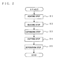
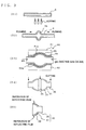
- FIG. 2 and FIG. 3 show a process flow diagram and process model diagram explaining the method for the manufacture of the auxiliary reflecting mirror of one embodiment of the present invention, and the explanation will be conducted following those diagrams.
- the central portion of, for example, quartz glass tube 6, which is a starting material is heated to the prescribed high temperature and made easily deformable (S1 in FIG. 2 and FIG. 3, referred to hereinbelow as a heating step).
- the two end portions of the quartz glass tube 6 are pushed and compressed in the central direction to cause bulging in the central portion 6a (S2 in FIG. 2 and FIG. 3, referred to herein below as a bulging step).
- the central portion 6a is compressed by pushing the two end portions of the quartz glass tube 6 so that the wall thickness of the central portion 6a thickens.
- the bulged quartz glass tube 6 (the central portion 6a having the thickened wall thickness) is accommodated in a molding mold 80 and in this state blow molding is conducted by pumping a gas (inert gas or air) from the two end portions of the quartz glass tube 6 and the bulged central portion 6a (the central portion 6a having the thickened wall thickness) is expanded and an expanded portion 6b is formed (S3 in FIG. 2 and FIG. 3, referred to hereinbelow as an expansion step).
- a gas in FIG. 2 and FIG. 3, referred to hereinbelow as an expansion step.
- the upper mold 81 and lower mold 82 of the molding mold 80 have the inner surfaces 81a, 82a formed to a shape which is ideal as a shape of the reflecting surface 32, which is to be formed in the auxiliary reflecting mirror 30, and because the central portion 6a is expanded in a state of accommodation inside the molding mold 80, the ideal reflecting surface shape is transferred onto the outer surface 33 of the expanded portion 6b.
- the gas is blown onto the inner surface 34 of the expanded portion 6b in the expansion step, this inner surface is difficult to form to the desired reflecting surface shape.
- the quartz glass tube 6 is cut in two in the vicinity of the center of the expanded portion 6b thereof and both end portions of the cylindrical portions 6c extending outwardly from the two ends of the expanded portion 6b are cut off (S4 in FIG. 2 and FIG. 3, referred to hereinbelow as a cutting step).
- a cutting step an auxiliary reflecting mirror body is formed which is composed of a concave portion 31 having an almost semispherical concave surface and a mounting support portion 35 extending outwardly from the central portion of the concave portion 31.
- a reflecting surface 32 is formed by evaporating a reflecting film by sputtering or the like on the outer surface 33 of the concave portion 31, which had, as described hereinabove, a high accuracy as the surface for forming the reflecting surface (S5 in FIG. 2 and FIG. 3, referred to herein below as an evaporating step).
- the reflecting surface 32 becomes a reflecting surface capable of reflecting with good efficiency the light from the light-emitting tube 10 toward the main reflecting mirror 20.
- the reflecting surface 32 was formed on the outer surface 33 side of the concave portion 31 onto which the ideal reflecting surface shape provided on the molding mold 80 was transferred. Therefore, the reflecting surface 32 can be formed with good accuracy and it is possible to obtain the auxiliary reflecting mirror 30 with a high light utilization efficiency, which is capable of reflecting with good efficiency the light from the light-emitting tube 10 toward the main reflecting mirror 20. As a consequence, the illumination device 100 with a high light utilization efficiency can be obtained.
- the auxiliary reflecting mirror 30 has the mounting support portion 35, mounting on the light-emitting tube 10 is facilitated as compared with the configuration comprising only the concave portion 31, without the mounting support portion 35. Further, the mounting support portion 35 is effective from the standpoint of mounting ability, but the present invention is not necessarily limited to the configuration comprising the mounting support portion 35.
- the illumination device 100 in accordance with the present invention is not limited to the above-described embodiment and can be implemented in a variety of modes, without departing from the essence thereof.
- the following modifications are also possible.
- an example was described in which the expanded portion 6b was cut in the central portion and then the reflecting surface 32 was formed by vapor depositing the reflecting film on the outer surface of the concave portion 31.
- a method for the manufacture of the auxiliary reflecting mirror 30 was explained, but the main reflecting mirror 20 also may be manufactured by a similar manufacturing method.
- FIG. 4 is an explanatory drawing illustrating the comparison of the optical paths of the reflected light in the case where the reflecting film was provided on the inner surface of the auxiliary reflecting mirror and the case where it was provided on the outer surface.
- the reference symbol 34a stands for an ideal inner surface of the auxiliary reflecting mirror 30, and the actual inner surface 34 is assumed to be inclined at an angle ⁇ with respect to this ideal inner surface 34a.
- the reference symbol 50 stands for a light source under an assumption that the center of the light-emitting portion 11 is a point light source
- 50' stands for a reflected light source in the case where the reflection was on the ideal inner surface 34a
- 51 stands for a reflected light source in the case where the reflection was on the actual inner surface 34
- 52 stands for a reflected light source in the case where the reflection was on the outer surface 33.
- R is the distance from the reflected light source 50' to the ideal inner surface 34a
- D is the tubular thickness of the auxiliary reflecting mirror 30.
- n denotes the refractive index of the auxiliary reflecting mirror 30.
- the reflected light 53' becomes the light that passes through the light source 50.
- the reflected light source 50' created by the reflected light 53' that was reflected by the ideal inner surface 34a coincides with the light source 50, it will pass the same optical path as the light directly emitted from the light source 50 toward the main reflecting mirror 30.
- the reflection angle ⁇ 1 becomes 2 ⁇ and the reflected light 54 is obtained.
- the light beam angle of the light 53 emitted from the light source 50 changes by 1/n ⁇ under the effect of the inclination of the inner surface 34 at the angle ⁇ and the refractive index n of the light-emitting tube 10, and the light becomes the light beam 53a.
- the angle shifts by ⁇ 2 ( 2 ⁇ 1/n ⁇ ) and the light becomes the reflected light 53b.
- ⁇ 2 2 ⁇ 1/n ⁇
- the displacement amount of the reflected light source 52 created by this light beam 53c from the reflected light source 50' can be represented by the following formula (2).
- Displacement amount L2 2(D ⁇ tan( ⁇ 2/2))
- the refractive index is 1.4602
- the tube thickness D is 2 mm
- the distance R between the reflected light source 50' and ideal inner surface 34a is 10 mm
- the reflection angles ⁇ 1, ⁇ 2 of the reflected light on the reflecting surfaces and the displacement amounts L1, L2 from the reflected light source 50' to the reflected light sources 51, 52, respectively are calculated by using the above formulas (1) and (2) and changing the inclination angle ⁇ of the actual inner surface 34 with respect to the ideal inner surface 34a.
- the graphs comparing the case where the reflection was on the inner surface 34 and the case where the reflection was on the outer surface 33 are shown in FIG. 5. In FIG. 5,
- the inclination angle ⁇ [degree] of the actual inner surface 34 with respect to the ideal inner surface 34a is plotted against the abscissa
- the reflection angle ⁇ 1 or ⁇ 2 [degree] of the reflected light at the inner surface 34 or outer surface 33 is plotted on the left ordinate
- the displacement amount L1 or L2 [mm] from the reflected light source 50' to the reflected light source 51 or 52 is plotted against the right ordinate.
- the symbol 61 in FIG. 5 stands for the reflection angle ⁇ 1 of the reflected light in the case of reflection on the inner surface 34, and 62 - the reflection angle ⁇ 2 of the reflected light in the case of reflection on the outer surface 33.
- the symbol 71 stands for the displacement amount L1 from the reflected light source 50' to the reflected light source 51 in the case of reflection on the inner surface 34
- the symbol 72 stands for the displacement amount L2 from the reflected light source 50' to the reflected light source 52 in the case of reflection on the outer surface 33.
- ⁇ 1, ⁇ 2, L1, L2 correspond to ⁇ 1, ⁇ 2, L1, L2 shown in FIG. 4.
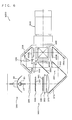
- FIG. 6 is a structural diagram of a projector equipped with the above-described illumination device.
- This projector 1000 comprises an illumination optical system 300, a color light separation optical system 380, a relay optical system 390, liquid-crystal panels 410R, 410G, 410B, a cross dichroic prism 420, and a projection lens 600 which is a projection optical system.
- the illumination optical system 300 is an integrator illumination optical system for almost uniformly illuminating the image formation regions of the liquid-crystal panels 410R, 410G, 410B and comprises the illumination device 100 of the above-described embodiment, a first lens array 320, a second lens array 340, a polarization conversion element array 360, and a superposition lens 370.
- the emitted light from behind the center of the light-emitting portion 11 of the light-emitting tube 10 is reflected by the main reflecting mirror 20 frontward of the illumination device 100.
- the emitted light from the zone in front of the center of the light-emitting portion 11 is reflected by the auxiliary reflecting mirror 30 and returned to the main reflecting mirror 20.
- This light is then reflected by the main reflecting mirror 20 frontward of the illumination device 100.
- the reflecting surface 32 of the auxiliary reflecting mirror 30 is formed with good accuracy, as was described hereinabove, the incident light can be reflected with good efficiency toward the main reflecting mirror 20.
- the light outgoing from the illumination device 100 enters the concave lens 200 and the propagation direction of the light is adjusted to be almost parallel to the optical axis of the illumination optical system 300.
- the parallelized light falls on each small lens 321 of the first lens array 320 and is split into a plurality of partial luminous fluxes whose number corresponds to the number of the small lenses 321. Furthermore, each partial luminous flux outgoing from the first lens array 320 falls on the second lens array 340 having small lenses 341 corresponding to each respective small lens 321.
- the outgoing light from the second lens array 340 falls on the polarization conversion element array 360 for adjusting into linearly polarized lights of the type with the same direction of polarization.
- a plurality of partial luminous fluxes with the polarization direction adjusted with the polarization conversion element array 360 enter the superposition lens 370, where each partial luminous flux falling on the liquid-crystal panels 410R, 410G, 410B is adjusted so as to be superimposed on the corresponding panel surface.
- the light outgoing from the superposition lens 370 is reflected with the reflecting mirror 372 and then falls on the color light separation optical system 380.
- the color light separation optical system 380 is an optical system for separating the light emitted from the illumination optical system 300 into color lights of three colors: red, green, and blue and comprises dichroic mirrors 382, 386 and a reflecting mirror 384.
- the first dichroic mirror 382 transmits the red color light component of the light outgoing from the superposition lens 370 and reflects the blue color light component and green color light component. Further, the red color light component passes through the first dichroic mirror 382, is reflected by the reflecting mirror 384, and reaches the liquid-crystal panel 410R for the red color light via a field lens 400R.
- the green color light component is reflected by the second dichroic mirror 386 and reaches the liquid-crystal panel 410G for the green color light via a field lens 400G.
- the relay optical system 390 is an optical system having a function of guiding the glue color light that passed through the dichroic mirror 386 of the color light separation optical system 380 to the liquid-crystal panel 410B and comprises an incoming-side lens 392, a relay lens 396, and reflecting mirrors 394, 398.
- the blue color light component passes through the incoming-side lens 392, reflecting mirror 394, relay lens 396, and reflecting mirror 398 and then reaches the liquid-crystal panel 410B for the blue color light via a field lens 400B.
- the relay optical system 390 is used for the blue color light in order to prevent the decrease in the light utilization efficiency caused by light scattering or the like, resulting from the fact that the length of the optical path of the blue color light is larger than the length of the optical path of other color lights.
- the relay optical system serves to transmit the partial luminous flux that fell on the incoming-side lens 392 directly to the field lens 400B.
- the relay optical system 390 has a configuration that transmits the blue color light of the three color lights, but it may be also configured to transmit other color lights, for example, the red color light.
- the three liquid-crystal panels 410R, 410G, 410B modulate each color light falling thereon according to the given image information and form the images of each color light. Further, polarizing plates are usually provided on the light incidence surface side and light outgoing surface side of each liquid-crystal panel 410R, 410G, 410B.
- the modulated light of each color light outgoing from each liquid-crystal panel 410R, 410G, 410B falls on the cross dichroic prism 420 serving as a color light synthesizing optical system for synthesizing those modulated lights and forming a color image.
- the cross dichroic prism 420 a dielectric multilayer film for reflecting the red color light and a dielectric multilayer film for reflecting the blue color light are formed in an almost X-like fashion on the boundary surfaces of four right prisms and the three color lights are synthesized by those dielectric multilayer films.
- the color image outgoing from the cross dichroic prism 420 is enlarged and projected on a screen with the projection lens 600.
- the projector 1000 in accordance with the present invention is not limited to the above-described embodiment and can be implemented in a variety of modes, without departing from the essence thereof.
- the following modifications are also possible.
- there were used two lens arrays 320, 340 for splitting the light from the illumination device 100 into a plurality of partial light fluxes but the present invention can be also applied to the projector which does not use such a lens array.
- a projector using transmission-type liquid-crystal panels was described as an example, but the present invention is not limited thereto and can be also applied to a projector using reflection-type liquid-crystal panels.
- a configuration including only liquid-crystal panels is possible and a pair of polarizing plates are not required.
- a cross dichroic prism is sometimes used as color light separation means for separating the illumination light into lights of three colors: red, green, and blue, and also as color light synthesizing means for synthesizing again the modulated lights of three colors and emitting them in the same direction.
- a dichroic prism combining a plurality of triangular or quadrangular rod-like dichroic prisms is used instead of the cross dichroic prism.
- the present invention When the present invention is applied to the projector using reflection-type liquid-crystal panels, it is possible to obtain the effect almost identical to that obtained with the projector using transmission-type liquid-crystal panels. Further, the projector using three liquid-crystal panels as modulation devices was explained as an example. However, the present invention can be also applied to a projector with a structure using one, two, four or more liquid-crystal panels.
- the light modulation device for modulating the incident light and generating an image is not limited to a liquid-crystal panel.
- it may be also a device using a micromirror.
- the lamp device in accordance with the present invention can be also employed in both the front projection-type projectors, in which image projection is conducted from the direction in which the projection surface is observed, and the rear projection-type projectors, in which image projection is conducted from the side opposite to the direction in which the projection surface is observed.
- An illumination device equipped with the auxiliary reflecting mirror manufactured by the manufacturing method in accordance with the present invention in the above-described manner can be widely employed as a light source for a projector or other various optical devices.
Landscapes
- Chemical & Material Sciences (AREA)
- Engineering & Computer Science (AREA)
- Materials Engineering (AREA)
- Organic Chemistry (AREA)
- Physics & Mathematics (AREA)
- General Physics & Mathematics (AREA)
- Life Sciences & Earth Sciences (AREA)
- Chemical Kinetics & Catalysis (AREA)
- General Chemical & Material Sciences (AREA)
- Geochemistry & Mineralogy (AREA)
- Manufacturing & Machinery (AREA)
- Optics & Photonics (AREA)
- Multimedia (AREA)
- Signal Processing (AREA)
- Combustion & Propulsion (AREA)
- Dispersion Chemistry (AREA)
- Mechanical Engineering (AREA)
- General Engineering & Computer Science (AREA)
- Projection Apparatus (AREA)
- Non-Portable Lighting Devices Or Systems Thereof (AREA)
- Optical Elements Other Than Lenses (AREA)
Priority Applications (1)
| Application Number | Priority Date | Filing Date | Title |
|---|---|---|---|
| EP06008094A EP1724615A3 (de) | 2004-03-01 | 2005-02-24 | Beleuctungseinheit und Bildwerfer |
Applications Claiming Priority (2)
| Application Number | Priority Date | Filing Date | Title |
|---|---|---|---|
| JP2004056548A JP3966298B2 (ja) | 2004-03-01 | 2004-03-01 | 反射鏡の製造方法、反射鏡、照明装置及びプロジェクタ |
| JP2004056548 | 2004-03-01 |
Related Child Applications (1)
| Application Number | Title | Priority Date | Filing Date |
|---|---|---|---|
| EP06008094A Division EP1724615A3 (de) | 2004-03-01 | 2005-02-24 | Beleuctungseinheit und Bildwerfer |
Publications (2)
| Publication Number | Publication Date |
|---|---|
| EP1571468A1 true EP1571468A1 (de) | 2005-09-07 |
| EP1571468B1 EP1571468B1 (de) | 2007-01-24 |
Family
ID=34747605
Family Applications (2)
| Application Number | Title | Priority Date | Filing Date |
|---|---|---|---|
| EP05004029A Expired - Lifetime EP1571468B1 (de) | 2004-03-01 | 2005-02-24 | Verfahren zur Herstellung eines Spiegels, eine Beleuctungseinheit und ein Bildwerfer |
| EP06008094A Withdrawn EP1724615A3 (de) | 2004-03-01 | 2005-02-24 | Beleuctungseinheit und Bildwerfer |
Family Applications After (1)
| Application Number | Title | Priority Date | Filing Date |
|---|---|---|---|
| EP06008094A Withdrawn EP1724615A3 (de) | 2004-03-01 | 2005-02-24 | Beleuctungseinheit und Bildwerfer |
Country Status (7)
| Country | Link |
|---|---|
| US (2) | US20050190558A1 (de) |
| EP (2) | EP1571468B1 (de) |
| JP (1) | JP3966298B2 (de) |
| KR (2) | KR100678807B1 (de) |
| CN (2) | CN100498049C (de) |
| DE (1) | DE602005000479T2 (de) |
| TW (1) | TWI281039B (de) |
Families Citing this family (8)
| Publication number | Priority date | Publication date | Assignee | Title |
|---|---|---|---|---|
| JP4193063B2 (ja) * | 2004-03-22 | 2008-12-10 | セイコーエプソン株式会社 | ランプ装置およびそれを備えたプロジェクタ |
| JP4972883B2 (ja) * | 2005-06-17 | 2012-07-11 | 株式会社日立製作所 | 光学ユニットおよび投射型映像表示装置 |
| JP4821514B2 (ja) * | 2006-08-30 | 2011-11-24 | セイコーエプソン株式会社 | 反射鏡の製造方法 |
| JP5266909B2 (ja) * | 2008-06-26 | 2013-08-21 | セイコーエプソン株式会社 | 放電ランプ、光源装置、及びプロジェクタ |
| CN101913757B (zh) * | 2010-08-12 | 2012-08-22 | 北京金格兰石英玻璃有限公司 | 球型石英玻璃棒的生产方法 |
| CN102463651A (zh) * | 2010-11-04 | 2012-05-23 | 茂杰光电有限公司 | 高精度太阳能反射镜的制造方法及其结构 |
| CN102476443A (zh) * | 2010-11-29 | 2012-05-30 | 比亚迪股份有限公司 | 灯罩吹塑模具装置和灯罩吹塑成型工艺 |
| KR101257445B1 (ko) * | 2011-04-25 | 2013-04-23 | 충북대학교 산학협력단 | 유리반사경 제작방법 |
Citations (3)
| Publication number | Priority date | Publication date | Assignee | Title |
|---|---|---|---|---|
| JPH0831382A (ja) * | 1994-07-13 | 1996-02-02 | Matsushita Electron Corp | 反射鏡付きメタルハライドランプ |
| US6557379B1 (en) * | 1999-10-28 | 2003-05-06 | Koito Manufacturing Co., Ltd. | Method of producing an arc tube |
| EP1450100A1 (de) * | 2002-08-30 | 2004-08-25 | Seiko Epson Corporation | Beleuchtungseinrichtung, scheinwerfer und zusammenbau-verfahren der beleuchtungseinrichtung |
Family Cites Families (10)
| Publication number | Priority date | Publication date | Assignee | Title |
|---|---|---|---|---|
| US3702395A (en) * | 1970-10-09 | 1972-11-07 | Us Navy | Condenser system for high intensity light source |
| US5143445A (en) * | 1989-10-10 | 1992-09-01 | General Electric Company | Glass reflectors lpcvd coated with optical interference film |
| JPH0817071B2 (ja) * | 1990-08-17 | 1996-02-21 | スタンレー電気株式会社 | 小型管球の製造方法 |
| JPH0562595A (ja) | 1991-08-30 | 1993-03-12 | Iwasaki Electric Co Ltd | 発光管の製造方法 |
| JPH0574418A (ja) * | 1991-09-10 | 1993-03-26 | Matsushita Electric Ind Co Ltd | 投射型液晶テレビ用光源装置 |
| JP3207022B2 (ja) * | 1992-11-24 | 2001-09-10 | 株式会社日立製作所 | 投射型表示装置用光源、照明装置および液晶投射型表示装置 |
| JPH09120067A (ja) | 1995-10-25 | 1997-05-06 | A G Technol Kk | 光源装置及びその応用装置 |
| JP2001125197A (ja) * | 1999-10-27 | 2001-05-11 | Matsushita Electric Ind Co Ltd | 光源装置、照明装置および投写型表示装置 |
| US6546752B2 (en) * | 1999-12-02 | 2003-04-15 | Fiberstars Incorporated | Method of making optical coupling device |
| US7159990B2 (en) * | 2003-08-18 | 2007-01-09 | Seiko Epson Corporation | Method of manufacturing reflective mirror, illumination device, and projector |
-
2004
- 2004-03-01 JP JP2004056548A patent/JP3966298B2/ja not_active Expired - Fee Related
-
2005
- 2005-02-05 TW TW094104102A patent/TWI281039B/zh not_active IP Right Cessation
- 2005-02-24 DE DE602005000479T patent/DE602005000479T2/de not_active Expired - Lifetime
- 2005-02-24 EP EP05004029A patent/EP1571468B1/de not_active Expired - Lifetime
- 2005-02-24 EP EP06008094A patent/EP1724615A3/de not_active Withdrawn
- 2005-02-28 KR KR1020050016355A patent/KR100678807B1/ko not_active Expired - Fee Related
- 2005-02-28 US US11/067,656 patent/US20050190558A1/en not_active Abandoned
- 2005-03-01 CN CNB2006101541880A patent/CN100498049C/zh not_active Expired - Fee Related
- 2005-03-01 CN CNB2005100515282A patent/CN1312495C/zh not_active Expired - Fee Related
-
2006
- 2006-08-28 KR KR1020060081746A patent/KR100737050B1/ko not_active Expired - Fee Related
-
2008
- 2008-12-15 US US12/334,963 patent/US8038325B2/en not_active Expired - Fee Related
Patent Citations (3)
| Publication number | Priority date | Publication date | Assignee | Title |
|---|---|---|---|---|
| JPH0831382A (ja) * | 1994-07-13 | 1996-02-02 | Matsushita Electron Corp | 反射鏡付きメタルハライドランプ |
| US6557379B1 (en) * | 1999-10-28 | 2003-05-06 | Koito Manufacturing Co., Ltd. | Method of producing an arc tube |
| EP1450100A1 (de) * | 2002-08-30 | 2004-08-25 | Seiko Epson Corporation | Beleuchtungseinrichtung, scheinwerfer und zusammenbau-verfahren der beleuchtungseinrichtung |
Non-Patent Citations (1)
| Title |
|---|
| PATENT ABSTRACTS OF JAPAN vol. 1996, no. 06 28 June 1996 (1996-06-28) * |
Also Published As
| Publication number | Publication date |
|---|---|
| CN1945110A (zh) | 2007-04-11 |
| DE602005000479T2 (de) | 2007-10-25 |
| TWI281039B (en) | 2007-05-11 |
| CN100498049C (zh) | 2009-06-10 |
| US20090097259A1 (en) | 2009-04-16 |
| US8038325B2 (en) | 2011-10-18 |
| KR20060043215A (ko) | 2006-05-15 |
| EP1724615A3 (de) | 2007-01-24 |
| KR20060099503A (ko) | 2006-09-19 |
| JP2005249877A (ja) | 2005-09-15 |
| US20050190558A1 (en) | 2005-09-01 |
| JP3966298B2 (ja) | 2007-08-29 |
| CN1664626A (zh) | 2005-09-07 |
| EP1571468B1 (de) | 2007-01-24 |
| EP1724615A2 (de) | 2006-11-22 |
| KR100678807B1 (ko) | 2007-02-05 |
| TW200532238A (en) | 2005-10-01 |
| KR100737050B1 (ko) | 2007-07-09 |
| DE602005000479D1 (de) | 2007-03-15 |
| CN1312495C (zh) | 2007-04-25 |
Similar Documents
| Publication | Publication Date | Title |
|---|---|---|
| US7461954B2 (en) | Lighting system, projector, and method for assembling lighting system | |
| US8038325B2 (en) | Method for manufacture of reflecting mirror, reflecting mirror, illumination device, and projector | |
| USRE42515E1 (en) | Method of manufacturing reflective mirror, illumination device, and projector | |
| JP3982552B2 (ja) | 光源装置、照明光学装置、プロジェクタ、および光源装置の製造方法 | |
| KR100685579B1 (ko) | 램프 장치 및 그것을 구비한 프로젝터 | |
| US7288899B2 (en) | Light source, projector, and method of driving arc tube | |
| JP2005148293A (ja) | 光源装置、光源装置の製造方法、及びプロジェクタ | |
| JP2005005183A (ja) | 高圧水銀ランプ、光源装置、およびプロジェクタ | |
| JP2001228538A (ja) | 液晶プロジェクタ装置 | |
| JP2010097702A (ja) | 光源装置、及びプロジェクタ | |
| JP4380382B2 (ja) | 光源装置、およびプロジェクタ | |
| JP3679696B2 (ja) | 画像表示光学ユニットにおける照明調整方法、画像表示光学ユニット、画像表示装置および画像表示システム | |
| JP4432735B2 (ja) | 光源装置、およびプロジェクタ | |
| WO2010050112A1 (ja) | 光源装置及びプロジェクタ | |
| JP2005283707A (ja) | ランプ装置の製造方法、ランプ装置並びにプロジェクタ | |
| JP2007227206A (ja) | 光源装置及びプロジェクタ |
Legal Events
| Date | Code | Title | Description |
|---|---|---|---|
| PUAI | Public reference made under article 153(3) epc to a published international application that has entered the european phase |
Free format text: ORIGINAL CODE: 0009012 |
|
| AK | Designated contracting states |
Kind code of ref document: A1 Designated state(s): AT BE BG CH CY CZ DE DK EE ES FI FR GB GR HU IE IS IT LI LT LU MC NL PL PT RO SE SI SK TR |
|
| AX | Request for extension of the european patent |
Extension state: AL BA HR LV MK YU |
|
| 17P | Request for examination filed |
Effective date: 20051027 |
|
| AKX | Designation fees paid |
Designated state(s): DE FR GB NL |
|
| GRAP | Despatch of communication of intention to grant a patent |
Free format text: ORIGINAL CODE: EPIDOSNIGR1 |
|
| RTI1 | Title (correction) |
Free format text: METHOD FOR MANUFACTURE OF A REFLECTING MIRROR, AN ILLUMINATION DEVICE, AND A PROJECTOR |
|
| GRAS | Grant fee paid |
Free format text: ORIGINAL CODE: EPIDOSNIGR3 |
|
| GRAA | (expected) grant |
Free format text: ORIGINAL CODE: 0009210 |
|
| AK | Designated contracting states |
Kind code of ref document: B1 Designated state(s): DE FR GB NL |
|
| PG25 | Lapsed in a contracting state [announced via postgrant information from national office to epo] |
Ref country code: NL Free format text: LAPSE BECAUSE OF FAILURE TO SUBMIT A TRANSLATION OF THE DESCRIPTION OR TO PAY THE FEE WITHIN THE PRESCRIBED TIME-LIMIT Effective date: 20070124 |
|
| REG | Reference to a national code |
Ref country code: GB Ref legal event code: FG4D |
|
| REF | Corresponds to: |
Ref document number: 602005000479 Country of ref document: DE Date of ref document: 20070315 Kind code of ref document: P |
|
| NLV1 | Nl: lapsed or annulled due to failure to fulfill the requirements of art. 29p and 29m of the patents act | ||
| ET | Fr: translation filed | ||
| PLBE | No opposition filed within time limit |
Free format text: ORIGINAL CODE: 0009261 |
|
| STAA | Information on the status of an ep patent application or granted ep patent |
Free format text: STATUS: NO OPPOSITION FILED WITHIN TIME LIMIT |
|
| 26N | No opposition filed |
Effective date: 20071025 |
|
| PGFP | Annual fee paid to national office [announced via postgrant information from national office to epo] |
Ref country code: FR Payment date: 20140211 Year of fee payment: 10 |
|
| PGFP | Annual fee paid to national office [announced via postgrant information from national office to epo] |
Ref country code: GB Payment date: 20140219 Year of fee payment: 10 |
|
| PGFP | Annual fee paid to national office [announced via postgrant information from national office to epo] |
Ref country code: DE Payment date: 20140417 Year of fee payment: 10 |
|
| REG | Reference to a national code |
Ref country code: DE Ref legal event code: R119 Ref document number: 602005000479 Country of ref document: DE |
|
| GBPC | Gb: european patent ceased through non-payment of renewal fee |
Effective date: 20150224 |
|
| REG | Reference to a national code |
Ref country code: FR Ref legal event code: ST Effective date: 20151030 |
|
| PG25 | Lapsed in a contracting state [announced via postgrant information from national office to epo] |
Ref country code: DE Free format text: LAPSE BECAUSE OF NON-PAYMENT OF DUE FEES Effective date: 20150901 Ref country code: GB Free format text: LAPSE BECAUSE OF NON-PAYMENT OF DUE FEES Effective date: 20150224 |
|
| PG25 | Lapsed in a contracting state [announced via postgrant information from national office to epo] |
Ref country code: FR Free format text: LAPSE BECAUSE OF NON-PAYMENT OF DUE FEES Effective date: 20150302 |