EP1571761A2 - Mise en forme de faisceaux d'un réseau d'antennes - Google Patents
Mise en forme de faisceaux d'un réseau d'antennes Download PDFInfo
- Publication number
- EP1571761A2 EP1571761A2 EP04255115A EP04255115A EP1571761A2 EP 1571761 A2 EP1571761 A2 EP 1571761A2 EP 04255115 A EP04255115 A EP 04255115A EP 04255115 A EP04255115 A EP 04255115A EP 1571761 A2 EP1571761 A2 EP 1571761A2
- Authority
- EP
- European Patent Office
- Prior art keywords
- mobile station
- array antenna
- interference
- distance
- station acting
- Prior art date
- Legal status (The legal status is an assumption and is not a legal conclusion. Google has not performed a legal analysis and makes no representation as to the accuracy of the status listed.)
- Granted
Links
Images


Classifications
-
- H—ELECTRICITY
- H04—ELECTRIC COMMUNICATION TECHNIQUE
- H04B—TRANSMISSION
- H04B7/00—Radio transmission systems, i.e. using radiation field
- H04B7/02—Diversity systems; Multi-antenna system, i.e. transmission or reception using multiple antennas
- H04B7/04—Diversity systems; Multi-antenna system, i.e. transmission or reception using multiple antennas using two or more spaced independent antennas
- H04B7/06—Diversity systems; Multi-antenna system, i.e. transmission or reception using multiple antennas using two or more spaced independent antennas at the transmitting station
- H04B7/0613—Diversity systems; Multi-antenna system, i.e. transmission or reception using multiple antennas using two or more spaced independent antennas at the transmitting station using simultaneous transmission
- H04B7/0615—Diversity systems; Multi-antenna system, i.e. transmission or reception using multiple antennas using two or more spaced independent antennas at the transmitting station using simultaneous transmission of weighted versions of same signal
- H04B7/0617—Diversity systems; Multi-antenna system, i.e. transmission or reception using multiple antennas using two or more spaced independent antennas at the transmitting station using simultaneous transmission of weighted versions of same signal for beam forming
-
- H—ELECTRICITY
- H04—ELECTRIC COMMUNICATION TECHNIQUE
- H04B—TRANSMISSION
- H04B7/00—Radio transmission systems, i.e. using radiation field
- H04B7/02—Diversity systems; Multi-antenna system, i.e. transmission or reception using multiple antennas
- H04B7/04—Diversity systems; Multi-antenna system, i.e. transmission or reception using multiple antennas using two or more spaced independent antennas
- H04B7/08—Diversity systems; Multi-antenna system, i.e. transmission or reception using multiple antennas using two or more spaced independent antennas at the receiving station
- H04B7/0837—Diversity systems; Multi-antenna system, i.e. transmission or reception using multiple antennas using two or more spaced independent antennas at the receiving station using pre-detection combining
- H04B7/0842—Weighted combining
- H04B7/086—Weighted combining using weights depending on external parameters, e.g. direction of arrival [DOA], predetermined weights or beamforming
Definitions
- the present invention relates to a method for forming a beam of an array antenna and an apparatus therefor, and, in particular, to a method for forming a beam of an array antenna with the use of a null forming method, and an apparatus therefor.
- the present invention particularly relates to the latter method.
- FIG. 1 shows a block diagram of an apparatus employing the null forming method according to the related art.
- a weight vector W T for transmission beam forming given to multipliers 12 1 through 12 n is expressed as
- a weight vector W R for reception beam forming given to multipliers 14 1 through 14 n is expressed by
- An arrival direction estimation part 16 estimates a path arrival direction (DoA: Direction of Arrival), from a mobile station acting as interference.
- DoA Direction of Arrival
- a convergence algorithm part 18 operates a convergence algorithm such as that of a steepest descent method (LMS: Least Mean Squire) based on the path arrival direction DoA, and carries out reception null forming. Thereby, the weight vector W T for transmission beam forming and the weight vector W R for reception beam forming are generated. Output signals of the multipliers 14 1 through 14 n are added together by an adding part 20 and the addition result is output.
- LMS steepest descent method
- FIG. 2 shows a beam pattern at a base station in a case where a mobile station #2 acting as interference with respect to a desired mobile station #1, and null forming is carried out such that a null point may be directed toward the mobile station #2.
- P Ti denotes a transmission power from a mobile station i
- P G ( ⁇ i ) denotes a beam gain in an arrival direction ⁇ i
- P ATT (r i ) denotes a distance attenuation amount for a distance r i .
- angle velocities i.e., phase changes ⁇ 2a and ⁇ 2b for respective distances r sa and r 2b between the base station and mobile station #2 are different from one another, as shown in FIG. 3 ( ⁇ 2a ⁇ ⁇ 2b ).
- FIG. 3 shows a circumferential direction in which the phase change becomes maximum for the purpose of simplification, it is not necessary to limit thereto.
- the moving speed vector V may have an arbitrary value, and also, there is no limitation to a position of the mobile station.
- the moving speed is assumed to be fixed for the purpose of comparative explanation, generality is maintained even if the moving speed changes at respective positions.
- description is made assuming that only the mobile station acting as interference moves for the purpose of simplification of description, the same discussion can be applied, by considering a relative speed of the mobile station #2 with respect to the mobile station #1 even in a case where rather the mobile station #1 which is a desired one moves.
- Japanese Laid-open Patent Application No. 2001-251233 discloses a use of an arrival direction DoA required in receiving, for transmission beam forming in an FDD system using different frequencies for uplink and downlink channels.
- Japanese Laid-open Patent Application No. 2001-203630 discloses forming a beam with DoA information, estimating of a position of a mobile station, estimating a traffic therewith as well as DoA information, further forming a beam in a direction in which the traffic is large, and thereby, reducing call collision probability at a time of random access.
- Japanese Laid-open Patent Application No. 8-285934 discloses detecting an interference station by collecting information from all the directions at a time of intermittent reception, and carrying out null forming.
- Japanese Laid-open Patent Application No. 2000-505254 and Japanese Laid-open Patent Application No. 2002-523969 disclose null forming.
- Japanese Laid-open Patent Application No. 2003-92548, Japanese Laid-open Patent Application No. 2003-87189 and Japanese Laid-open Patent Application No. 2003-92549 disclose methods of calibration for an adaptive array antenna.
- Japanese Laid-open Patent Application No. 2002-508889 discloses beam forming between an own station which receives influence from a new terminal and a terminal with which communication has been already made, when the new terminal for which communication is made newly occurs.
- Japanese Laid-open Patent Application No. 2003-51775 discloses forming a null for an interference station, and carrying out steering the thus-formed beam according to a least mean square method.
- Japanese Laid-open Patent Application No. 2002-359588 discloses calculating an initial value of beam forming for a terminal for which communication is newly carried out, with the use of beam information for a terminal with which communication has been already carried out, and improving a beam initial pull-in speed.
- null point is produced in a fixed beam in a direction of the mobile station #2, and steering for the mobile station #2 is carried out.
- null forming performance is determined based on steering performance around the base station.
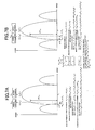
- Beam gain changing amounts ⁇ P G2a and ⁇ P G2b in the base station after respective phase changes ⁇ 2a and ⁇ 2b are such that, as shown in FIGS. 4 and 5, the mobile station #2b existing around the base station has the larger value ( ⁇ P G2b ), and the received power from the interference station in the base station is larger from the mobile station #2b.
- the SIRs in the base station are expressed by the following formula after the movement: SIR 1 (P T1 , P T2a , ⁇ 1 , ⁇ 2a , r 1 , r 2a ) >> SIR 1 (P T1 , P T2b , ⁇ 1 , ⁇ 2b , r 1 , r 2b )
- null steering performance responding to a phase change amount determined from a distance between the base station and the mobile station is required. Accordingly, characteristic deterioration may occur when the mobile station moves at a high speed around the base station with insufficient steering performance.
- a degree of sharp falling at a null point i.e., a null width is set as being minimum which can be produced by a number of antenna elements given, such that received power at a cell edge (reception quality: the same in the SIR) may be not less than a system design, and thereby, maximization of a cell radius is achieved.
- a phase change amount is small at a cell edge at a time of high speed movement as mentioned above, and, therefrom, it can be seen that complete complementary relationship holds between the null width and the distance between the base station and the mobile station, i.e., the phase change amount. That is, the phase change amount is small when the beam width is small, and, in other words, in a case of long distance communication.
- the phase change amount is large, and, the beam width should not be set to be a minimum value, in other words, it is not necessary to generate a null point in a sharp manner. This is because a required reception quality can be obtained even when the null point should not be formed so sharply.
- the present invention has been devised in consideration of the above-mentioned matter, and an object of the present invention is to provide a method of beam forming in an array antenna and an apparatus therefor by which it is possible to steer for a mobile station even it moves at high speed at any position within a cell.
- beam forming is carried out in such a manner that a signal power to interference power ratio may be fixed between before and after the movement without regard to the distance.
- a beam width is adaptively changed, and thereby, it is possible to steer for a mobile station which moves at a high speed at any position within a cell.
- beam forming is carried out in such a manner that a total sum of signal power to interference power ratios obtained when the mobile station acting as interference moves during a predetermined time interval may be fixed between before and after the movement without regard to the distance.
- a beam width is adaptively changed, and thereby, it is possible to steer for a mobile station which moves at a high speed at any position within a cell.
- a third aspect of the present invention by estimating the distance of the mobile station acting as interference from received power from the mobile station acting as interference from a single antenna of the array antenna, it is possible to know the distance of the mobile station acting as interference, which is applied to the invention described above for the beam forming.
- FIG. 6 shows a block diagram of a first embodiment of an array antenna apparatus according to the present invention.
- the apparatus employs N non-directional antennas 30 1 through 30 n , a weight vector W T for forming a beam for transmission, given to multipliers 32 1 through 32 n is expressed as
- a weight control part 36 operates a convergence algorithm such as that of a steepest descent method (LMS: Least Mean Squire) or such based on moving direction information ⁇ i from moving speed information (an absolute value of a moving speed vector
- LMS Least Mean Squire
- each mobile station has a GPS (global positioning system) receiving part, obtains positional information of the own station therefrom, and transmits the positional information to the base station periodically.
- the base station calculates, from change in the received positional information of each mobile station, the moving speed information, the moving direction information and the distance between the mobile station and the base station.
- Output signals from the multipliers 34 1 through 34 n are added together in an adding part 38.
- the null control rule according to the present invention is also applied for transmission null forming as it is.
- FIGS. 7A and 7B a first embodiment of a weight control algorithm according to the present invention carried out by the weight control part 36 is described.
- received power in a mobile station #1 is expressed by P T1 - P ATT (r 1 + P G ( ⁇ 1 ).
- P Ti denotes transmission power from a mobile station #i
- P G ( ⁇ i ) denotes a beam gain in an arrival direction ⁇ i
- P ATT (r i ) denotes a distance attenuation amount for a distance r i .
- SIR 3 is P T2a - P ATT (r 2a ), and received power (after movement) from the mobile station #2a is P T2a - P ATT (r 2a ) + ⁇ P G2a .
- received power from the mobile station #1 is expressed by P T1 - P ATT (r 1 ) + P G ( ⁇ 1 ).
- Received power (before the movement) from the mobile station #2b is P T2b - P ATT (r 2b )
- received power (after the movement) of the mobile station #2b is P T2b - P ATT (r 2b ) + ⁇ P G2b .
- FIG. 8 shows a flow chart of the weight control processing according to the first embodiment carried out by the weight control part 36 shown in FIG. 6.
- Step S1 the moving speed information
- Step S2 received power for the desired mobile station #1 is calculated with a current weight.
- Step S3 current SIR is calculated from the received power from the mobile station #1 and the received power from the mobile station #i.
- Step S6 When the current SIR is not identical to the SIR in the previous condition, the weight is updated in Step S6, and the current operation flow returns to Step S2. Steps S2 through S6 are then repeated.
- the operation flow is proceeded with from Step S5 to Step S7. Then, the current SIR is held as new SIR in the previous condition. After that, the current weight is output in Step S8, and the current processing is finished.
- the received power from the mobile station #1 is expressed by P T1 - P ATT (r 1 ) + P G ( ⁇ 1 ), the received power (before the movement) from the mobile station #2a shown in FIG. 3 is P T2a - P ATT (r 2a ), and the received power (after the movement) from the mobile station #2a is P T2a - P ATT (r 2a ) + ⁇ P G2a .
- a total sum Sa of the SIRs for a moving section is expressed by the following formula (2):
- the received power from the mobile station #1 is expressed by P T1 - P ATT (r 1 ) + P G ( ⁇ 1 ), the received power (before the movement) from the mobile station #2b is P T2b - P ATT (r 2b ), and the received power (after movement) of the mobile station #2b is P T2b - P ATT (r 2b ) + ⁇ P G2b .
- a total sum Sb of the SIRs for a moving section is expressed by the following formula (3):
- the beam width for the null point is narrowed and falling of the beam is made sharp in a case where the distance r i is large (for example, at a cell edge), while, the beam width for the null point is widen and falling of the beam is made gentle in a case where the distance r i is small (for example, around the base station).
- the steering performance is maintained at a constant level, and thus, stable operation is achieved even under a condition of high speed movement of the mobile station.
- FIG. 10 shows a block diagram of a second embodiment of an array antenna apparatus according to the present invention.
- N non-directional antennas 30 1 through 30 n are used, a weight vector W T for transmission beam forming given to multipliers 32 1 through 32 n is expressed by
- a received signal of the omni (non-directional) antenna is supplied to a received power measurement part 40 1 .
- received power from each mobile station is measured, the distance attenuation amount P ATT (r i ) and the distance r i are estimated, and are supplied to the weight control part 36.
- Separation of received signals from the respective mobile stations is carried out by a method depending on a multiplexing method applied, and, for example, in a case of CDMA, a spreading code assigned for each mobile station is used and de-spreading is carried out for this purpose.
- the distance attenuation amount P ATT (r i ) is approximated by Po + ⁇ x 10 log(r i ).
- Po denotes an attenuation amount [dB] at a cell edge
- ⁇ denotes a constant applied to a distance attenuation rule.
- a correction term may be applied depending on an actual operation environment at a time of cell design, and, a distance is estimated from the distance attenuation amount.
- the weight control part 36 operates a convergence algorithm such as a steepest descent method (LMS: Least Mean Squire) or such based on the moving direction information ⁇ i from the moving speed information (the absolute value of a moving speed vector
- LMS Least Mean Squire
- each mobile station has a GPS (global positioning system) receiving part, obtains positional information of the own station therefrom, and transmits the positional information to the base station periodically.
- the base station calculates, from change in the received positional information of each mobile station, the moving speed information and the moving direction information.
- the received signal from the single antenna 30 1 is supplied to the received power measurement part 40 1 and the distance r i is estimated.
- an antenna having the maximum received power may be selected from among the antennas 30 1 through 30 n , and the distance r i may be estimated form the received signal therefrom.
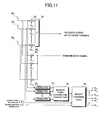
- FIG. 11 shows a block diagram of a third embodiment of an array antenna apparatus according to the present invention.
- N non-directional antennas 30 1 through 30 n are used, a weight vector W T for transmission beam forming given to multipliers 32 1 through 32 n is expressed by
- Received signals from the N antennas 30 1 through 30 n before weighting are supplied to received power measurement parts 42 1 through 42 n , received power from each mobile station is measured by each of the received power measurement parts 42 1 through 42 n , the thus-obtained measurement values are combined/averaged by a received power combination/average part 44, the distance attenuation amount P ATT (r i ) and the distance r i are estimated with the use of the thus-obtained averaged received power, and the thus-obtained information is supplied to the weight control part 36.
- the received signals from only m (m ⁇ N) antennas may be combined/averaged instead of the same processing with the use of the signals from all the N antennas.
- the weight control part 36 then operates a convergence algorithm such as a steepest descent method (LMS: Least Mean Squire) or such based on the moving direction information ⁇ i from the moving speed information (the absolute value of a moving speed vector
- LMS Least Mean Squire
- each mobile station has a GPS (global positioning system) receiving part, obtains positional information of the own station therefrom, and transmits the positional information to the base station periodically.
- the base station calculates, from change in the received positional information of each mobile station, the moving speed information and the moving direction information.
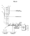
- FIG. 12 shows a block diagram of a fourth embodiment of an array antenna apparatus according to the present invention.
- N non-directional antennas 30 1 through 30 n are used, a weight vector W T for transmission beam forming given to multipliers 32 1 through 32 n is expressed by
- a received signal from an omni (non-directional) antenna 30 1 is supplied to an FFT part 46, which then performs FFT (Fast Fourier Transform), and thereby, a frequency component thereof is obtained, and a maximum Doppler frequency is estimated.
- the moving speed information an absolute value
- the received signal from the omni antenna receives influence from an actual propagation characteristic itself before the directivity thereof is narrowed. Therefore, by carrying out FFT on the received signal, a frequency power spectrum can be observed.
- a general reception environment on the side of a mobile station i.e., a Jake's model which is a spectrum when a path arrival direction is achromatic (i.e., equal path arrival from 360 °) is obtained.
- the weight control part 36 then operates a convergence algorithm such as a steepest descent method (LMS: Least Mean Squire) or such based on the moving direction information ⁇ i from the moving speed information (the absolute value of a moving speed vector
- LMS Least Mean Squire
- each mobile station has a GPS (global positioning system) receiving part, obtains positional information of the own station therefrom, and transmits the positional information to the base station periodically.
- the base station calculates, from change in the received positional information of each mobile station, the moving speed information, the moving direction information and the distance between the base station and the mobile station.
- the received signal from the single antenna 30 1 is supplied to the FFT part 46, and therewith, the moving speed v i is estimated.
- an antenna having the maximum received power may be selected from among the antennas 30 1 through 30 n , and the received signal therefrom may be used for the same purpose.
- FIG. 13 shows a block diagram of a fifth embodiment of an array antenna apparatus according to the present invention.
- N non-directional antennas 30 1 through 30 n are used, a weight vector W T for transmission beam forming given to multipliers 32 1 through 32 n is expressed by
- Received signals from the N antennas 30 1 through 30 n before weighting are supplied to FFT parts 46 1 through 46 n , respectively, each of which then performs FFT (Fast Fourier Transform), a frequency combination/average part 54 combines and averages the thus-obtained frequency components, and a maximum Doppler frequency is estimated therefrom. That is, the maximum value f max is detected from the thus-averaged frequency component in a maximum frequency detection part 48. Thus, the Doppler frequency f d is obtained. Then, a moving speed estimation part 50 obtains the moving speed v i from the above-mentioned formula (5), and supplies it to the weight control part 36. Frequency components of the received signals from m (m ⁇ N) antennas may be combined and averaged instead of those from all the N antennas.
- the weight control part 36 then operates a convergence algorithm such as a steepest descent method (LMS: Least Mean Squire) or such based on the moving direction information ⁇ i from the moving speed information (the absolute value of a moving speed vector
- LMS Least Mean Squire
- each mobile station has a GPS (global positioning system) receiving part, obtains positional information of the own station therefrom, and transmits the positional information to the base station periodically.
- the base station calculates, from change in the received positional information of each mobile station, the moving speed information and the moving direction information.
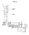
- FIG. 14 shows a block diagram of a sixth embodiment of the present invention
- FIG. 15 illustrates an embodiment of the weight control algorithm therefor.
- N non-directional antennas 30 1 through 30 n are used, a weight vector W T for transmission beam forming given to multipliers 32 1 through 32 n is expressed by
- the weight control part 36 operates a convergence algorithm such as a steepest descent method (LMS: Least Mean Squire) or such based on the moving direction information ⁇ i from the moving speed information (the absolute value of a moving speed vector
- LMS Least Mean Squire
- each mobile station has a GPS (global positioning system) receiving part, obtains positional information of the own station therefrom, and transmits the positional information to the base station periodically.
- the base station calculates, from change in the received positional information of each mobile station, the moving speed information, the moving direction information and the distance between the base station and the mobile station.
- a plurality of samples are stored in a memory part 58 for the moving speed information
- the mobile station #2 acting as interference moves on the concentric circle.
- generalization is possible also for a case where the distance changes, or rather the desired mobile station #1 moves.
- a moving speed and moving direction estimation part 60 estimates the moving speed
- the weight estimation part 62 estimates a path arrival direction DoA of the mobile station #i acting as interference from the estimated moving speed
- LMS Least Mean Squire
- the arrival angle comparing part 56 obtains the difference ⁇ n between the estimated moving direction ⁇ E ⁇ (n) of the beam's null point and the moving direction information ⁇ (n) of the beam's null point calculated from the actual weight control information, compares it with the threshold value ⁇ th , and supplies the comparison result to a weight determining part 64.
- the weight determining part 64 selects the weight vector W T for forming a transmission beam and the weight vector W R for forming a reception beam obtained from the weight control part 36, and output them, while, the weight determining part 64 selects the weight vector W T for forming a transmission beam and the weight vector W R for forming a reception beam obtained from the weight estimation part 62 when ⁇ n ⁇ ⁇ th , and output the same.
- FIG. 16 shows a flow chart of the weight control processing carried out in the apparatus shown in FIG. 14.
- the weight control part 36 reads the moving speed information
- current SIR is calculated from the received power from the mobile station #1 and the received power from the mobile station #i, and, in Step S15, it is determined whether or not the current SIR is same as SIR in the previous state.
- Step S16 When the current SIR is not identical to the SIR in the previous state, the weight is updated in Step S16, the processing is proceeded with to Step S12, and Steps S12 through S16 are repeated.
- the current SIR becomes equal to the SIR in the previous state, the current SIR is held as new SIR in the previous state, and, then, in Step S18, the moving direction information ⁇ i is calculated.
- Step S20 the moving speed information
- Step S22 from the estimated moving speed
- Step S23 it is determined whether or not the difference ⁇ n between the estimated moving direction ⁇ E ⁇ (n) of the beam's null point and the moving direction information ⁇ (n) calculated from the actual weight information exceeds the threshold value ⁇ th . Then, when ⁇ n ⁇ ⁇ th , the processing is proceeded with to Step S24, and the weight vector W T for forming a transmission beam and the weight vector W R for forming a reception beam estimated in Step S22 are selected and output.
- Step S25 the processing is proceeded with to Step S25, and the weight vector W T for forming a transmission beam and the weight vector W R for forming a reception beam updated in Step S16 are selected, and are output.
- FIG. 17 shows a block diagram of a seventh embodiment of an array antenna apparatus according to the present invention.
- a weight correction part 66 is provided to the weight correction part 66.
- the weight vector W T for forming a transmission beam, the weight vector W R for forming a reception beam and the moving direction information ⁇ i are provided from the weight control part 36.
- the weight estimation part 62 estimates the weight vector W T for forming a transmission beam and the weight vector W R for forming a reception beam from the estimated moving speed
- the weight correction part 66 obtains a difference ⁇ n between the estimated moving direction ⁇ E ⁇ (n) of the beam's null point and the moving direction ⁇ (n) of the beam's null point calculated from the actual weight control information, compares it with the threshold ⁇ th , and, when ⁇ n ⁇ ⁇ th , the weight correction part 66 multiplies the difference ⁇ n with a predetermined correction coefficient, which is then supplied to the weight control part 36 as a correction value in a feedback manner.
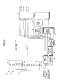
- FIG. 18 shows a block diagram of an eight embodiment of an array antenna apparatus according to the present invention
- FIGS. 19A and 19B illustrate a weight control algorithm therefor.
- N non-directional antennas 30 1 through 30 n are used, a weight vector W T for transmission beam forming given to multipliers 32 1 through 32 n is expressed by
- the weight control part 36 operates a convergence algorithm such as that according to a steepest descent method (LMS: Least Mean Squire) or such based on the moving direction ⁇ i information from the moving speed information (the absolute value of a moving speed vector
- LMS Least Mean Squire
- each mobile station has a GPS (global positioning system) receiving part, obtains positional information of the own station therefrom, and transmits the positional information to the base station periodically.
- the base station calculates, from change in the received positional information of each mobile station, the moving speed information, the moving direction information and the distance between the base station and the mobile station.
- , the moving direction information ⁇ i of the mobile station #i and the distance r i between the base station and the mobile station supplied to the weight control part 36 are also supplied to and stored in the memory part 58.
- a moving speed and moving direction estimation part 60 estimates the moving speed
- the weight estimation part 62 estimates the path arrival direction DoA of the mobile station #i acting as interference from the estimated moving speed
- LMS Least Mean Squire
- the arrival angle comparing part 56 obtains a difference ⁇ n between the estimated moving direction ⁇ E ⁇ (n) of the beam's null point and the moving direction information ⁇ (n) of the beam's null point calculated from the actual weight control information, compares it with the threshold value ⁇ th , and supplies the comparison result to the weight determining part 72.
- the weight determining part 72 selects the weight vector W T for forming a transmission beam and the weight vector W R for forming a reception beam obtained from the weight control part 36, and output them, while, when ⁇ n ⁇ ⁇ th the weight determining part 72 selects the weight vector W T for forming a transmission beam and the weight vector W R for forming a reception beam obtained from the weight estimation part 62, and output the same.
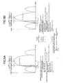
- an interference power suppression amount ⁇ P due to a difference in a null point occurring depending on the distance r i between the base station and the mobile station differs, and the present embodiment responds thereto.
- the interference power suppression amount ⁇ P 2a becomes larger since the beam width is narrow when the distance r i becomes larger, as shown in FIG. 19A.
- the distance r i becomes smaller, as shown in FIG. 19B, since the beam width is wider, the interference power suppression amount ⁇ P 2a becomes smaller.
- the estimated weight angle and power calculation part 68 obtains an arrival angle (null point) of the interference station according to the output weight from the weight control part 36, and, calculates the interference power suppression amount ⁇ P n according to the estimated weight from the weight estimation part 62 for this null point.
- the power comparing part 70 determines whether or not the interference power suppression amount ⁇ P n exceeds the threshold value ⁇ P th , and then, provides the determination result to the weight determining part 72.
- the weight determining part 72 selects the output of the weight control part 36, while, when the interference power suppression amount ⁇ P b exceeds the threshold value ⁇ P th , the weight determining part 72 selects the output of the weight estimation part 62, and the weight determining part 72 uses the thus-selected one as the updated weight.
- FIG. 20 shows a block diagram of a ninth embodiment of an array antenna apparatus according to the present invention.
- a weight correction part 74 is provided to the weight correction part 74.
- the weight vector W T for forming a transmission beam, the weight vector W R for forming a reception beam and the moving direction information ⁇ i are provided from the weight control part 36.
- the weight estimation part 62 estimates the weight vector W T for forming a transmission beam and the weight vector W R for forming a reception beam from the estimated moving speed
- FIG. 21 shows a block diagram of a tenth embodiment of an array antenna apparatus according to the present invention.
- a weight vector W T for transmission beam forming given to multipliers 32 1 through 32 n is expressed by
- a weight vector W R for reception beam forming given to multipliers 34 1 through 34 n is expressed by
- the weight control part 36 operates a convergence algorithm such as that according to a steepest descent method (LMS: Least Mean Squire) or such based on the moving direction information ⁇ i from the moving speed information (the absolute value of a moving speed vector
- LMS Least Mean Squire
- each mobile station has a GPS (global positioning system) receiving part, obtains positional information of the own station therefrom, and transmits the positional information to the base station periodically.
- the base station calculates, from change in the received positional information of each mobile station, the moving speed information, the moving direction information and the distance between the base station and the mobile station.
- , the moving direction information ⁇ i of the mobile station #i and the distance r i between the base station and the mobile station supplied to the weight control part 36 are also supplied to and stored in the memory part 58.
- the moving speed and moving direction estimation part 60 estimates the moving speed
- the initial weight generation part 80 estimates a path arrival direction DoA of the mobile station acting as interference from the estimated moving speed
- , the estimated moving direction ⁇ E ⁇ i and the distance r i (it is obvious that the distance r i between the base station and the mobile station at the time of handed over r max ), carries out reception null forming based on the path arrival direction DoA, generates initial values of a weight vector W T for forming a transmission beam and a weight vector W R for forming a reception beam, and provides them to the weight control part 36 in the cell #B.
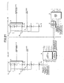
- FIG. 22 shows a block diagram of an eleventh embodiment of an array antenna apparatus according to the present invention.
- N non-directional antennas 30 1 through 30 n are used, a weight vector W T for transmission beam forming given to multipliers 32 1 through 32 n is expressed by
- An arrival angle estimation part 82 estimates a path arrival direction DoA of a mobile station #i acting as interference, and supplies the thus-estimated DoA value to the weight control part 36.
- the weight control part 36 operates a convergence algorithm such as that according to a steepest descent method (LMS: Least Mean Squire) or such, with the estimated path arrival direction DoA of the mobile station acting as interference as an initial value, based on the moving direction information ⁇ i , from the moving speed information (the absolute value of a moving speed vector
- LMS Least Mean Squire
- each mobile station has a GPS (global positioning system) receiving part, obtains positional information of the own station therefrom, and transmits the positional information to the base station periodically.
- the base station calculates, from change in the received positional information of each mobile station, the moving speed information, the moving direction information and the distance between the base station and the mobile station.
- Output signals of the multipliers 34 1 through 34 n are added together by an adding part 38, and the addition result is output.
- the null control rule according to the present invention is applicable as it is also for transmission null forming.
- the arrival direction estimation part 82 estimates the path arrival direction DoA of the mobile station acting as interference, and the estimated DoA value is used as an initial value in the weight control part 36. Thereby, convergence of the reception null forming can be achieved within a shorter time.
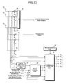
- FIG. 23 shows a block diagram of a twelfth embodiment of an array antenna apparatus according to the present invention.
- N non-directional antennas 30 1 through 30 n are used, a weight vector W T for transmission beam forming given to multipliers 32 1 through 32 n is expressed by
- An arrival angle estimation part 82 estimates a path arrival direction DoA of a mobile station #i acting as interference, and supplies the thus-estimated DoA value to the weight control part 36.
- the weight control part 36 operates a convergence algorithm such as that according to a steepest descent method (LMS: Least Mean Squire) or such, with the estimated path arrival direction DoA of the mobile station acting as interference as an initial value, based on the moving direction information ⁇ i , from the moving speed information (the absolute value of a moving speed vector
- LMS Least Mean Squire
- each mobile station has a GPS (global positioning system) receiving part, obtains positional information of the own station therefrom, and transmits the positional information to the base station periodically.
- the base station calculates, from change in the received positional information of each mobile station, the moving speed information, the moving direction information and the distance between the base station and the mobile station.
- Output signals of the multipliers 34 1 through 34 n are added together by the adding part 38, and the addition result is output.
- the null control rule according to the present invention is applicable as it is for transmission null forming.
- a convergence algorithm part 84 compares a result obtained from multiplying received signals from the antennas 30 1 through 30 n with the primary weight vector W 1R supplied from the weight control part 36, with a known reference signal read out from a replica storage part 86, carries out reception null forming by obtaining a convergence according to a convergence algorithm such as that according to a steepest descent method (LMS) or such, and generates a weight vector W T for forming a transmission beam and a weight vector W R for forming a reception beam.
- LMS steepest descent method
- the convergence algorithm is operated twice, it becomes possible to achieve a convergence of the weight vector W T for forming a transmission beam and the weight vector W R for forming a reception beam within a shorter time.
- the weight control part 36 acts as a weight control part; the received power estimation parts 40 1 , 42 1 through 42 n , and the received power combination/average part 44 act as a distance estimation part; the FFT part 46, 52 1 through 52 n , frequency combination/average part 54, the maximum frequency detection part 48 and the moving speed estimating part 50 act as a moving speed estimation part; the memory part 58 and the moving speed and moving direction estimation part 60 act as a null point estimation part; the arrival angle comparing part 56 and the weight determining part 84 act as an initial value setting part; the weight correction part 66 acts as a feedback part; the initial weight generation part 80 acts as a handover initial value setting part; the arrival direction estimation part 82 acts as a path arrival direction estimation part; and the convergence algorithm part 84 and the replica storage part 86 act as a converging part.
Landscapes
- Engineering & Computer Science (AREA)
- Computer Networks & Wireless Communication (AREA)
- Signal Processing (AREA)
- Variable-Direction Aerials And Aerial Arrays (AREA)
- Mobile Radio Communication Systems (AREA)
- Radio Transmission System (AREA)
Applications Claiming Priority (2)
| Application Number | Priority Date | Filing Date | Title |
|---|---|---|---|
| JP2004056522 | 2004-03-01 | ||
| JP2004056522A JP4280657B2 (ja) | 2004-03-01 | 2004-03-01 | アレーアンテナのビーム形成方法及びその装置 |
Publications (3)
| Publication Number | Publication Date |
|---|---|
| EP1571761A2 true EP1571761A2 (fr) | 2005-09-07 |
| EP1571761A3 EP1571761A3 (fr) | 2008-01-23 |
| EP1571761B1 EP1571761B1 (fr) | 2016-04-13 |
Family
ID=34747603
Family Applications (1)
| Application Number | Title | Priority Date | Filing Date |
|---|---|---|---|
| EP04255115.0A Expired - Lifetime EP1571761B1 (fr) | 2004-03-01 | 2004-08-25 | Mise en forme de faisceaux d'un réseau d'antennes |
Country Status (3)
| Country | Link |
|---|---|
| US (1) | US7629927B2 (fr) |
| EP (1) | EP1571761B1 (fr) |
| JP (1) | JP4280657B2 (fr) |
Families Citing this family (13)
| Publication number | Priority date | Publication date | Assignee | Title |
|---|---|---|---|---|
| KR100723804B1 (ko) * | 2004-12-15 | 2007-05-31 | 삼성전자주식회사 | 스마트 안테나 통신 시스템의 호 절단 방지 장치 및 방법 |
| KR100832319B1 (ko) * | 2005-12-06 | 2008-05-26 | 삼성전자주식회사 | 스마트 안테나 시스템의 빔포밍 장치 및 방법 |
| ATE495590T1 (de) * | 2008-09-04 | 2011-01-15 | Alcatel Lucent | Verfahren und drahtloses kommunikationsnetzwerk zur kommunikationsbereitstellung zwischen einem hochgeschwindigkeitsfahrzeug und einer basisstation |
| US20130208612A1 (en) * | 2012-02-12 | 2013-08-15 | Go Net Systems Ltd. | Methods and systems for interference mitigation in wireless local area networks |
| JP6142451B2 (ja) * | 2013-02-28 | 2017-06-07 | 国立大学法人室蘭工業大学 | 追尾アンテナ装置 |
| TWI511590B (zh) * | 2013-03-27 | 2015-12-01 | Wistron Corp | 根據地理資訊改善無線移動裝置換手問題之無線通訊系統以及改善換手問題之方法 |
| JP6326646B2 (ja) * | 2014-08-28 | 2018-05-23 | 株式会社国際電気通信基礎技術研究所 | 減衰特性関数推定装置、減衰特性関数推定方法、及びプログラム |
| CN105282761B (zh) * | 2015-09-21 | 2018-11-02 | 梁海浪 | 一种快速lms自适应波束形成的方法 |
| JP6542143B2 (ja) * | 2016-03-11 | 2019-07-10 | 株式会社Nttドコモ | 基地局 |
| KR101881166B1 (ko) * | 2016-05-17 | 2018-07-23 | 한국전자통신연구원 | 이동무선백홀 네트워크의 빔 포밍 통신 장치 및 방법 |
| WO2018221431A1 (fr) * | 2017-06-02 | 2018-12-06 | 日本電気株式会社 | Dispositif sans fil et procédé de communication sans fil |
| JP6923026B1 (ja) * | 2020-02-27 | 2021-08-18 | 沖電気工業株式会社 | 飛行体およびプログラム |
| WO2024240332A1 (fr) * | 2023-05-22 | 2024-11-28 | Telefonaktiebolaget Lm Ericsson (Publ) | Appareil de formation de faisceau et procédé de fonctionnement |
Family Cites Families (20)
| Publication number | Priority date | Publication date | Assignee | Title |
|---|---|---|---|---|
| JPH08285934A (ja) | 1995-04-19 | 1996-11-01 | Nec Corp | 妨害波除去システム |
| US5909460A (en) * | 1995-12-07 | 1999-06-01 | Ericsson, Inc. | Efficient apparatus for simultaneous modulation and digital beamforming for an antenna array |
| US5924020A (en) | 1995-12-15 | 1999-07-13 | Telefonaktiebolaget L M Ericsson (Publ) | Antenna assembly and associated method for radio communication device |
| KR20010106445A (ko) | 1998-08-18 | 2001-11-29 | 추후제출 | 스택 캐리어 이산 다중 톤 통신기술 |
| JP3416596B2 (ja) * | 1999-11-19 | 2003-06-16 | 三洋電機株式会社 | 無線基地局 |
| JP2001320318A (ja) | 1999-11-29 | 2001-11-16 | Texas Instr Inc <Ti> | Gpsに支援されたセルラー通信 |
| JP3872953B2 (ja) | 1999-12-27 | 2007-01-24 | 株式会社東芝 | アダプティブアンテナを用いた無線通信装置 |
| JP2001203630A (ja) | 2000-01-24 | 2001-07-27 | Matsushita Electric Ind Co Ltd | 指向性制御アンテナ装置 |
| GB0020088D0 (en) * | 2000-08-15 | 2000-10-04 | Fujitsu Ltd | Adaptive beam forming |
| JP2002208889A (ja) | 2000-10-31 | 2002-07-26 | Toshiba Corp | 無線通信システム、ウェイト制御装置及びウェイト・ベクトル生成方法並びに無線基地局用アダプティブアレイの制御方法及びアダプティブアレイ |
| JP3589292B2 (ja) | 2000-11-30 | 2004-11-17 | 日本電気株式会社 | 移動体通信装置 |
| JP3767799B2 (ja) * | 2001-04-09 | 2006-04-19 | 日本電気株式会社 | アレーアンテナのヌル方向制御方法及び装置 |
| JP4744725B2 (ja) * | 2001-05-25 | 2011-08-10 | 三菱電機株式会社 | 干渉キャンセラ |
| JP3888424B2 (ja) | 2001-06-01 | 2007-03-07 | 日本電気株式会社 | 適応アンテナ受信装置 |
| JP4717270B2 (ja) | 2001-06-22 | 2011-07-06 | Kddi株式会社 | 無線基地局 |
| JP2003051775A (ja) | 2001-08-06 | 2003-02-21 | Matsushita Electric Ind Co Ltd | W−cdma/tdd基地局及びアレイアンテナ指向性制御方法 |
| JP3609767B2 (ja) | 2001-09-14 | 2005-01-12 | 三洋電機株式会社 | 無線基地装置、送信指向性キャリブレーション方法、および送信指向性キャリブレーションプログラム |
| JP4100891B2 (ja) | 2001-09-19 | 2008-06-11 | 三洋電機株式会社 | 無線端末装置、送信指向性キャリブレーション方法、および送信指向性キャリブレーションプログラム |
| JP3600199B2 (ja) | 2001-09-19 | 2004-12-08 | 三洋電機株式会社 | 無線基地装置、送信指向性キャリブレーション方法、および送信指向性キャリブレーションプログラム |
| JP2006005436A (ja) * | 2004-06-15 | 2006-01-05 | Fujitsu Ltd | 送信ビームフォーミングの適応制御方法及び装置 |
-
2004
- 2004-03-01 JP JP2004056522A patent/JP4280657B2/ja not_active Expired - Fee Related
- 2004-08-25 EP EP04255115.0A patent/EP1571761B1/fr not_active Expired - Lifetime
- 2004-08-25 US US10/926,444 patent/US7629927B2/en not_active Expired - Fee Related
Non-Patent Citations (1)
| Title |
|---|
| None |
Also Published As
| Publication number | Publication date |
|---|---|
| JP2005252376A (ja) | 2005-09-15 |
| US20050190105A1 (en) | 2005-09-01 |
| EP1571761A3 (fr) | 2008-01-23 |
| JP4280657B2 (ja) | 2009-06-17 |
| EP1571761B1 (fr) | 2016-04-13 |
| US7629927B2 (en) | 2009-12-08 |
Similar Documents
| Publication | Publication Date | Title |
|---|---|---|
| US11750256B2 (en) | Directed wireless communication | |
| CA2301088C (fr) | Dispositif de communication radio et procede de regulation de la puissance d'emission | |
| KR100817620B1 (ko) | 수신 소정 신호를 이용한 안테나 어레이 적응 방법 및 장치 | |
| AU2001296598B2 (en) | Method and apparatus for estimating downlink beamforming weights in a communications system | |
| KR100426110B1 (ko) | 무선 통신 장치 및 무선 통신 방법 | |
| JP4213124B2 (ja) | 適応制御装置 | |
| JP2783222B2 (ja) | 移動通信システムのアンテナ利得制御装置 | |
| EP1571761B1 (fr) | Mise en forme de faisceaux d'un réseau d'antennes | |
| EP1207630A2 (fr) | Emetteur et récepteur de radiocommunication utilisant un réseau d'antennes adaptatif pour le contrôle de la directivité | |
| EP1178562A1 (fr) | Etallonage d'un réseau d'antennes | |
| WO2005055466A1 (fr) | Appareil d'emission/reception multifaisceau et procede d'emission/reception | |
| EP1320947A1 (fr) | Orientation de faisceau dans un systeme de communication cellulaire | |
| JP3431542B2 (ja) | 無線基地局 | |
| JP3746983B2 (ja) | 移動通信端末、及びそのアレーアンテナ指向性制御方法 | |
| US20040014499A1 (en) | Determining signal direction in radio system | |
| Gautam et al. | Beamforming investigation for wireless communication at 60 GHz | |
| EP1133075A1 (fr) | Systeme de station de base et procede de radiocommunications | |
| JP2002246970A (ja) | 適応指向性可変装置 | |
| JP2006203674A (ja) | 基地局装置 | |
| KR100698996B1 (ko) | 적응 제어 장치 | |
| Kitahara et al. | A base station adaptive antenna for downlink transmission in a DS-CDMA system | |
| Chahbi et al. | Improving performance of ad hoc and vehicular networks using the LCMV beamformer | |
| JP2008017515A (ja) | アダプティブアレイ基地局における送受信系調整方法およびアダプティブアレイ無線装置 | |
| Kant et al. | Analysis and Performance of Smart Antenna System for Wireless Communication |
Legal Events
| Date | Code | Title | Description |
|---|---|---|---|
| PUAI | Public reference made under article 153(3) epc to a published international application that has entered the european phase |
Free format text: ORIGINAL CODE: 0009012 |
|
| AK | Designated contracting states |
Kind code of ref document: A2 Designated state(s): AT BE BG CH CY CZ DE DK EE ES FI FR GB GR HU IE IT LI LU MC NL PL PT RO SE SI SK TR |
|
| AX | Request for extension of the european patent |
Extension state: AL HR LT LV MK |
|
| PUAL | Search report despatched |
Free format text: ORIGINAL CODE: 0009013 |
|
| RIC1 | Information provided on ipc code assigned before grant |
Ipc: H04B 7/06 20060101ALI20071130BHEP Ipc: H04B 7/08 20060101AFI20050617BHEP |
|
| AK | Designated contracting states |
Kind code of ref document: A3 Designated state(s): AT BE BG CH CY CZ DE DK EE ES FI FR GB GR HU IE IT LI LU MC NL PL PT RO SE SI SK TR |
|
| AX | Request for extension of the european patent |
Extension state: AL HR LT LV MK |
|
| 17P | Request for examination filed |
Effective date: 20080325 |
|
| AKX | Designation fees paid |
Designated state(s): DE FR GB |
|
| 17Q | First examination report despatched |
Effective date: 20090610 |
|
| GRAP | Despatch of communication of intention to grant a patent |
Free format text: ORIGINAL CODE: EPIDOSNIGR1 |
|
| INTG | Intention to grant announced |
Effective date: 20151022 |
|
| GRAS | Grant fee paid |
Free format text: ORIGINAL CODE: EPIDOSNIGR3 |
|
| GRAA | (expected) grant |
Free format text: ORIGINAL CODE: 0009210 |
|
| AK | Designated contracting states |
Kind code of ref document: B1 Designated state(s): DE FR GB |
|
| REG | Reference to a national code |
Ref country code: GB Ref legal event code: FG4D |
|
| REG | Reference to a national code |
Ref country code: DE Ref legal event code: R096 Ref document number: 602004049029 Country of ref document: DE |
|
| REG | Reference to a national code |
Ref country code: FR Ref legal event code: PLFP Year of fee payment: 13 |
|
| REG | Reference to a national code |
Ref country code: DE Ref legal event code: R097 Ref document number: 602004049029 Country of ref document: DE |
|
| PLBE | No opposition filed within time limit |
Free format text: ORIGINAL CODE: 0009261 |
|
| STAA | Information on the status of an ep patent application or granted ep patent |
Free format text: STATUS: NO OPPOSITION FILED WITHIN TIME LIMIT |
|
| 26N | No opposition filed |
Effective date: 20170116 |
|
| REG | Reference to a national code |
Ref country code: FR Ref legal event code: PLFP Year of fee payment: 14 |
|
| PGFP | Annual fee paid to national office [announced via postgrant information from national office to epo] |
Ref country code: GB Payment date: 20170823 Year of fee payment: 14 Ref country code: DE Payment date: 20170822 Year of fee payment: 14 Ref country code: FR Payment date: 20170714 Year of fee payment: 14 |
|
| REG | Reference to a national code |
Ref country code: DE Ref legal event code: R119 Ref document number: 602004049029 Country of ref document: DE |
|
| GBPC | Gb: european patent ceased through non-payment of renewal fee |
Effective date: 20180825 |
|
| PG25 | Lapsed in a contracting state [announced via postgrant information from national office to epo] |
Ref country code: DE Free format text: LAPSE BECAUSE OF NON-PAYMENT OF DUE FEES Effective date: 20190301 |
|
| PG25 | Lapsed in a contracting state [announced via postgrant information from national office to epo] |
Ref country code: FR Free format text: LAPSE BECAUSE OF NON-PAYMENT OF DUE FEES Effective date: 20180831 |
|
| PG25 | Lapsed in a contracting state [announced via postgrant information from national office to epo] |
Ref country code: GB Free format text: LAPSE BECAUSE OF NON-PAYMENT OF DUE FEES Effective date: 20180825 |