EP1571768A2 - Mischgerät und Tonsignalverarbeitungsverfahren - Google Patents
Mischgerät und Tonsignalverarbeitungsverfahren Download PDFInfo
- Publication number
- EP1571768A2 EP1571768A2 EP05101302A EP05101302A EP1571768A2 EP 1571768 A2 EP1571768 A2 EP 1571768A2 EP 05101302 A EP05101302 A EP 05101302A EP 05101302 A EP05101302 A EP 05101302A EP 1571768 A2 EP1571768 A2 EP 1571768A2
- Authority
- EP
- European Patent Office
- Prior art keywords
- sound signals
- input
- output
- processing
- mixing buses
- Prior art date
- Legal status (The legal status is an assumption and is not a legal conclusion. Google has not performed a legal analysis and makes no representation as to the accuracy of the status listed.)
- Withdrawn
Links
- 230000005236 sound signal Effects 0.000 title claims abstract description 338
- 238000003672 processing method Methods 0.000 title claims description 16
- 238000012545 processing Methods 0.000 claims abstract description 212
- 238000010586 diagram Methods 0.000 claims abstract description 23
- 238000000034 method Methods 0.000 claims description 18
- 230000008859 change Effects 0.000 description 31
- 235000014366 other mixer Nutrition 0.000 description 9
- 238000006243 chemical reaction Methods 0.000 description 3
- 230000004048 modification Effects 0.000 description 3
- 238000012986 modification Methods 0.000 description 3
- 230000008569 process Effects 0.000 description 3
- 230000006399 behavior Effects 0.000 description 2
- 230000000694 effects Effects 0.000 description 2
- 230000006870 function Effects 0.000 description 2
- 230000004044 response Effects 0.000 description 2
- 102100022907 Acrosin-binding protein Human genes 0.000 description 1
- 101000756551 Homo sapiens Acrosin-binding protein Proteins 0.000 description 1
- 102100022465 Methanethiol oxidase Human genes 0.000 description 1
- 102100031798 Protein eva-1 homolog A Human genes 0.000 description 1
- 102100040791 Zona pellucida-binding protein 1 Human genes 0.000 description 1
- 238000004891 communication Methods 0.000 description 1
- 230000007423 decrease Effects 0.000 description 1
- 238000001514 detection method Methods 0.000 description 1
- 230000012447 hatching Effects 0.000 description 1
- 238000003780 insertion Methods 0.000 description 1
- 230000037431 insertion Effects 0.000 description 1
- 239000011159 matrix material Substances 0.000 description 1
- 230000015654 memory Effects 0.000 description 1
- 230000003936 working memory Effects 0.000 description 1
Images


Classifications
-
- H—ELECTRICITY
- H04—ELECTRIC COMMUNICATION TECHNIQUE
- H04H—BROADCAST COMMUNICATION
- H04H60/00—Arrangements for broadcast applications with a direct linking to broadcast information or broadcast space-time; Broadcast-related systems
- H04H60/02—Arrangements for generating broadcast information; Arrangements for generating broadcast-related information with a direct linking to broadcast information or to broadcast space-time; Arrangements for simultaneous generation of broadcast information and broadcast-related information
- H04H60/04—Studio equipment; Interconnection of studios
Definitions
- the present invention relates to a mixer apparatus and a sound signal processing method suited for use in a digital mixer, and a program therefor.
- equalize processing, sound volume adjusting processing, etc. are performed individually on sound signals of a plurality of input channels, and then the thus-processed sound signals are supplied to a plurality of mixing buses where these sound signals are mixed together. Because the number of the input channels processable by one digital mixer is limited, there has been known and used the so-called "cascade connection" technique.
- Such cascade connection is intended to couple or input the output signals ("cascade signals") of the individual mixing buses of one digital mixer directly to the mixing buses of another digital mixer, so as to allow the two digital mixers to function as if they were one large-scale mixer having input channels equal in number to the total number of the respective input channels of the two digital mixers (see, for example, Japanese Patent Application Laid-open Publication No. HEI-7-15284).
- the digital mixers are provided with cascade input and output terminals.
- first model a digital mixer of a given model
- second model a digital mixer of another model
- all sound signals output from the first model to the second model can be handled in the second model only as "cascade signals", which was very inconvenient.
- specifications of the cascade connection variously differ among various models, it was very difficult to cascaded different models.
- an improved mixer apparatus which comprises: first input terminals that input first sound signals of a plurality of channels; a plurality of mixing buses that perform mixing processing on sound signals; a second input terminal that inputs second sound signals of a plurality of channels, the channels of the second sound signals corresponding to the plurality of mixing buses; an input processing section that performs equalizing processing on sound signals supplied to the first input terminals, and sends the sound signals, having been subjected to the equalizing processing, to one or more desired mixing buses among the plurality of mixing buses; and a control section that performs control such that: the input processing section is supplied with the second sound signals instead of a group of sound signals that constitute at least a portion of the first sound signals; and signal processing, including the equalizing processing, is performed by the input processing section on the supplied second sound signals so that the second signals having been subjected to the equalizing processing are sent to one or more desired mixing buses among the plurality of mixing buses.
- the mixer apparatus of the invention can achieve flexible input of cascade-related signals using a plurality of different types of terminals.
- the control by the control section is permitted when the mixer apparatus is set in a predetermined operation mode. In this manner, the mixer apparatus is allowed to operate in an optimal operation mode in accordance with a model of another mixer to which the mixer apparatus is cascaded.
- an improved mixer apparatus which comprises: first output terminals that output first sound signals of a plurality of channels; a plurality of mixing buses that perform mixing processing on sound signals; a second output terminal that outputs second sound signals of a plurality of channels, the channels of the second sound signals corresponding to the plurality of mixing buses; an output processing section that performs equalizing processing on a sound signal outputted from each of the mixing buses and sends the sound signals, having been subjected to the equalizing processing, to the first output terminals as the first signals; and a control section that performs control such that sound signals having not been subjected to the equalizing processing, outputted from individual ones of the mixing buses, are outputted, via the first output terminals, instead of a group of sound signals that constitute at least a portion of the first sound signals of the plurality of channels outputted by the output processing section.
- the mixer apparatus of the invention can achieve flexible output of cascade-related signals using a plurality of different types of terminals.
- the control by the control section is permitted when the mixer apparatus is set in a predetermined operation mode. In this manner, the mixer apparatus is allowed to operate in an optimal operation mode in accordance with a model of another mixer to which the mixer apparatus is cascaded.
- the mixer apparatus further comprises a display section that, when the second sound signals are supplied to the input processing section under control of the control section, displays a setup screen indicating the supply, to the input processing section, of the second sound signals.
- the mixer apparatus of the above-mentioned second aspect further comprises a display section that, when sound signals, having not been subjected to the equalizing processing, are outputted via the first output terminals under control of the control section, displays a setup screen indicating the output, via the first output terminals, of the sound signals.
- an improved mixer apparatus which comprises a plurality of first input terminals that input first sound signals of a plurality of channels; a plurality of mixing buses that perform mixing processing on sound signals; a second input terminal that includes a plurality of pins and that inputs second sound signals of a plurality of channels via the pins; an input processing section that performs equalizing processing on the sound signals supplied to the first input terminals, and sends the sound signals, having been subjected to the equalizing processing, to one or more desired mixing buses among the plurality of mixing buses; a selection section that selects a supply source of sound signals to be supplied to the mixing buses without being subjected to the equalizing processing; a first input control section that, when a first supply source is selected by the selection section, inputs the second sound signals, inputted to the pins of the second input terminal, directly to the mixing buses corresponding to the pins, without changing a channel arrangement that defines channel correspondency between the pins and the mixing buses; and a second input
- control can be performed as to whether the channel arrangement defining the channel correspondency between the pins of the second input terminal and the mixing buses should be changed or should not be changed, in accordance with the selected supply source of the sound signals that are to be supplied to the mixing buses without being subjected to the equalizing processing.
- the present invention can flexibly make cascade connection to a wide variety of models.
- an improved mixer apparatus which comprises: a plurality of first output terminals that output first sound signals of a plurality of channels; a plurality of mixing buses that perform mixing processing on sound signals; a second output terminal that includes a plurality of pins and outputs, via the pins, second sound signals of a plurality of channels corresponding to the plurality of mixing buses; an output processing section that performs equalizing processing on the sound signals supplied to the first output terminals, and sends the sound signals, having been subjected to the equalizing processing, to one or more desired mixing buses among the plurality of mixing buses; a selection section that selects a supply destination of sound signals, having not been subjected to the equalizing processing, outputted from the mixing buses; a first output control section that, when a first supply destination is selected by the selection section, outputs the sound signals, outputted from the mixing buses, directly via the second output terminal via the pins corresponding to the mixing buses, without changing a channel arrangement that defines channel correspondency between the
- control can be performed as to whether the channel arrangement defining the channel correspondency between the pins of the second output terminal and the mixing buses should be changed or should not be changed, in accordance with the selected supply destination of the sound signals having not been subjected to the equalizing processing which are output from the mixing buses.
- the present invention may be constructed and implemented not only as the apparatus invention as discussed above but also as a method invention. Also, the present invention may be arranged and implemented as a software program for execution by a processor such as a computer or DSP, as well as a storage medium storing such a software program. Further, the processor used in the present invention may comprise a dedicated processor with dedicated logic built in hardware, not to mention a computer or other general-purpose type processor capable of running a desired software program.
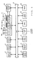
- the digital mixer of the present invention includes a group of electric faders 4 that are provided to adjust signals levels of individual input and output channels on the basis of operation by a user or human operator.
- the group of electric faders 4 are also constructed so that an operating position of any of the electric faders 4 is automatically set in response to an operation command supplied via a bus 12.
- Reference numeral 2 represents a group of switches that includes various switches and LED keys, and the illuminating/deilluminating (OF/OFF) state of an LED built in each of the LED keys is set via the bus 12.
- Group of rotary knobs 6 includes a plurality of rotary knobs for setting left and right sound volume balance of each input/output channel, and the like. Operated amounts of these rotary knobs are output via the bus 12.
- Reference numeral 8 represents a waveform I/O section which inputs/outputs analog or digital audio or sound signals (for convenience, hereinafter referred to as "sound signals"). In the instant embodiment, mixing processing, effect processing, etc. of various sound signals are all carried out in a digital manner.
- both digital sound signals and analog digital signals may be input to the digital mixer from the outside and output from the digital mixer to the outside. Therefore, in the waveform I/O section 8, conversion processes are performed, such as conversion between analog and digital signals and conversion between a plurality of different types of digital signals.
- the waveform I/O section 8 includes a cascade interface section 82, a cascade input terminal 82a for inputting cascade signals from an external mixer, and a cascade output terminal 82b for outputting cascade signals to an external mixer.
- These cascade input and output terminals 82a and 82b are each capable of inputting or outputting digital sound signals of "32" (thirty two) channels (depicted as "MAX32ch” in the figure).
- the waveform I/O section 8 includes two sets of four slots, and up to four input cards and four output cards can be inserted in the two four-slot sets, respectively. Other signals than the cascade signals are input/output via any of these input and output cards.
- the input and output cards and other input and output terminals differ from one another in shape of respective terminals.
- the input and output terminals of the instant embodiment of the digital mixer there are described only the cascade input and output terminals 82a and 82b and input and output cards, for convenience of description; however, the instant embodiment of the digital mixer includes a plurality of other input terminals and a plurality of other output terminals, in addition to the above-mentioned.
- Reference numerals 84-1 - 84-4 represent the four input cards, each of which receives an analog or digital signal from the outside and converts the received analog or digital signal into a digital signal of a predetermined internal format of the digital mixer.
- the input cards 84-1 - 84-4 are of various types, such as a digital sound signal type and analog sound signal type, and the number of input signals to each of the input cards is either "8" or "16" depending on the type of the input card.
- each of the four output cards 86-1 - 86-4 converts a digital signal of the predetermined internal format of the digital mixer into an analog or other-format digital signal.
- the output cards 86-1 - 86-4 are of various types, such as a digital sound signal type and analog sound signal type, and the number of output signals from each of the output cards is either “8” or “16” depending on the type of the output card.
- the digital mixer also includes a signal processing section 10 which is in the form of a group of DSPs (Digital Signal Processors).
- the signal processing section 10 performs mixing processing and effect processing on digital sound signals supplied via the waveform I/O section 8, and it outputs processed results to the waveform I/O section 8.
- 13 represents a backside display section, which is disposed near the cascade input/output terminals 82a and 82b on a backside panel of the digital mixer.
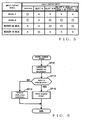
- any one of five different input/output modes as shown in an "Input/Output Mode" section of Fig. 5, can be selected as an operation mode for inputting cascade signals.
- the backside display section 13 includes a set of (five) LEDs corresponding to the "input modes", and a set of (five) LEDs corresponding to the "output modes".
- One of the LEDs in each of the LED sets is selectively illuminated in accordance with the currently-selected input/output mode, while the other LEDs in each of the LED sets are deilluminated. In this way, the user can ascertain or grasp the currently-selected input and output modes, during wiring operation on the backside of the digital mixer, by looking only at the backside panel.
- reference numeral 14 represents a large-size display that is, for example, a flat panel display having a resolution of about "1024 ⁇ 768".
- Input device 15 includes a keyboard and mouse, which is operable by the user to move a cursor on the large-size display 14, turn on/off any of buttons displayed on the large-size display 14 and perform other necessary operation.
- Other I/O section 16 inputs and outputs time codes and other information from and to any of various external devices.
- 18 represents a CPU that controls various components of the digital mixer via the bus 12 on the basis of control programs as will be later described. In an internal program area of a flash memory 20, there are stored the above-mentioned control programs. 22 represents a RAM that is used as a working memory of the CPU 18.
- the input cards 84-1 - 84-4, output cards 86-1 - 86-4, cascade input terminal 82a and cascade output terminal 82b are all implemented by hardware within the waveform I/O section 8 as noted earlier, but the other components than the above-mentioned are implemented by programs running in the signal processing section 10.
- the cascade input terminal 82a is supplied with sound signals of up to "32" channels as noted above, and, in the cascade input terminal 82a, a separate pin is assigned to each of the sound signals. Therefore, for these sound signals, one channel can be uniquely determined by the pin number of each of the pins assigned thereto. Each channel thus determined uniquely by the "pin number” will be referred to as "PIN-specific cascade input channel".
- Sound signals supplied from another mixer via the cascade input terminal 82a are signals corresponding to various buses to be later described (e.g., mixing buses 10, stereo buses 112, 114 and CUE bus 116). Correspondency between these buses and the pin numbers differs among various digital mixer models. Thus, in a case where cascade signals are input to the cascade input terminal 82a from another digital mixer of a model different from the model of the instant embodiment of the digital mixer (hereinafter "model A"), it will be convenient if correspondency between the channel numbers and the various buses is changed in advance to agree with that in model A.
- cascade input physical channel Each channel thus changed, as necessary, in the number by the PIN change section 102 will herein after referred to as "cascade input physical channel".
- one input channel can be uniquely determined in accordance with the "slot number" of the slot having the input card inserted therein and "input terminal number" of the input card.
- Each input channel thus determined by the "slot number” and “input terminal number” will hereinafter be referred to as "normal input physical channel”.
- the four slots in the instant embodiment can secure a maximum of 64 (sixty four) normal input physical channels.
- sound signals of the normal input physical channels are subjected to equalizing processing etc.
- an input signal processing unit (like the one 108 to be later described) and then supplied to a mixing bus group (like the one 110 to be later described) etc., while sound signals of the cascade input physical channels are supplied to the corresponding buses without being subjected to the equalizing processing etc.
- the sound signals of the normal input physical channels can be supplied to the buses as the cascade signals, or the sound signals of the cascade input physical channels, instead of the sound signals of the normal input physical channels, can be supplied to the input signal processing unit 108.
- 104 represents an input logical channel setting section, which switches, as necessary, paths of the sound signals of the normal input physical channels and cascade input physical channels. For each of the signals ultimately supplied to the various buses as the cascade signals after such path switching, one channel can be uniquely determined in correspondence with the bus to which the signal is supplied, and each channel thus determined will hereinafter be referred to as "cascade input logical channel".
- normal input logical channels 64 channels that are to be actually subjected to normal equalizing processing etc. can be assumed in one-to-one relation to the maximum number of the normal input physical channels; these channels will hereinafter be referred to as "normal input logical channels".
- normal input logical channels up to 64 normal input physical channels can be secured, the number of the normal input physical channels decreases when an eight-channel input card is inserted in any of the slots or when no card is inserted in any one of the slots, so that there will occur one or more vacant normal input logical channels.
- a sound signal of any one of the normal input physical channels is used as a sound signal of the cascade input logical channel, there will occur a further vacant normal input logical channel.
- a sound signal of the cascade input physical channel can be assigned to each of such "vacant" normal input logical channels.
- Input mixing channels channels for specifying the sound signals in such processing will hereinafter be referred to as "input mixing channels”.
- Input patch section 106 sets correspondency between the normal input logical channels and the input mixing channels.
- Group of mixing buses 110 comprises "24" (twenty four) monaural mixing buses.
- 112 and 114 represent stereo buses and 116 represents a CUU bus, each of which comprises a pair of left and right buses.
- the input signal processing unit 108 can supply one or more desired buses from among the 30 buses 110 - 116, with sound signals of the individual input mixing channels at desired send levels (i.e., signal delivery levels). Sound signal of each of the cascade input logical input channels, on the other hand, can be supplied to any corresponding one of the buses.
- 118 represents an output signal processing unit 118, which includes output signal processing sections provided in corresponding relation to the 30 buses, performs frequency-characteristic equalizing processing, level adjusting processing, etc. on the sound signals having been mixed via these buses. Because the sound signals input and output to and from the output signal processing unit 118 correspond to the 30 buses 110 - 116, output channels can be set in association with the corresponding buses; these output channels will hereinafter be referred to as "output mixing channels".
- a "PIN-specific cascade output channel” is set for each sound signal output from the cascade output terminal 82b to another digital mixer, using one of pin numbers of the output terminal 82b.
- the pin numbers of the output terminal 82b in the embodiment can be associated with "30" buses 110 - 116 of the other mixer. If the other mixer is of a different model from the instant embodiment, then the relationship between the pin numbers and the buses in the other mixer may differ from that in the case where the other mixer is of model A.
- channels can be set in such a manner as to correspond to the buses (similar to those of the instant embodiment) of the other mixer. Channels set in this manner will hereinafter be referred to as "cascade output physical channels".
- 124 represents a PIN change section, which, as necessary (i.e., in order to match arrangements of the pins in another model), performs a pin number change process on supplied sound signals of the cascade output physical channels and outputs the changed results as sound signals of the PIN-specific cascade output channels.
- channels corresponding to the 30 buses 110 - 116 of the instant embodiment of the mixer can be set for sound signals output from the buses 110 - 116 for cascade connection purposes, and these channels hereinafter be referred to as "cascade output logical channels”.
- an output channel can be uniquely determined, for each of sound signals of a plurality of channels output via the output cards 86-1 - 86-4, in accordance with the "slot number" of the slot having the output card inserted therein and "output terminal number" of the output card.
- Each of such channels hereinafter will be referred to as "normal output physical channels”.
- Sound signals of up to 16 channels (depicted as “MAX16ch” in the figure) can be output via each of the output cards, and four slots are provided in the waveform I/O section 8 for insertion of four output cards, so that a maximum of 64 (sixty four) normal output physical channels can be secured.
- normal output logical channels 120 represents an output patch section that sets correspondency between the normal output logical channels and the output mixing channels.
- sound signals of the normal output logical channels instead of sound signals of the cascade output logical channels, can be output, as sound signals of the cascade output physical channels, via the PIN change section 124 and cascade output terminal 82b.
- sound signals of the cascade output logical channels instead of sound signals of the normal output logical channels, can be output, as sound signals of the normal output physical channels, to the output cards 86-1 - 86-4.
- 122 represents an output logical channel setting section, which switches, as necessary, paths of the sound signals of the normal output physical channels and cascade output logical channels.
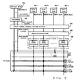
- a setup screen of Fig. 4 is displayed on the large-size display 14.
- 206 represents a CASCADE ON/OFF button that switches between ON/OFF states of the cascade input/output in a toggle-like manner.
- Cascade-input-model selecting box 202 is provided for selecting another mixer ("cascaded-to mixer") from which cascade signals are to be input to the instant embodiment of the digital mixer.
- Cascade-output-model selecting box 210 is provided for selecting another mixer (“cascaded-to mixer") to which cascade signals are to be output from the instant embodiment of the digital mixer.
- Cascade-input-mode selecting box 204 is provided for selecting a "cascade input mode” that specifies a switching state of the input logical channel setting section 104, while a cascade-output-mode selecting box 208 is provided for selecting a "cascade output mode” that specifies a switching state of the output logical channel setting section 122.
- Block diagram display section 212 displays a block diagram for briefly depicting signal flaws in accordance with the cascade input/output mode.
- an "input/output models” section indicates input/output models that can be selected via the cascade-input/output-model selecting boxes 202 and 210.
- Model A is the model of the instant embodiment of the digital mixer as noted earlier
- Model B is the model of another identified digital mixer.
- MIXER32BUS is also an unidentified model where the number of the cascade input/output channels is “32" or less
- MIXER16BUS is an unidentified model where the number of the cascade input/output channels is "16" or less.
- an "input/output mode" of Fig. 5 there are enumerated input/output modes that can be selected by the cascade-input/output-mode selecting boxes 204 and 208.
- a "cascade” mode represents an input/output mode in which the cascade input/output logical channels are assigned directly to the cascade input/output physical channels.
- "SLOT4" mode represents an operation mode in which the normal input/output physical channels corresponding to the fourth input/output slots are assigned to the cascade input/output logical channels and the cascade input/output physical channels are assigned to the normal input/output logical channels corresponding to the fourth input/output slots.
- a "SLOT3/4" mode represents an operation mode in which the normal input/output physical channels corresponding to the third and fourth input/output slots are assigned to the cascade input/output logical channels and the cascade input/output physical channels are assigned to the normal input/output logical channels corresponding to the third and fourth input/output slots.
- a "SLOT1-4[CH1-8]" mode represents an operation mode in which the normal input/output physical channels corresponding to the respective first to eighth channels of the first to fourth input/output slots are assigned to the cascade input/output logical channels and the cascade input/output physical channels are assigned to the normal input/output logical channels corresponding to the first to eighth channels of the first to fourth input/output slots.
- a "SLOT1-4[CH9-16]" mode represents an operation mode in which the normal input/output physical channels corresponding to the respective ninth to sixteenth channels of the first to fourth input/output slots are assigned to the cascade input/output logical channels and the cascade input/output physical channels are assigned to the normal input/output logical channels corresponding to the ninth to sixteenth channels of the first to fourth input/output slots.
- each of rectangular boxes at intersections between the input/output model names and the input/output mode names indicates whether the input/output mode is selectable (" ⁇ ") or not selectable (“ ⁇ ") with the input/output model.
- the "cascade” mode is not selectable with this model. Namely, because "MIXER32BUS” does not indicate any specific model, it is impossible to identify signals (or buses) assigned to the individual cascade input/output physical channels, and thus it is inappropriate to input/output such signals directly to/from the buses 110 - 116. Also, with the"MIXER32BUS” model, the "SLOT4" mode is not selectable either.
- the "MIXER32BUS" model may be safely selected, and thus cascade signals of the "16" channels can be input/output dispersedly via a plurality of the input/output slots.
- any one of the cascade-input/output-model selecting boxes 202 and 210 is clicked via the mouse, a popup window, listing the selectable input/output models, is displayed below the clicked or operated selecting box 202 or 210, so that the user is allowed to newly select an input/output model.
- an input/output model change event routine of Fig. 6 is started up.
- any of the pin numbers is changed via the PIN change section 102 or 124 as necessary.
- "as necessary" means a case when "Model B" has been changed over to another model via the cascade-input/output-model selecting box 202 or 210 or another model has been changed over to "Model B".
- the digital mixer there are prestored data indicative of the correspondency between the buses and pins in each of Model A and Model B, i.e. data indicative of the relationship between the pin numbers of the cascade input/output terminals, namely, which one of the cascade input/output physical channels each of the PIN-specific cascade input/output channels corresponds.
- the PIN change operation at step SP10 is carried out using the prestored data.
- step SP12 a determination is made as to whether there has arisen a need to change the input/output mode, i.e. whether the input/output mode that was being selected prior to the model change is not selectable with the changed model (i.e., newly-selected model).
- a NO determination i.e., selectable with the changed model: " ⁇ "
- the routine goes to step SP14, where the display of the operated cascade-input/output-model selecting box 202 or 210 is changed or updated into contents corresponding to the changed or newly-selected model.
- step SP16 the routine goes to step SP16, where any one of the input/output modes selectable in the model in question is selected compulsorily, so that a mode change event routine of Fig. 7 is started up.
- a popup window listing the selectable input/output modes, is displayed below the clicked or operated selecting box 204 or 208, so that the user is allowed to newly select an input/output mode.
- the input/output mode change event routine of Fig. 7 is started up.
- the input/output mode change event routine is also started up when the above-described operation at step SP16 of Fig. 6 has been executed.
- step SP22 of Fig. 7 a determination is made as to whether the newly-selected input/output mode is the "cascade" mode. With a YES determination, the routine proceeds to step SP24, where the assignment, to the normal input/output logical channels ("NOR. I/O LOGI. CH'S"), of the cascade input/output physical channels ("CAS. I/O PHYSI. CH'S”) is canceled and instead the cascade input/output physical channels (“CAS. I/O PHYSI. CH'S”) are assigned to the cascade input/output logical channels (“CAS. I/O LOGI. CH'S”) via one of the input/output logical channel setting sections 104 and 122.
- next step SP26 the assignment, to the cascade input/output logical channels ("CAS. I/O LOGI. CH'S"), of the normal input/output physical channels ("NOR. I/O PHYSI. CH'S") is canceled and instead the normal input/output physical channels (“NOR. I/O PHYSI. CH'S”) are assigned to the normal input/output logical channels ("NOR. I/O LOGI. CH'S").
- step S22 determines whether the newly-selected input/output mode is a mode other than the "cascade" mode. If, on the other hand, the newly-selected input/output mode is a mode other than the "cascade" mode, a NO determination is made at step S22, so that the routine branches to step SP28.
- step SP28 in accordance with the selected input/output mode, a detection is made of the normal input/output logical channels ("NOR. I/O LOGI. CH'S") to which the cascade input/output physical channels (“CAS. I/O PHYSI. CH'S") should be assigned.
- step SP30 the assignment, to the cascade input/output logical channels ("CAS. I/O LOGI. CH'S"), of the cascade input/output physical channels ("CAS. I/O PHYSI.
- the normal input/output physical channels corresponding to the detected normal input/output logical channels are assigned to the cascade input/output logical channels.
- the normal input/output physical channels corresponding to the other normal input/output logical channels than the normal input/output logical channels detected at step SP28 are assigned to corresponding ones of the normal input/output physical channels (i.e., normal input/output physical channels of the same numbers).
- step SP34 the routine moves on to step SP34, where new input/output setting states of the input/output logical channel setting section 104 or 122 are stored into a predetermined buffer area of the RAM 22.
- step SP36 the displayed contents of the block diagram display section 212 are updated in accordance with the newly-selected input/output mode.
- step SP38 the displayed contents of the backside display section 13 are updated in accordance with the newly-selected input/output mode; that is, the LED corresponding to the newly-selected input/output mode is illuminated, while the LEDs corresponding to the other modes are turned off.
- the block diagram display section 212 includes an input stage display section 212a, and an output stage display section 212b.
- the block diagram display section 212 of Fig. 4 indicates that the "SLOT4" mode has been selected as the input mode and the "SLOT1-4[CH9-16]" mode has been selected as the output mode.
- "SLOT4", "CASCADE IN” and "SLOT1-3" on a left area of the input stage display section 212a each represents "input physical channels”
- “CASCADE IN” and “SLOT IN” on a right area of the input stage display section 212a each represents “input logical channels”.
- Arrows connecting the left and right areas of the input stage display section 212a indicate correspondency between the two areas.
- the input stage display section 212a is set to such displayed contents as illustrated in Fig. 8A, from which it can be seen that the cascade input physical channels correspond to the cascade input logical channels and the normal input physical channels correspond to the normal input logical channels.
- Other displayed contents of the input stage display section 212a when the "SLOT3/4" mode, "SLOT1-4[CH1-8]” mode and “SLOT1-4[CH9-16]” mode have been selected as the input mode are illustrated in Figs. 8B, 8C and 8D, respectively.
- the displayed contents of the output stage display section 212b are set in a similar manner to those of the input stage display section 212a. Namely, in the illustrated example of Fig. 4, "SLOT1-4" and “CASCADE OUT” on a right area of the output stage display section 212b each represents “output physical channels”, while “CASCADE OUT” and “SLOT OUT” on a left area of the output stage display section 212b each represents “output logical channels”. Arrows connecting the left and right areas of the output stage display section 212b indicate correspondency between the two areas.
- the output stage display section 212b is set to such displayed contents as illustrated in Fig.
- FIG. 212 there is displayed an image indicative of outer appearances of the input/output terminals corresponding to the input/output physical channels, adjacent to blocks representing the input/output physical channels.
- reference numerals 214 and 218 represent input slot images that are displayed adjacent to blocks representing the fourth input slot and first to third input slots.
- 216 represents a cascade input terminal image displayed adjacent to the "CASCADE IN" block.
- the output stage display section 212b there are displayed a cascade output terminal image 220 adjacent to the "CASCADE OUT" block, and an output slot image 222 adjacent to blocks representing the first to fourth input slots.
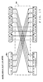
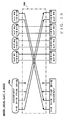
- FIG. 9 shows an example of the connecting relationship when "Model B" has been selected as the input-side connected-to model and the "cascade" mode as the input mode.
- the pin number changing operation is carried out via the PIN change section 102, and the cascade input physical channels are set so that the arrangement of the pins (channel numbers) after the pin number change becomes similar to that of "Model A”.
- the cascade input physical channels and the cascade input logical channels are associated with each other in one-to-one relation
- the normal input physical channels and the normal input logical channels are associated with each other in one-to-one relation
- Fig. 10 shows another example of the connecting relationship when "Model B" has been selected as the input-side connected-to model and the "SLOT1-4[CH1-8]" mode as the input mode.
- the pin number changing operation is carried out in the PIN change section 102.
- the cascade input physical channels after the pin number change are associated with the normal input logical channels corresponding to the respective first to eighth channels of the first to fourth slots, and the normal input logical channels corresponding to the respective first to eighth channels of the first to fourth slots are associated with the 1st to 32nd cascade input logical channels.
- Fig. 11 shows still another example of the connecting relationship when "MIXER32BUS" has been selected as the input-side connected-to model and the "SLOT3/4" mode as the input mode.
- illustration of the PIN change section 102 is omitted in Figs. 11-13 because no pin number change takes place in the change section 102 in the examples of Figs. 11 - 13.
- the 1st to 32nd cascade input physical channels are associated with the normal input logical channels corresponding to the respective 1st to 16th channels of the third and fourth slots
- the normal input physical channels corresponding to the respective 1st to 16th channels of the third and fourth slots are associated with the 1st to 32nd cascade input physical channels.
- the individual normal input physical channels are directly associated with the normal input logical channels.
- Fig. 12 shows still another example of the connecting relationship when "MIXER32BUS" has been selected as the input-side connected-to model and the "SLOT1-4[CH1-8]" mode as the input mode.
- the 1st to 32nd cascade input physical channels are associated with the normal input logical channels corresponding to the respective first to eighth channels of the first to fourth slots
- the normal input physical channels corresponding to the respective first to eighth channels of the first to fourth slots are associated with the 1st to 32nd cascade input logical channels.
- the normal input physical channels corresponding to the respective 9th to 16th of the first to fourth slots are directly associated with the normal input logical channels.
- Fig. 13 shows still another example of the connecting relationship when "MIXER16BUS" has been selected as the input-side connected-to model and the "SLOT4" mode as the input mode.
- the 1st to 16th cascade input physical channels are associated with the normal input logical channels corresponding to the respective 1st to 16th channels of the fourth slot, and the normal input physical channels corresponding to the respective 1st to 16th of the first slot are associated with the 1st to 16th cascade input logical channels.
- the 17th to 32nd cascade input logical channels are "vacant" in this case.
- the normal input physical channels of the first to third slots are directly associated with the normal input logical channels.
- connecting relationship between the input-side PIN change section 102 and the input logical channel setting section 104 has been described above, connecting relationship between the output-side PIN change section 124 and the output logical channel setting section 122 is set in a similar manner to the above-described in accordance with a selected output-side connected-to model and output mode.
- an input patch setting screen of Fig. 14 or output patch setting screen of Fig. 15 is displayed on the large-size display 14.
- Example contents of these screens are described below.
- 302 represents an input category display section that displays a type (category) of means for supplying sound signals of the normal input logical channels to the input patch section 106.
- Portion labeled "SLOT" corresponds to any one of the first to fourth slots.
- ID number display section 304 displays an ID number of the sound signal supply means belonging to the category. Foe example, ID numbers "1" - "4" are assigned to the first to fourth slots, respectively.
- Assignment state display section 308 displays a value "1" when the corresponding normal input logical channel of the identified input means is currently assigned to any one of the input mixing channels, but displays a value "0" when the corresponding normal input logical channel of the identified input means is currently assigned to none of the input mixing channels.
- Channel name display section 320 displays "channel names" assigned to the input mixing channels.
- CHANNEL NAME CHANGE button 318 displays a "channel number" of each of the input mixing channels, and, one this button 318 is clicked via the mouse, a popup window to be used for changing the "channel name” is displayed.
- Assignment state display section 316 displays a value "1" when the corresponding input mixing channel is currently assigned to any one of the normal input logical channels, but displays a value "0" when the input mixing channel is currently assigned to none of the normal input logical channels.
- Grid display section 310 displays a matrix grid by the vertical axis corresponding to the input mixing channels and the horizontal axis corresponding to the normal input logical channels. Each small rectangular block with a " ⁇ " mark therein indicates that the normal input logical channel specified on the horizontal axis is assigned to the input mixing channel specified on the vertical axis.
- the assignment state is changed so that the normal input logical channel is assigned to the input mixing channel corresponding to the clicked block.
- 312 and 314 represent scroll bars for vertically scrolling the grid display section 310.
- 352 represents an output category display section, 354 an ID number display section, 356 a channel number display section and 358 an assignment state display section, which display information of the normal output logical channel in a similar manner to the above-described components 302 - 308 of the input patch setting screen of Fig. 14.
- 370 represents a channel name section and 366 an assignment state display section, which display information of the normal output logical channel in a similar manner to the above-described channel name display section 320 and assignment state display section 316 of the input patch setting screen of Fig. 14.
- 360 represents a grid display section, which displays assignment, to the output mixing channels, of the normal output logical channels.
- 362 and 364 represent scroll bars to be used for vertically scrolling the grid display section 360.
- an input/output-patch-setting-screen request event routine of Fig. 16 is started up.
- the desired one of the patch setting screens of Fig. 14 and Fig. 15 is displayed on the large-size display 14, at which time the grid display section 310 or 360 is displayed in a first display style (e.g., with blue background color).
- step SP52 the input/output settings stored in the RAM 22 (see Fig. 7, step SP34) are read out.
- step SP54 a determination is made as to whether or not the current input/output mode is the "cascade" mode. With a NO determination, the routine goes to step SP56, and a search is made for the normal input/output logical channels currently assigned to the cascade input/output physical channels.
- step SP58 the grid portion of the grid display section 310 or 360, corresponding to the detected normal input/output logical channels, is changed into a second display style.
- the second display style may be implemented here by displaying the background in yellow; however, in the illustrated example of Fig. 14, the second display style is indicated by "hatching". Because, in the illustrated example of Fig. 14, the 9th to 16th channels of the first input slot are indicated in the second display style, the user can ascertain at a glance that the sound signals of such normal input logical channels are actually supplied from the cascade input terminal 82a.
- a grid portion corresponding to "vacant" normal input/output logical channels is changed to a third display style.
- the third display style may be implemented by displaying the background in gray; however, in the illustrated example of Fig. 15, the third display style is indicated by "crosshatchings". Because, in the illustrated example of Fig. 15, the 9th to 16th channels of the first output slot are indicated in the third display style, the user can ascertain at a glance that any sound signal can not be actually outputted from such normal output logical channels.
Landscapes
- Engineering & Computer Science (AREA)
- Signal Processing (AREA)
- Circuit For Audible Band Transducer (AREA)
- Stereophonic System (AREA)
Applications Claiming Priority (6)
| Application Number | Priority Date | Filing Date | Title |
|---|---|---|---|
| JP2004052137A JP4423544B2 (ja) | 2004-02-26 | 2004-02-26 | ミキサおよび音声信号処理方法 |
| JP2004052137 | 2004-02-26 | ||
| JP2004052136 | 2004-02-26 | ||
| JP2004052135 | 2004-02-26 | ||
| JP2004052135A JP4193728B2 (ja) | 2004-02-26 | 2004-02-26 | ミキサ |
| JP2004052136A JP4285271B2 (ja) | 2004-02-26 | 2004-02-26 | ミキサ |
Publications (2)
| Publication Number | Publication Date |
|---|---|
| EP1571768A2 true EP1571768A2 (de) | 2005-09-07 |
| EP1571768A3 EP1571768A3 (de) | 2012-07-18 |
Family
ID=34753504
Family Applications (1)
| Application Number | Title | Priority Date | Filing Date |
|---|---|---|---|
| EP05101302A Withdrawn EP1571768A3 (de) | 2004-02-26 | 2005-02-21 | Mischgerät und Tonsignalverarbeitungsverfahren |
Country Status (3)
| Country | Link |
|---|---|
| US (2) | US7751577B2 (de) |
| EP (1) | EP1571768A3 (de) |
| CN (1) | CN1662101A (de) |
Cited By (3)
| Publication number | Priority date | Publication date | Assignee | Title |
|---|---|---|---|---|
| EP1976160A2 (de) | 2007-03-28 | 2008-10-01 | Yamaha Corporation | Gerät zur Bearbeitung von Mischsignalen und Schaltung mit Bearbeitung von Mischsignalen |
| JP2008242868A (ja) * | 2007-03-28 | 2008-10-09 | Yamaha Corp | 信号処理用集積回路 |
| EP3021504A1 (de) * | 2014-11-17 | 2016-05-18 | Yamaha Corporation | Vorrichtung zur tonsignalverarbeitung |
Families Citing this family (17)
| Publication number | Priority date | Publication date | Assignee | Title |
|---|---|---|---|---|
| EP1571768A3 (de) * | 2004-02-26 | 2012-07-18 | Yamaha Corporation | Mischgerät und Tonsignalverarbeitungsverfahren |
| CN101212845B (zh) * | 2006-12-25 | 2011-05-04 | 上海乐金广电电子有限公司 | 家庭影院系统的扩音器声道的设定方法 |
| TWI475896B (zh) | 2008-09-25 | 2015-03-01 | Dolby Lab Licensing Corp | 單音相容性及揚聲器相容性之立體聲濾波器 |
| JP5246044B2 (ja) * | 2009-05-29 | 2013-07-24 | ヤマハ株式会社 | 音響装置 |
| JP5182226B2 (ja) * | 2009-06-01 | 2013-04-17 | ヤマハ株式会社 | 音響装置 |
| US8526639B2 (en) * | 2009-07-13 | 2013-09-03 | Yamaha Corporation | Digital mixer |
| JP5454405B2 (ja) * | 2010-07-21 | 2014-03-26 | ヤマハ株式会社 | 音響調整卓 |
| JP5682508B2 (ja) * | 2011-08-29 | 2015-03-11 | ヤマハ株式会社 | ミキシングシステム |
| JP5919683B2 (ja) * | 2011-08-29 | 2016-05-18 | ティアック株式会社 | マルチトラックレコーダ装置 |
| CN102984626B (zh) * | 2012-11-22 | 2015-04-01 | 福州瑞芯微电子有限公司 | 一种对音频系统输入数字信号检测校正的方法及装置 |
| EP3796680B1 (de) | 2013-07-22 | 2024-08-28 | Harman Becker Automotive Systems GmbH | Automatische klang- und entzerrungssteuerung |
| EP2830045A1 (de) * | 2013-07-22 | 2015-01-28 | Fraunhofer-Gesellschaft zur Förderung der angewandten Forschung e.V. | Konzept zur Audiocodierung und Audiodecodierung für Audiokanäle und Audioobjekte |
| WO2015010865A1 (en) | 2013-07-22 | 2015-01-29 | Harman Becker Automotive Systems Gmbh | Automatic timbre control |
| US10152030B2 (en) * | 2013-12-31 | 2018-12-11 | Rockwell Automation Technologies, Inc. | Safety relay configuration system with safety monitoring and safety output function blocks |
| US10020151B2 (en) | 2013-12-31 | 2018-07-10 | Rockwell Automation Technologies, Inc. | Safety relay configuration system with multiple test pulse schemes using graphical interface |
| US9977407B2 (en) | 2013-12-31 | 2018-05-22 | Rockwell Automation Technologies, Inc. | Safety relay configuration system for safety mat device using graphical interface |
| JP7039985B2 (ja) * | 2017-12-15 | 2022-03-23 | ヤマハ株式会社 | ミキサ、ミキサの制御方法およびプログラム |
Family Cites Families (15)
| Publication number | Priority date | Publication date | Assignee | Title |
|---|---|---|---|---|
| JPH03148909A (ja) | 1989-11-02 | 1991-06-25 | Yamaha Corp | デジタルオーディオ信号処理装置 |
| WO1993019525A1 (en) * | 1992-03-23 | 1993-09-30 | Euphonix, Inc. | Visual dynamics management for audio instrument |
| JP3221162B2 (ja) * | 1993-06-23 | 2001-10-22 | ヤマハ株式会社 | 遅延補正装置 |
| JPH08195068A (ja) * | 1995-01-20 | 1996-07-30 | Pioneer Electron Corp | オーディオ信号混合装置 |
| AU8698998A (en) * | 1998-01-15 | 1999-08-02 | Mackie Designs Inc. | Digital signal mixing architecture |
| JP2000322057A (ja) * | 1999-05-17 | 2000-11-24 | Teac Corp | 信号混合装置 |
| US7561931B1 (en) * | 2000-08-10 | 2009-07-14 | Ssd Company Limited | Sound processor |
| US7242990B2 (en) * | 2000-12-26 | 2007-07-10 | Yamaha Corporation | Digital mixing system, engine apparatus, console apparatus, digital mixing method, engine apparatus control method, console apparatus control method, and programs executing these control methods |
| JP3700931B2 (ja) * | 2001-06-11 | 2005-09-28 | ヤマハ株式会社 | マルチトラック・ディジタル録音再生装置 |
| US7565212B2 (en) * | 2001-06-13 | 2009-07-21 | Yamaha Corporation | Configuration method of digital audio mixer |
| JP3804824B2 (ja) * | 2001-09-19 | 2006-08-02 | ヤマハ株式会社 | ディジタルミキサ |
| JP4089375B2 (ja) * | 2002-09-30 | 2008-05-28 | ヤマハ株式会社 | ミキシング方法、ミキシング装置およびプログラム |
| JP4062042B2 (ja) * | 2002-10-03 | 2008-03-19 | ヤマハ株式会社 | 信号切換装置 |
| JP4085766B2 (ja) * | 2002-10-04 | 2008-05-14 | ヤマハ株式会社 | ミキシングコンソール |
| EP1571768A3 (de) | 2004-02-26 | 2012-07-18 | Yamaha Corporation | Mischgerät und Tonsignalverarbeitungsverfahren |
-
2005
- 2005-02-21 EP EP05101302A patent/EP1571768A3/de not_active Withdrawn
- 2005-02-24 US US11/067,376 patent/US7751577B2/en not_active Expired - Fee Related
- 2005-02-25 CN CN200510009575.0A patent/CN1662101A/zh active Pending
-
2009
- 2009-05-07 US US12/437,517 patent/US8254599B2/en not_active Expired - Fee Related
Cited By (10)
| Publication number | Priority date | Publication date | Assignee | Title |
|---|---|---|---|---|
| EP1976160A2 (de) | 2007-03-28 | 2008-10-01 | Yamaha Corporation | Gerät zur Bearbeitung von Mischsignalen und Schaltung mit Bearbeitung von Mischsignalen |
| JP2008242868A (ja) * | 2007-03-28 | 2008-10-09 | Yamaha Corp | 信号処理用集積回路 |
| EP1976160A3 (de) * | 2007-03-28 | 2010-02-17 | Yamaha Corporation | Gerät zur Bearbeitung von Mischsignalen und Schaltung mit Bearbeitung von Mischsignalen |
| EP2323289A3 (de) * | 2007-03-28 | 2011-12-07 | Yamaha Corporation | Gerät zur Bearbeitung von Mischsignalen und Schaltung mit Bearbeitung von Mischsignalen |
| US8396578B2 (en) | 2007-03-28 | 2013-03-12 | Yamaha Corporation | Mixing signal processing apparatus and mixing signal processing integrated circuit |
| US8452434B2 (en) | 2007-03-28 | 2013-05-28 | Yamaha Corporation | Mixing signal processing apparatus and mixing signal processing integrated circuit |
| US8467889B2 (en) | 2007-03-28 | 2013-06-18 | Yamaha Corporation | Mixing signal processing apparatus and mixing signal processing integrated circuit |
| US9112622B2 (en) | 2007-03-28 | 2015-08-18 | Yamaha Corporation | Mixing signal processing apparatus and mixing signal processing integrated circuit |
| EP3021504A1 (de) * | 2014-11-17 | 2016-05-18 | Yamaha Corporation | Vorrichtung zur tonsignalverarbeitung |
| US10425755B2 (en) | 2014-11-17 | 2019-09-24 | Yamaha Corporation | Audio signal processing device |
Also Published As
| Publication number | Publication date |
|---|---|
| US7751577B2 (en) | 2010-07-06 |
| US8254599B2 (en) | 2012-08-28 |
| CN1662101A (zh) | 2005-08-31 |
| EP1571768A3 (de) | 2012-07-18 |
| US20090214059A1 (en) | 2009-08-27 |
| US20050190933A1 (en) | 2005-09-01 |
Similar Documents
| Publication | Publication Date | Title |
|---|---|---|
| US8254599B2 (en) | Mixer apparatus and sound signal processing method | |
| US8098850B2 (en) | Digital mixer | |
| US7565212B2 (en) | Configuration method of digital audio mixer | |
| US8351623B2 (en) | Audio mixing apparatus | |
| JP4321259B2 (ja) | ミキサ装置およびミキサ装置の制御方法 | |
| US9570058B2 (en) | Audio signal processing device and parameter adjusting method | |
| US20040015252A1 (en) | Audio signal processing device | |
| US7689307B2 (en) | Digital audio mixer | |
| EP2278735A2 (de) | Digitalmischer | |
| EP3021504A1 (de) | Vorrichtung zur tonsignalverarbeitung | |
| US8392835B2 (en) | Parameter supply apparatus for audio mixing system | |
| JP5182188B2 (ja) | オーディオミキシング装置及びオーディオミキシング用プログラム | |
| US20020107592A1 (en) | Panel search engine for digital sound processing systems | |
| JP4193728B2 (ja) | ミキサ | |
| JP2013243510A (ja) | 制御装置及びプログラム | |
| JP2010232950A (ja) | オーディオミキシング装置及びオーディオミキシング用プログラム | |
| US7395127B2 (en) | Signal processing apparatus with automatic channel naming and numbering | |
| CN111506290B (zh) | 声音信号处理装置、声音信号处理方法及存储有程序的存储介质 | |
| JP4423544B2 (ja) | ミキサおよび音声信号処理方法 | |
| JP4766401B2 (ja) | ミキサ | |
| CN102970650B (zh) | 音频混合系统 | |
| JP4285271B2 (ja) | ミキサ | |
| JP6828594B2 (ja) | 音信号処理装置、音信号処理方法及びプログラム | |
| JP4868023B2 (ja) | ミキサ | |
| US20070064962A1 (en) | Device for setting parameters of mixer |
Legal Events
| Date | Code | Title | Description |
|---|---|---|---|
| PUAI | Public reference made under article 153(3) epc to a published international application that has entered the european phase |
Free format text: ORIGINAL CODE: 0009012 |
|
| 17P | Request for examination filed |
Effective date: 20050225 |
|
| AK | Designated contracting states |
Kind code of ref document: A2 Designated state(s): AT BE BG CH CY CZ DE DK EE ES FI FR GB GR HU IE IS IT LI LT LU MC NL PL PT RO SE SI SK TR |
|
| AX | Request for extension of the european patent |
Extension state: AL BA HR LV MK YU |
|
| RAP1 | Party data changed (applicant data changed or rights of an application transferred) |
Owner name: YAMAHA CORPORATION |
|
| PUAL | Search report despatched |
Free format text: ORIGINAL CODE: 0009013 |
|
| AK | Designated contracting states |
Kind code of ref document: A3 Designated state(s): AT BE BG CH CY CZ DE DK EE ES FI FR GB GR HU IE IS IT LI LT LU MC NL PL PT RO SE SI SK TR |
|
| AX | Request for extension of the european patent |
Extension state: AL BA HR LV MK YU |
|
| AKX | Designation fees paid |
Designated state(s): AT BE BG CH CY CZ DE DK EE ES FI FR GB GR HU IE IS IT LI LT LU MC NL PL PT RO SE SI SK TR |
|
| 17Q | First examination report despatched |
Effective date: 20140717 |
|
| STAA | Information on the status of an ep patent application or granted ep patent |
Free format text: STATUS: THE APPLICATION IS DEEMED TO BE WITHDRAWN |
|
| 18D | Application deemed to be withdrawn |
Effective date: 20141128 |
|
| REG | Reference to a national code |
Ref country code: DE Ref legal event code: R079 Free format text: PREVIOUS MAIN CLASS: H04H0007000000 Ipc: H04H0060000000 |
|
| REG | Reference to a national code |
Ref country code: DE Ref legal event code: R079 Free format text: PREVIOUS MAIN CLASS: H04H0007000000 Ipc: H04H0060000000 Effective date: 20150520 |