EP1571849A2 - Gekrümmte Wavelet-Transformation zur Komprimierung von Bild und Video - Google Patents
Gekrümmte Wavelet-Transformation zur Komprimierung von Bild und Video Download PDFInfo
- Publication number
- EP1571849A2 EP1571849A2 EP05101645A EP05101645A EP1571849A2 EP 1571849 A2 EP1571849 A2 EP 1571849A2 EP 05101645 A EP05101645 A EP 05101645A EP 05101645 A EP05101645 A EP 05101645A EP 1571849 A2 EP1571849 A2 EP 1571849A2
- Authority
- EP
- European Patent Office
- Prior art keywords
- image
- wavelet
- curved
- coefficients
- along
- Prior art date
- Legal status (The legal status is an assumption and is not a legal conclusion. Google has not performed a legal analysis and makes no representation as to the accuracy of the status listed.)
- Withdrawn
Links
- 238000007906 compression Methods 0.000 title abstract description 39
- 230000006835 compression Effects 0.000 title abstract description 39
- 238000013139 quantization Methods 0.000 claims abstract description 25
- 238000000034 method Methods 0.000 claims description 76
- 230000009466 transformation Effects 0.000 claims description 19
- 230000003044 adaptive effect Effects 0.000 claims description 17
- 238000001914 filtration Methods 0.000 claims description 10
- 230000006870 function Effects 0.000 claims description 8
- 238000000844 transformation Methods 0.000 claims description 7
- 230000001131 transforming effect Effects 0.000 claims description 7
- 238000005070 sampling Methods 0.000 claims description 6
- 238000003491 array Methods 0.000 claims description 5
- 230000003247 decreasing effect Effects 0.000 claims description 3
- 230000001419 dependent effect Effects 0.000 claims description 3
- 238000000354 decomposition reaction Methods 0.000 abstract description 21
- 238000012545 processing Methods 0.000 description 33
- 238000010586 diagram Methods 0.000 description 18
- 230000006837 decompression Effects 0.000 description 12
- 230000008901 benefit Effects 0.000 description 5
- 230000008569 process Effects 0.000 description 4
- 230000002123 temporal effect Effects 0.000 description 4
- 238000004891 communication Methods 0.000 description 3
- 238000013144 data compression Methods 0.000 description 3
- 230000008447 perception Effects 0.000 description 3
- 238000013459 approach Methods 0.000 description 2
- 238000012886 linear function Methods 0.000 description 2
- 239000011159 matrix material Substances 0.000 description 2
- 230000000007 visual effect Effects 0.000 description 2
- 230000005540 biological transmission Effects 0.000 description 1
- 238000012512 characterization method Methods 0.000 description 1
- 230000002860 competitive effect Effects 0.000 description 1
- 238000009795 derivation Methods 0.000 description 1
- 238000001514 detection method Methods 0.000 description 1
- 238000009792 diffusion process Methods 0.000 description 1
- 238000003708 edge detection Methods 0.000 description 1
- 238000010191 image analysis Methods 0.000 description 1
- 238000012417 linear regression Methods 0.000 description 1
- 238000005457 optimization Methods 0.000 description 1
- 230000000737 periodic effect Effects 0.000 description 1
- 238000007781 pre-processing Methods 0.000 description 1
- 238000003672 processing method Methods 0.000 description 1
- 238000011160 research Methods 0.000 description 1
- 230000004044 response Effects 0.000 description 1
- 230000035945 sensitivity Effects 0.000 description 1
- 238000000638 solvent extraction Methods 0.000 description 1
- 238000001228 spectrum Methods 0.000 description 1
- 239000013598 vector Substances 0.000 description 1
Images






Classifications
-
- H—ELECTRICITY
- H04—ELECTRIC COMMUNICATION TECHNIQUE
- H04N—PICTORIAL COMMUNICATION, e.g. TELEVISION
- H04N19/00—Methods or arrangements for coding, decoding, compressing or decompressing digital video signals
- H04N19/60—Methods or arrangements for coding, decoding, compressing or decompressing digital video signals using transform coding
- H04N19/63—Methods or arrangements for coding, decoding, compressing or decompressing digital video signals using transform coding using sub-band based transform, e.g. wavelets
-
- H—ELECTRICITY
- H04—ELECTRIC COMMUNICATION TECHNIQUE
- H04N—PICTORIAL COMMUNICATION, e.g. TELEVISION
- H04N19/00—Methods or arrangements for coding, decoding, compressing or decompressing digital video signals
- H04N19/60—Methods or arrangements for coding, decoding, compressing or decompressing digital video signals using transform coding
- H04N19/61—Methods or arrangements for coding, decoding, compressing or decompressing digital video signals using transform coding in combination with predictive coding
-
- H—ELECTRICITY
- H04—ELECTRIC COMMUNICATION TECHNIQUE
- H04N—PICTORIAL COMMUNICATION, e.g. TELEVISION
- H04N19/00—Methods or arrangements for coding, decoding, compressing or decompressing digital video signals
- H04N19/60—Methods or arrangements for coding, decoding, compressing or decompressing digital video signals using transform coding
- H04N19/61—Methods or arrangements for coding, decoding, compressing or decompressing digital video signals using transform coding in combination with predictive coding
- H04N19/619—Methods or arrangements for coding, decoding, compressing or decompressing digital video signals using transform coding in combination with predictive coding the transform being operated outside the prediction loop
-
- H—ELECTRICITY
- H04—ELECTRIC COMMUNICATION TECHNIQUE
- H04N—PICTORIAL COMMUNICATION, e.g. TELEVISION
- H04N19/00—Methods or arrangements for coding, decoding, compressing or decompressing digital video signals
- H04N19/10—Methods or arrangements for coding, decoding, compressing or decompressing digital video signals using adaptive coding
- H04N19/102—Methods or arrangements for coding, decoding, compressing or decompressing digital video signals using adaptive coding characterised by the element, parameter or selection affected or controlled by the adaptive coding
- H04N19/124—Quantisation
-
- H—ELECTRICITY
- H04—ELECTRIC COMMUNICATION TECHNIQUE
- H04N—PICTORIAL COMMUNICATION, e.g. TELEVISION
- H04N19/00—Methods or arrangements for coding, decoding, compressing or decompressing digital video signals
- H04N19/10—Methods or arrangements for coding, decoding, compressing or decompressing digital video signals using adaptive coding
- H04N19/102—Methods or arrangements for coding, decoding, compressing or decompressing digital video signals using adaptive coding characterised by the element, parameter or selection affected or controlled by the adaptive coding
- H04N19/13—Adaptive entropy coding, e.g. adaptive variable length coding [AVLC] or context adaptive binary arithmetic coding [CABAC]
Definitions
- the present invention relates to data processing and more specifically to a method and system for transformation of multi-dimensional images using curved wavelet transforms and recursive wavelet filters for image and video data compression and restoration.
- Image and video compression schemes convert an image consisting of an array of pixels into a sequence of bits. Compression involves transforming the image to a form that can be represented in fewer bits without losing the essential features of the original image. The transformed image is then transmitted over a communication link and the inverse transformation is applied at the receiver to recover the image or a reasonable facsimile thereof.
- Wavelet transform has become a powerful tool for signal processing and image compression.
- a number of image and video compression systems based on wavelet transform and zero-tree coding schemes have been developed.
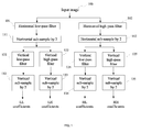
- FIG. 1 schematically shows main steps of this prior-art multi-resolution wavelet transform method at a single resolution level, the steps forming a pyramid or a tree-like structure.
- an input image 100 is transformed in horizontal direction by applying a low-pass wavelet filter in step 101 and a high-pass wavelet filter in a parallel step 102 along rows of the image, producing two images filtered in horizontal directions.
- steps 111 and 112 the two horizontally filtered images are sub-sampled by discarding, respectively, odd and even columns therefrom, resulting in low-pass (L) and high-pass (H) wavelet coefficients images.
- the low-pass and high-pass filters are applied in the vertical direction along the columns of each of the L and H wavelet coefficients images producing four filtered images.
- These four filtered images are down sampled in steps 132-135 in vertical direction by discarding e.g. odd rows in vertically high-pass filtered images, and even rows in vertically low-pass filtered images, producing finally four sub-band images respectively composed ofLL, LH, HL and HH coefficients.
- the process repeats for the LL sub-band image as an input image with wavelet filters at a next resolution level.
- the method is thus recursive and produces a hierarchical sequence of down-sampled low-pass and high-pass filtered images at successively decreasing resolution levels.
- a number of methods have been proposed to code the wavelet coefficients resulting from the multi-level wavelet transform.
- the most important methods include an embedded zero-tree structure (EZW) method disclosed by Shapiro in U. S. Patent 5,315,670, and a set partitioning in hierarchical trees (SPIHT) disclosed by Pearlman et al. in U.S. Patent No. 5,764,807.
- EZW embedded zero-tree structure
- SPIHT set partitioning in hierarchical trees
- These zero-tree structures employ a parent-child relationship between a coefficient at one level of the wavelet transform and four coefficients within a 2 ⁇ 2 square at the next lower level.
- Prior-art wavelet filters used in the wavelet transform are typically finite impulse response (FIR) filters that are implemented with a non-recursive convolution structure, or with a lifting structure.
- FIG. 2 shows a prior-art convolution structure of a symmetric FIR filter with a length of 5.
- FIR filter When a FIR filter is applied to a row, a column of an image, or along a motion trajectory within a video sequence, the sequence of pixels, i.e. image samples, along the row, the column, or the motion trajectory has to be extended in order to result in an output sequence of the same length.
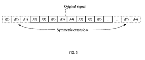
- FIG. 3 illustrates a popularly used prior-art method of symmetric extension, which is often considered to be the best approach in the literature to date.
- wavelet filtering schemes currently used for signal representation are that they do not take advantage of the geometrical regularity of many signal structures. Indeed, these wavelet filters are composed of vectors having a support which is not adapted to the elongation of the signal structures such as regular edges.
- Curvelet bases have recently been introduced in E. Candes and D. Donoho, "Curvelets: A surprisingly effective nonadaptive representation of objects with edges," tech. rep., Stanford Univ., 1999, the contents of which are incorporated in reference herein, to take partial advantage of the geometrical regularity of the signal, by using elongated support zones along different directions. Yet, this strategy has not been able to improve results currently obtained with a wavelet basis on natural images, because it does not incorporate explicitly the geometrical information.
- An edge detector computes an edge map with discretized differential operators and computes some coefficients in order to reconstruct an approximation of the image grey level between edges.
- S. Carlsson "Sketch based coding of gray level images," Signal Processing, Vol. 15, pp. 57-83, July 1988, the contents ofwhich are incorporated by reference herein, an edge detector computes an edge map with discretized derivative operators.
- chain algorithms are used to represent the chains of edge points with as few bits as possible. The left and right pixel values along the edges are kept and an image is reconstructed from these left and right values with a diffusion process.
- U.S. patent No. 6,836,569 issued to Le Pennec and Mallat discloses a processing method and system for n-dimensional signals such as images, wherein foveal filtering and bandelet transforms are used to transform an image taking into account geometrical features therein such as edges.
- foveal processing of the image data is performed to compute foveal coefficients along a set of curved trajectories in the image by using foveal filters with a support across trajectories and along coordinates in the image.
- a second transform is then performed using bandelet filters, or two-dimensional anisotropic wavelets that are warped along a geometric flow in the image.
- This method takes advantage of image content such as regular elongated geometrical structures therein, or edges, but required rather complicated processing using two-dimensional bandelet filters with additional foveal pre-processing.
- a method of image transformation comprising transforming an n-dimensional image, the n-dimensional image representable by an n-dimensional pixel array wherein n ⁇ 2, into a wavelet-transformed image comprised of wavelet coefficients by performing one-dimensional wavelet transforms along a plurality of curved paths dependent upon content of the image, wherein the content of the image includes at least one of: contours within the image, edges within the image, luminance, texture, and color; and wherein the wavelet transformations are performed using wavelet filters having support along the plurality of curved paths, and wherein substantially each pixel is associated with a curved path from the plurality of the curved paths.
- the method of image transformation herein provided comprises decomposing the image into a hierarchical sequence of down-sampled low-pass and high-pass filtered images comprised of wavelet coefficients computed recursively by performing wavelet transforms along pluralities of curved paths at successively decreasing resolution levels.
- a system of image encoding for encoding and compressing images into encoded image data, the image represented using an array of pixels
- the image encoding system comprising: a curve determination unit for determining a plurality of curved paths in an image wherein substantially each pixel is associated with a curved path from the plurality of curved paths; a curved wavelet transform unit for performing wavelet transforms of the image values along the plurality of curved paths and for outputting wavelet transformed images represented by wavelet coefficients; a curve coding unit; a wavelet coefficient quantization unit for performing curved path adaptive quantization of the wavelet coefficients; and, a wavelet coefficient coding unit for performing curved path adaptive coding of the wavelet coefficients.
- a system of image decoding for decoding and restoration of an image encoded by a system employing 1-D wavelet transform along a plurality of curved paths
- the image decoding system comprising: a curve decoding unit for decoding information defining the curved paths; a wavelet coefficient decoding unit responsive to the decoded information defining the curved paths for adaptively decoding wavelet coefficients for the image; a wavelet coefficient de-quantization unit for de-quantization of the decoded wavelet coefficients of the image; and, an inverse curved wavelet transform unit for performing inverse wavelet transformations for restoring image values along the curved paths in the image.
- a method of decompressing an n-dimensional image comprising: receiving image data compressed by a method including the step of transforming the n-dimensional image by multi-level wavelet filtering along curved paths extended by repeating end-point image samples, decoding the image data to obtain sequences of wavelet coefficients along the curved paths, and performing multi-level inverse wavelet transform along the curved paths using recursive wavelet filters.
- FIG. 1 is a block diagram of a prior art wavelet image transform method at a single resolution level.
- FIG. 2 is a diagram of a prior art non-recursive implementation of a symmetric FIR filter.
- FIG. 3 is a diagram of a prior art symmetric extension of a finite length signal for application of the filter shown in FIG. 2.
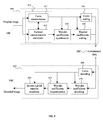
- FIG. 4 is a block diagram of an image compression system using the curved wavelet transform according to the present invention.
- FIG. 5 is a block diagram of the forward curved wavelet transform method of 2-D image transformation at one resolution level according to an embodiment of the present invention.
- FIG. 6a is a diagram showing a first set of curves determined in an input image according to the present invention.
- FIG.6b is a diagram showing low-pass and high-pass images filtered along the first set of curves, and a second and third sets of curves determined therein in accordance with the present invention.
- FIG. 7 is a diagram showing the decomposition of a 3-level curved wavelet transform according to the present invention.
- FIG. 8 is a diagram showing orientations of line segments in one block for vertical curves (a) and horizontal curves (b) according to an exemplary embodiment of the present invention.
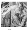
- FIG. 9 is an illustration of curved paths determined in image Barbara according to an embodiment of the present invention.
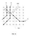
- FIG. 10 is a diagram illustrating an overlapped extension for a curve having an endpoint in the interior of an image.
- FIG. 11 is a diagram of the parent-child relation of the prior art zero-tree structures used in EZW and SPIHT.
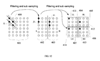
- FIG. 12 is a diagram of establishing the parent-child relations according to the present invention.
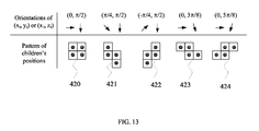
- FIG. 13 is a table of patterns ofthe children's positions for five combinations of curve orientations according to the present invention.
- FIG. 14 is a diagram of the parent-child relation in the adaptive zero-tree structure according to the present invention.
- FIG. 15 is a diagram of an exemplary recursive wavelet filter according to the present invention.
- FIG. 16 is a diagram of signal extension by repeating the boundary samples.
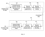
- FIG. 17 is a block diagram of an image compression system using recursive wavelet filters according to the present invention.
- the present invention provides a method of curved wavelet transform (CWT) adaptive to image content, and systems of image and video data compression and decompression using the method.
- the present invention provides also a recursive wavelet filter and a CWT-based image/video compression system using the recursive wavelet filters.
- the curved wavelet transform is carried out by applying one-dimensional (1-D) filters along curved paths in an image, also hereinafter referred to as curves, rather than along only straight lines parallel to coordinate axes in the image, thereby providing a more compact representation of lines and edges in the image.
- the curved paths are determined adaptively to image content, which may include contours within the image, edges within the image, luminance, texture, and color.
- the recursive filters are derived from known, prior-art non-recursive wavelet filters. The wavelet transform using recursive filters require less memory and can also improve image/video quality.
- images are two-dimensional, and are represented by 2-D arrays of pixels arranged in rows and columns, and wherein each pixel has a value also referred to as image value at a particular location.
- the images can be a picture of any kind, a frame of a video, or a residual image obtained from motion compensation of a video.
- n-dimensional signals comprising regular geometrical structures such as edges.
- the method is applicable to video signals wherein time provides a third dimension and which therefore can be considered as 3-D images.
- n-dimensional signals, n ⁇ 2 i.e. signals comprised of symbols organized in an n-dimensional space in an ordered manner, will be referred to as n-dimensional images.
- FIG. 4 A preferred embodiment of an image transformation system using curved wavelet transform (CWT) according to the present invention is shown in FIG. 4 and is hereinafter described.
- CWT curved wavelet transform
- the system is formed by an image compression apparatus 600 and an image decompression apparatus 650.
- the image compression apparatus receives an input, or original image 100, and outputs a compressed data sequence 200.
- the image compression apparatus 600 includes a curve determination unit 611, a forward CWT unit 612, a curve coding unit 620, a wavelet coefficient quantization unit 625, and a wavelet coefficient coding unit 630.
- the curve determination unit 611 adaptively determines a plurality of curves in an original, or input image 100, which are generally oriented parallel to edges and lines present in the input image 100 that is to be transformed.
- the CWT is carried out by applying 1-D wavelet filters along the plurality of curves, rather than along only horizontal and vertical straight lines.
- applying a wavelet filter along a curve means that a support of the wavelet filter coincides with a portion of the curve, and a sequence of image values, or pixels, along the portion of the curve form an input to the wavelet filter. Since a sequence of pixels along a curve that is parallel to lines and edges typically consists mostly of low frequency components, it can be well represented using a smaller number of wavelet coefficients. Therefore, the CWT method of the present invention, which is described in detail hereinbelow, provides a simple and efficient scheme that yields a compact representation of images, improving image and video compression efficiency.
- the quantization and coding ofthe wavelet coefficients performed by units 625 and 630 can be performed adaptively to the curves.
- the decompression apparatus 650 receives the compressed data sequence 200 and outputs a decoded image 100' approximating the input image 100.
- the decompression apparatus 650 includes a curve decoding unit 660, which decodes the curves for each resolution level of the CWT, and provides the information to a wavelet coefficients decoding unit 670, a wavelet coefficients de-quantization unit 675, and an inverse CWT unit 680.
- the inverse CWT unit 680 reconstructs the image 100 by applying inverse wavelet filters along the curves.
- Prior art wavelet-based image compression systems schematically shown in FIG. 1 use the conventional wavelet transform, which is carried out through filtering in the horizontal and vertical directions. These prior-art systems do not therefore require the units of curve determination, curve coding, and curve decoding. The quantization and coding of wavelet coefficients in the prior art systems performed independently on curves in the image and are therefore not adaptive to image content.
- the method of curved wavelet transform is used for multi-level image decomposition in place of the conventional wavelet transform along rows and columns of an image.
- the CWT can be performed jointly with the curve determination, as will be described herein below.
- the curve determination unit 611 and the forward CWT unit 612 together form a common processing block 610.
- FIG. 5 shows a block diagram of a preferred embodiment of the processing block 610 performing the functions of the curve determination unit 611 and the forward CWT unit 612 according to the present invention. Functioning of this block will now be described by describing in general terms the CWT method steps, which the processing block 610 implements according to the present invention.
- the input image 100 which is to be compressed, is sent to a processing unit 700 wherein a first set of curves ⁇ x i ⁇ is determined based on the image 100.
- the curves are generally oriented parallel to the edges and lines in the image, and every pixel of the image 100 is associated with at least one of the curves.
- a processing unit 705 determines image values along every curve x i , and sequences of the image values along every curve x i are extended by the processing unit 710.
- the image processing splits into two branches wherein each sequence of image values along every curve x i is filtered by a low-pass and a high-pass wavelet filter by processing units 715 and 720, respectively.
- the output ofthe low-pass filter is sub-sampled by discarding the columns of odd numbers, resulting in a down-sampled sub-image comprised ofwavelet coefficients hereinafter referred to as L coefficients; whereas that of the high-pass filter is sub-sampled by discarding the columns of even numbers, resulting in a down-sampled sub-image comprised of wavelet coefficients hereinafter referred to as H coefficients.
- L coefficients down-sampled sub-image comprised ofwavelet coefficients
- H coefficients wavelet coefficients
- Coefficient values along every curve y i are then determined by a processing unit 735, and sequences of coefficient values along every curve y i are extended by a processing unit 740. Finally, the sequence of coefficient values along every curve y i is low-pass and high-pass filtered by processing units 745 and 750. An output of the low-pass filter is sub-sampled by discarding rows of odd numbers, resulting in a down-sampled image comprised of LL coefficients of the first level; whereas an output of the high-pass filter is sub-sampled by discarding rows of even numbers, resulting in a down-sampled image comprised ofLH coefficients of the first resolution level.
- the other branch includes processing units 760-780 wherein a third set of curves ⁇ z i ⁇ based on the H coefficients is determined and then the H coefficients are decomposed into HL coefficients and HH coefficients of the first resolution level.
- the process of CWT-based image decomposition described hereinabove is a first level of a multi-level image decomposition.
- An array of the resulting LL coefficients is then considered as an image and is further decomposed using the same process, as illustrated by an arrow 790.
- This recursive decomposition repeats k times.
- the LH, HL, and HH coefficients resulting from all levels of the recursive decomposition and the LL coefficients from the last level are sent to the wavelet coefficients quantization unit 625 and the wavelet coefficients coding unit 630.
- the curves determined at all levels are sent to the curve coding unit 620 shown in FIG. 4.
- Every curve x i in the first set must be a single valued function of, for example, a horizontal coordinate n in the image, x i ( n ). This means that the curve crosses a column of the image only once, if it does.
- the curve can be of any length, but must be continuous without gaps.
- Such a curve is called a horizontal curve in the context of the description herein.
- Image values along the curve come from a set of successive columns of the image, each value coming from a different column. Every pixel in the image to be filtered, or in a corresponding array of coefficients, must be passed by one horizontal curve.
- every curve from the second and third sets must be a continuous, single valued function of the vertical coordinate m , y i ( m ) or z i ( m ), and are therefore referred herein as vertical curves.
- Every L coefficient must be passed by a curve of the second set and every H coefficient must be passed by a curve of the third set.
- the coefficient values along a vertical curve come from a set of successive rows ofthe image, each value coming from a different row.
- curves 520 in an input image 525 belong to the set of horizontal curves ⁇ x i ⁇ , and are contiguous single-valued functions of the horizontal coordinate n.
- Curves 530 in a down-sampled array of low-pass wavelet coefficients 535 belong to the second set ⁇ y i ⁇ of vertical curves, and are continuous, single valued functions of the vertical coordinate m .
- curves 540 in a down-sampled array of high-pass wavelet coefficients 545 belong to the third set ⁇ z i ⁇ of vertical curves, and are continuous, single valued functions of the vertical coordinate m .
- FIG. 7 illustrates a resulting decomposition from a 3-level CWT under these constraints, which is typical for dyadic image decomposition.
- a best set of curves can be determined through rate-distortion optimization.
- One preferred algorithm for determining the curves according to the present invention is to divide the image to be transformed into block of M ⁇ N pixels and to search for the curves that optimize a measure of rate-distortion for each ofthe blocks. With this algorithm, the curves within each block are parallel straight-line segments. A number of allowed orientations and their corresponding angles for the straight-line segments are predefined. The preferred algorithm determines the best of these allowed orientations for each block by performing the following steps:
- a best set of parallel straight lines within a block can be determined by selecting an orientation that minimizes the energy of high-pass wavelet coefficients within the block.
- processing units 705, 735, and 765 determine the image, or coefficient, values along curves. This step is required when a curve passes not exactly through a center of a pixel, but rather between several adjacent pixels; a corresponding position on the curve will be referred hereinafter as a sub-pixel position.
- a simplest method is to use a value of a nearest pixel as the image value at the sub-pixel position.
- a preferred method is to interpolate the image, or coefficient, values at the sub-pixel position, which usually leads to a higher compression capability.
- FIG. 8 illustrates an exemplary embodiment of the curve determination method according to the present invention described in an article "Curved wavelet transform and overlapped extension for image coding", in Proceedings of International Conference on Image Processing 2004, pp. 1273-1276, Singapore, Oct. 24-27, 2004, by Demin Wang, Liang Zhang, and André Vincent, who are the inventors of the present invention, which is incorporated herein by reference.
- the following constraints are imposed on the curves: (i) The image, or an array of wavelet coefficients, to be transformed is divided into square blocks of K ⁇ K pixels; (ii) Within each block, all curves are straight-line segments of the same orientation: for vertical curves x i , the discrete orientations are ⁇ /4, 3 ⁇ /8, ⁇ /2, 5 ⁇ /8, and 3 ⁇ /4; they are shown in FIG.8 by lines 801-805; for horizontal curves y i , the orientations are - ⁇ /4, - ⁇ /8, 0, ⁇ /8, and ⁇ /4, as shown in FIG.8 by lines 806-810. (iii) Sets of curves ⁇ y i ⁇ and ⁇ z i ⁇ are identical.
- Fig. 9 illustrates a set of vertical curves determined using this algorithm for the image Barbara.
- the curves are generally parallel to the edges and lines of orientation between ⁇ /4 and 3 ⁇ /4 in the image.
- the curved wavelet transform can be implemented using either a lifting filter structure or a convolution filter structure. Both structures require that the sequence of image values along each curve be extended.
- processing units 710, 740, and 770 extend the sequence of image, or wavelet coefficient, values along each curve.
- the symmetric extension shown in FIG. 3 can be used for this purpose. However, some of the curves may start and/or end in the interior of the image. Symmetric extension may introduce objectionable artifacts around the endpoints of the curves in the decoded image.
- FIG. 10 A preferred method of curves extension according to the present invention, which will be referred to hereinafter in this specification as overlapped extension, is shown in FIG. 10.
- a curve that has an endpoint in the interior of the image is extended to pixels on other curves, i.e., some image values on other curves are appended to this curve and are used to calculate wavelet coefficients along the curve.
- curve x 3 having an endpoint 251 in the interior of the image is extended with an overlap extension 255 using pixel a on curve x 1 and pixel b on curve x 2 .
- a preferred embodiment ofthe CWT is implemented using lifting filters and the overlapped extension.
- Lifting wavelet filters were described for example in D. S. Taubman and M. W. Marcellin, "JPEG2000: Image Compression Fundamentals, Standards and Practice", Kluwer Academic Publishers, Boston, 2002, page 281 to 289, which is incorporated herein by reference.
- the forward CWT of the values along the curve shown in FIG. 10 x 3 is performed using conventional non-recursive convolutional wavelet filters and the overlapped extension.
- the decompression apparatus 650 if the inverse CWT along the curves x 1 and x 2 shown in FIG. 10 has been done prior to that along the curve x 3 , then the values of pixels a and b are available, and the inverse CWT along the curve x 3 can be performed using the recursive wavelet filters that will be described hereinafter in this specification.
- a curve coding unit 620 is included in the compression apparatus 600, and a curve decoding unit 660 is included in the decompression apparatus 650.
- the curves are represented by their orientation at each pixel, or within each block. They can be coded using entropy coding, run-length coding, or arithmetic coding, as will be clear to those skilled in the art.
- a preferred embodiment of the curve coding has a one-bit header for each set of curves. If all of the curves x i of the first set are horizontal lines or if all of the curves of the second and third sets, ⁇ y i ⁇ and ⁇ z i ⁇ , are vertical lines, the header bit is "0" and the straight lines are not coded. Otherwise, the header is "1" and the orientations of the curves are coded using arithmetic coding.
- the wavelet coefficients quantization unit 625 shown in FIG. 4 can perform a uniform quantization, as used in most prior art wavelet-based image compression systems.
- a preferred quantization method is an adaptive quantization based on human perception and curve orientations.
- the curves are usually parallel to the edges and lines in the image to be compressed.
- the sensitivity of human perception varies with the orientation of the edges and lines.
- human perception is more sensitive to vertical and horizontal lines than to lines of other orientations. Therefore, the step size of the preferred adaptive quantization varies with the orientations of the curves.
- the wavelet coefficients coding 630 in FIG. 4 can be carried out using entropy coding, arithmetic coding, EZW, SPIHT, EBCOT, or their combinations; these coding methods are known to those skilled in the art. After the quantization, a large number of wavelet coefficients become zero.
- the prior art EZW and SPIHT coding methods efficiently organize and represent the quantized wavelet coefficients using a tree structure of the zeros; a detailed description of the EZW method is given e.g. by Shapiro in US Patent 5,315,670 and a detailed description of the SPIHT method is given by Pearlman et al. in U.S. Patent No. 5,764,807, which are incorporated herein by references.
- the tree structure defines a parent-child relationship between the wavelet coefficients at one level and those at the next lower level.
- a parent wavelet coefficient always has four children at the next lower level. In the prior art EZW and SPIHT methods, these four children are always the coefficients within a square of 2x2, as shown in FIG. 11.
- This fixed parent-child relationship is derived from the conventional wavelet transform along the horizontal and vertical directions.
- arrows 270 show parent-child relationship between the coefficients.
- coefficient 260 is a parent of 4 children shown by black circles in a 2x2 square 261.
- each of these 4 children-coefficients from the 2x2 square pattern 261 has 4 children on the next lower level; e.g. coefficient 262 has four children forming a square 2x2 pattern 263.
- the preferred embodiment of the wavelet coefficients coding exploits a zero-tree structure that is adaptive to the curves used in the CWT.
- FIG. 12 schematically shows an image array 401, arrays 402 and 403 ofL and H coefficients resulting from the filtering and sub-sampling along the first set of curves ⁇ x i ⁇ , and 4 arrays 404-407 resulting from the filtering and sub-sampling of the arrays of L and H coefficients 402 and 403 along the second ⁇ y i ⁇ and third ⁇ z i ⁇ sets of curves.
- Orientations of two curves x i that pass through four pixels shown by black circles within a parallelogram 400 are ⁇ /4, that of a curve y i passing through two resulting L coefficients shown as black circles in the array 402 is ⁇ /2, and that of the curves z i passing through two resulting H coefficients is also ⁇ /2.
- Resulting LL, LH, HL, and HH coefficients 411-414 at a next higher level can be considered as obtained from the sub-sampling of the four pixels within the parallelogram 400. Consequently, four children of each of these coefficients 411 - 414 should be within a parallelogram, rather than within a square.
- the adaptive zero-tree positions of the children in an array of coefficients vary depending on the orientations of the curves along which the children are filtered.
- FIG. 13 shows patterns 420, 421, 422, 423, and 424 of the children's positions for five different combinations of curve orientations.
- the children's patterns can be determined similarly, or approximated using one of the patterns shown in FIG. 13.
- two adjacent parents have different children patterns because their corresponding curves are different.
- the two patterns may be overlapped or disconnected.
- at least one ofthe children's patterns of these two parents has to be adjusted in such a way that every child has one and only one parent. This means that a coefficient is coded once and only once. With the adjustment, these two adjacent parents may have three, four, or five children.
- FIG. 14 The parent-child relationship of the adaptive zero-tree structure is illustrated in FIG. 14.
- a parent 430 has 5 children and a parent 431- only 3
- a parent 432 has 4 children arranged in a pattern 422 shown on Fig. 13
- a parent 433 has 4 children arranged in a pattern 420.
- the adaptive zero-trees are represented using several symbols and coded using entropy coding or arithmetic coding.
- a 1-D signal herein is a sequence of samples that can be acquired from any source. It can be a sequence of pixels along a row, a column, or a curve in an image. Also it can be a sequence of pixels from a group of images along the time axis, or along a motion trajectory, for temporal decomposition of video.
- the recursive method described hereinafter in this specification can be extended to the cases of multi-dimensional filters, multi-dimensional signals, and multi-band decomposition, as well as to conventional wavelet decomposition along vertical and horizontal lines.
- the conventional prior art forward and inverse wavelet transforms are performed using four FIR convolution filters or lifting filters.
- an output ofthe low-pass filter is sub-sampled by discarding all samples with odd indices. Remaining output samples are the low-pass wavelet coefficients, or L coefficients in short.
- an output of the high-pass filter is sub-sampled by discarding all samples with even indices, and remaining output samples are the high-pass wavelet coefficients, or H coefficients.
- Ls which is a half-length of the convolution filters
- (i mod 2) is equal to 0, if i is an even number and 1 if i is an odd number.
- F(i) is an L coefficient if i is an even number; otherwise, it is an H coefficient.
- the inverse wavelet transform in conventional image decompression systems is typically carried out by applying a low-pass filter to the L coefficients after up-sampling by 2, applying a high-pass filter to the H coefficients after up-sampling by 2, and adding the two filtered outputs together.
- This process can be equivalently described by equation (2):
- g 0 ( i ) and g 1 ( i ) are also two FIR convolution filters. Lengths of the four filters can be different. To simplify the description herein, short filters are extended to the length ( 2Ls+ 1) of the longest filter by adding zeros.
- the filters described by equations (1) and (2) are implemented using the non-recursive structure of the prior-art convolution filters shown in FIG. 2.
- a recursive wavelet filter 230 for the forward wavelet transform takes previous outputs F ( k ) stored in cells 231 with k ⁇ i, the current input f ( i ) stored in a cell 232, and "future" inputs f ( k ) with k > i stored in cells 233 as the inputs of the filters to calculate the current output F(i). If the signal f ( i ) is sufficiently long, the recursive filters for the forward wavelet transform have the following general form:
- R 0 ( i ) and R 1 ( i ) with -Ls ⁇ i ⁇ Ls are the filter coefficients.
- Ls previously calculated wavelet coefficients and Ls "future" input samples are used as inputs to the forward recursive filter to calculate a "current" wavelet coefficient F ( i ).
- recursive filters for the inverse transform have the following general form:
- Equation (4) Ls previous output samples of the filters and Ls "future" wavelet coefficients are used as inputs to the inverse recursive filter to calculate a current output f ( i ), or a restored image, or pixel value at a current location in the image.
- the coefficients of these recursive filters can be obtained from the FIR convolution filters h 0 ( i ), h 1 ( i ), g 0 ( i ) and g 1 ( i ). For example, given h 0 ( i ) and h 1 ( i ), from (1) we have the following Ls +1 linear equations:
- f ( i ) can be expressed as a linear function of the f ( k ) and F ( k ) on the right side of (6).
- the coefficients of this linear function are r 0 ( i ) when index i is an even number, and r 1 ( i ) when i is an odd number.
- Filter coefficients R 0 ( i ) and R 1 ( i ) in equation (3) can be obtained with a similar method.
- tables 1 and 2 give coefficients for the recursive filters derived from the non-recursive convolution wavelet filters that are popularly used in image analysis and compression, which are described in detail in M. Antonini, et al ., "Image coding using wavelet transform,” IEEE Trans. Image Processing, Vol. 1, pp. 205-220, April 1992., which is incorporated herein by reference.
- the recursive filters defined by equation (4) require Ls+ 1 wavelet coefficients F ( i ) to calculate the current output f ( i ).
- the sequence of wavelet coefficients F ( i ) is defined within the range of 0 ⁇ i ⁇ I and, for i ⁇ 0 and i ⁇ I , the values f ( i ) are available from preceding computation steps. If the integer I is smaller than Ls+ 1, or when index i in equation (4) approaches I and the number of the remaining wavelet coefficients is smaller than Ls+ 1, the recursive filters defined by equation (4) cannot be used directly to calculate f ( i ). In this case, f ( i ) can be obtained using the following recursive filter:
- the filter coefficients r I-i / 0( i ) and r I-i / 1 (i ) can be obtained by a method similar to the aforedescribed method used to obtain r 0 ( i ) and r 1 ( i ) in equation (4).
- An advantage of the recursive wavelet filters is that the wavelet transform implemented with recursive filters requires a small amount of memory and is easy to implement in hardware.
- memory cell 232 for input sample f ( i ) can be overwritten by the output sample F ( i ) as shown by an arrow 234. Therefore, the wavelet transform of an image can be realized using a single image memory.
- a temporal wavelet transform of a group of images can be achieved using only the memory wherein the source images are stored. This significantly simplifies the hardware implementation of the wavelet transform and benefits applications such as digital photography.
- a signal of a finite length to be transformed can be extended by repeating the first and last samples, referred herein as boundary samples, or boundary pixels for images, or by constant padding.
- FIG. 16 illustrates an embodiment of the image transform method of the present invention wherein the left boundary of a sequence 240 of image values f ( i ), referred hereinafter as a signal, along a curve is extended beyond the left boundary by repeating the first sample f (0) to create an extension 243.
- the extended signal comprising sequences 240 and 243 is then forward transformed using conventional non-recursive wavelet filters or lifting filters.
- the boundary image value is reconstructed from first ( Ls+ 1) wavelet coefficients using equation (8), which can be obtained from equation (4) by replacing therein all f ( i ) for i ⁇ 0 by f (0):
- the value f (0) is assigned to all f ( i ) with i ⁇ 0 as illustrated in FIG. 16, and the rest of the image values f ( i ) for i > 0 along the curve can be obtained using the recursive filter defined by equation (4).
- f ( i ) can be perfectly reconstructed from the wavelet coefficients using the recursive wavelet filters.
- all f ( i ) with i ⁇ 0 in equation (4) are replaced by the constant c.
- the aforedescribed method of boundary sample repetition does not introduce new frequency components to the extended signal once used together with the recursive filters of the present invention.
- FIG. 17 shows a block diagram of an image compression system according to an embodiment of the present invention, which employs recursive wavelet filters.
- image here can mean a multi-dimensional signal, including video signal that can be represented as a 3-dimensional image.
- the system shown in FIG. 17 is formed by a compression apparatus 300 and a decompression apparatus 350.
- the compression apparatus 300 includes a forward wavelet transform unit 320 using the aforedescribed boundary pixel repetition for image extension, a wavelet coefficient quantization unit 330, and a wavelet coefficient coding unit 340.
- the decompression apparatus 350 includes a wavelet coefficient decoding unit 360, a wavelet coefficients de-quantization unit 370, and an inverse wavelet transform unit 380 using recursive wavelet filters.
- the transform performed by the forward wavelet transform unit 320 can be the curved wavelet transform, or the conventional wavelet transform.
- the forward wavelet transform unit 320 performs curved wavelet transform and includes a curve determination unit as described hereinabove in this specification in reference to FIG. 4 and 5.
- the transform can be three-dimensional.
- the temporal wavelet transform can be performed along a time axis or along motion trajectories.
- the forward wavelet transform computed in unit 320, is performed with the boundary pixel repetition. Every sequence of pixels to be transformed is first extended by repeating the first pixel of the sequence on the left-hand side, as shown in FIG. 16, and by repeating the last pixel of the sequence on the right-hand side. Similarly to the aforedescribed embodiment of the method and system of the present invention, every extended sequence is then low-pass and high-pass filtered and is sub-sampled by 2, resulting in the L coefficients and the H coefficients, respectively. After a multiple levels of transformation, the resulting hierarchical sequence of wavelet coefficients is sent to the wavelet coefficients quantization unit 330 and the wavelet coefficients coding unit 340.
- the quantized wavelet coefficients can then be coded using entropy coding, arithmetic coding, EZW, SPIHT, EBCOT, or their combinations. Compressed image data with the coded coefficients are sent to the image decompression apparatus 350.
- decoding unit 360 receives the compressed image data and therefrom decodes the wavelets coefficients.
- the curved paths are preferably decoded by the processing unit 360 prior to the decoding of the wavelet coefficients.
- the inverse wavelet transform is performed using the aforedescribed recursive wavelet filters by the processing unit 380, wherein the L and H coefficients resulting from forward filtering along same paths are first interleaved as described hereinbefore in conjunction with equation (1), and every interleaved sequence is then filtered using recursive wavelet filters as described hereinbefore in conjunction with equations (4) - (8), resulting in the coefficients of a lower level or, after all decomposition levels are processed, in the decoded image.
Landscapes
- Engineering & Computer Science (AREA)
- Multimedia (AREA)
- Signal Processing (AREA)
- Compression Or Coding Systems Of Tv Signals (AREA)
- Compression Of Band Width Or Redundancy In Fax (AREA)
Applications Claiming Priority (2)
| Application Number | Priority Date | Filing Date | Title |
|---|---|---|---|
| US54914204P | 2004-03-03 | 2004-03-03 | |
| US549142 | 2004-03-03 |
Publications (2)
| Publication Number | Publication Date |
|---|---|
| EP1571849A2 true EP1571849A2 (de) | 2005-09-07 |
| EP1571849A3 EP1571849A3 (de) | 2008-09-17 |
Family
ID=34911015
Family Applications (1)
| Application Number | Title | Priority Date | Filing Date |
|---|---|---|---|
| EP05101645A Withdrawn EP1571849A3 (de) | 2004-03-03 | 2005-03-03 | Gekrümmte Wavelet-Transformation zur Komprimierung von Bild und Video |
Country Status (3)
| Country | Link |
|---|---|
| US (1) | US7418144B2 (de) |
| EP (1) | EP1571849A3 (de) |
| CA (1) | CA2499163A1 (de) |
Cited By (2)
| Publication number | Priority date | Publication date | Assignee | Title |
|---|---|---|---|---|
| WO2011030304A1 (en) * | 2009-09-09 | 2011-03-17 | Canon Kabushiki Kaisha | Method and device for coding a multi dimensional digital signal |
| CN104581167A (zh) * | 2014-03-07 | 2015-04-29 | 华南理工大学 | 一种用于无线传感网络的分布式图像压缩传输方法 |
Families Citing this family (26)
| Publication number | Priority date | Publication date | Assignee | Title |
|---|---|---|---|---|
| US7937557B2 (en) * | 2004-03-16 | 2011-05-03 | Vns Portfolio Llc | System and method for intercommunication between computers in an array |
| US7565020B2 (en) * | 2004-07-03 | 2009-07-21 | Microsoft Corp. | System and method for image coding employing a hybrid directional prediction and wavelet lifting |
| US7904695B2 (en) | 2006-02-16 | 2011-03-08 | Vns Portfolio Llc | Asynchronous power saving computer |
| US7676096B2 (en) * | 2005-07-08 | 2010-03-09 | Qformx | Modular, low cost, memory efficient, input resolution independent, frame-synchronous, video compression system using multi stage wavelet analysis and temporal signature analysis with a highly optimized hardware implementation |
| US20080212883A1 (en) * | 2005-08-17 | 2008-09-04 | Pixoneer Geomatics, Inc. | Processing Method of Data Structure for Real-Time Image Processing |
| US8000539B2 (en) * | 2005-12-21 | 2011-08-16 | Ntt Docomo, Inc. | Geometrical image representation and compression |
| US7966481B2 (en) | 2006-02-16 | 2011-06-21 | Vns Portfolio Llc | Computer system and method for executing port communications without interrupting the receiving computer |
| US7904615B2 (en) | 2006-02-16 | 2011-03-08 | Vns Portfolio Llc | Asynchronous computer communication |
| US8385671B1 (en) * | 2006-02-24 | 2013-02-26 | Texas Instruments Incorporated | Digital camera and method |
| EP1978449A2 (de) * | 2007-04-06 | 2008-10-08 | Technology Properties Limited | Signalverarbeitung |
| US7831104B2 (en) * | 2007-04-27 | 2010-11-09 | General Electric Company | Using geometric wavelets based on active contours for signal processing |
| US8121435B2 (en) * | 2008-03-31 | 2012-02-21 | Konica Minolta Laboratory U.S.A., Inc. | Systems and methods for resolution switching |
| US20090244601A1 (en) * | 2008-03-31 | 2009-10-01 | Konica Minolta Systems Laboratory, Inc. | Systems and Methods for Color Data Compression |
| US8155436B2 (en) * | 2008-03-31 | 2012-04-10 | Konica Minolta Laboratory U.S.A., Inc. | Systems and methods for color data compression |
| US20120057800A1 (en) * | 2010-09-08 | 2012-03-08 | Guleryuz Onur G | Geometrical image representation and compression |
| CN103718553B (zh) | 2011-08-11 | 2017-03-01 | 太阳专利托管公司 | 图像编码方法、图像解码方法、图像编码装置、图像解码装置及图像编码解码装置 |
| EP4593395A3 (de) * | 2012-10-01 | 2025-10-01 | GE Video Compression, LLC | Skalierbare videocodierung über zwischenschichtvorhersagebeitrag zur erweiterungsschichtvorhersage |
| US9020290B2 (en) * | 2013-01-30 | 2015-04-28 | Microsoft Technology Licensing, Llc | Reduce extrapolate |
| CN104077746B (zh) * | 2013-03-29 | 2017-03-01 | 富士通株式会社 | 灰度图像处理方法及其装置 |
| CN103414901A (zh) * | 2013-08-26 | 2013-11-27 | 江苏新瑞峰信息科技有限公司 | 一种快速jpeg2000图像压缩系统 |
| CN103905831B (zh) * | 2014-04-18 | 2017-01-18 | 西安电子科技大学 | 基于图形处理器的条带波变换图像压缩方法 |
| RU2628122C1 (ru) * | 2015-03-09 | 2017-08-15 | Открытое Акционерное Общество "Пеленг" | Способ аппаратного сжатия цифрового изображения для съемочной аппаратуры сканирующего типа |
| EP3608876A1 (de) * | 2016-09-13 | 2020-02-12 | Dassault Systèmes | Komprimierung eines signals, das ein physikalisches attribut repräsentiert |
| JP7041494B2 (ja) * | 2017-11-06 | 2022-03-24 | キヤノン株式会社 | 画像処理装置および画像処理方法 |
| RU2723896C1 (ru) * | 2018-11-06 | 2020-06-18 | Открытое Акционерное Общество "Пеленг" | Способ эффективного кодирования и декодирования цифрового изображения |
| CN119722712B (zh) * | 2024-12-24 | 2025-09-30 | 广东工业大学 | 一种基于gtf卷积及多频双注意力的肝肿瘤分割方法 |
Family Cites Families (18)
| Publication number | Priority date | Publication date | Assignee | Title |
|---|---|---|---|---|
| US5014134A (en) | 1989-09-11 | 1991-05-07 | Aware, Inc. | Image compression method and apparatus |
| US5048111A (en) | 1989-11-06 | 1991-09-10 | Eastman Kodak Company | Hybrid subband-based hierarchical storage and display method for high resolution digital images in a multiuse environment |
| US5315670A (en) | 1991-11-12 | 1994-05-24 | General Electric Company | Digital data compression system including zerotree coefficient coding |
| AU1727495A (en) | 1994-01-14 | 1995-08-01 | Houston Advanced Research Center | Boundary-spline-wavelet compression for video images |
| JP3764765B2 (ja) | 1995-09-06 | 2006-04-12 | インターナショナル・ビジネス・マシーンズ・コーポレーション | ディジタル画像の処理方法及びシステム |
| US5764807A (en) | 1995-09-14 | 1998-06-09 | Primacomp, Inc. | Data compression using set partitioning in hierarchical trees |
| JP3836145B2 (ja) | 1995-10-18 | 2006-10-18 | コーニンクレッカ フィリップス エレクトロニクス エヌ ヴィ | 領域ベーステクスチュアコード化及びデコード方法、及び対応するシステム |
| JP3213222B2 (ja) | 1995-11-02 | 2001-10-02 | 株式会社リコー | 符号化方法 |
| US5790269A (en) | 1995-12-12 | 1998-08-04 | Massachusetts Institute Of Technology | Method and apparatus for compressing and decompressing a video image |
| US6141452A (en) | 1996-05-13 | 2000-10-31 | Fujitsu Limited | Apparatus for compressing and restoring image data using wavelet transform |
| US5799100A (en) | 1996-06-03 | 1998-08-25 | University Of South Florida | Computer-assisted method and apparatus for analysis of x-ray images using wavelet transforms |
| US6233357B1 (en) | 1997-07-14 | 2001-05-15 | Sharp Laboratories Of America, Inc. | Arbitrary shape wavelet transform with phase alignment |
| US6233358B1 (en) | 1998-07-13 | 2001-05-15 | Intel Corporation | Image compression using directional predictive coding of the wavelet coefficients |
| US6229926B1 (en) | 1998-07-24 | 2001-05-08 | Picsurf, Inc. | Memory saving wavelet-like image transform system and method for digital camera and other memory conservative applications |
| US7421136B2 (en) * | 1999-11-24 | 2008-09-02 | Ge Medical Systems Information Technologies Inc. | Image tessellation for region-specific coefficient access |
| US6549674B1 (en) | 2000-10-12 | 2003-04-15 | Picsurf, Inc. | Image compression based on tiled wavelet-like transform using edge and non-edge filters |
| US6836569B2 (en) * | 2001-04-13 | 2004-12-28 | Erwan Le Pennec | Method and apparatus for processing or compressing n-dimensional signals by foveal filtering along trajectories |
| US20030002582A1 (en) * | 2001-06-13 | 2003-01-02 | Pere Obrador | Multi-resolution boundary encoding applied to region based still image and video encoding |
-
2005
- 2005-03-01 CA CA002499163A patent/CA2499163A1/en not_active Abandoned
- 2005-03-01 US US11/068,160 patent/US7418144B2/en not_active Expired - Fee Related
- 2005-03-03 EP EP05101645A patent/EP1571849A3/de not_active Withdrawn
Non-Patent Citations (9)
| Title |
|---|
| BARNARD H J ET AL: "EFFICIENT SIGNAL EXTENSION FOR SUBBAND/WAVELET DECOMPOSITION OF ARBITRARY LENGTH SIGNALS" PROCEEDINGS OF THE SPIE, SPIE, BELLINGHAM, VA, US, vol. 2094, November 1993 (1993-11), pages 966-975, XP000937947 ISSN: 0277-786X * |
| DEMIN WANG ET AL: "Curved wavelet transform and overlapped extension for image coding" IMAGE PROCESSING, 2004. ICIP '04. 2004 INTERNATIONAL CONFERENCE ON SINGAPORE 24-27 OCT. 2004, PISCATAWAY, NJ, USA,IEEE, 24 October 2004 (2004-10-24), pages 1273-1276, XP010785434 ISBN: 0-7803-8554-3 * |
| JIZHENG XU ET AL: "Three-dimensional embedded subband coding with optimized truncation (3-D ESCOT)" APPLIED AND COMPUTATIONAL HARMONIC ANALYSIS ACADEMIC PRESS USA, vol. 10, no. 3, May 2001 (2001-05), pages 290-315, XP002466488 ISSN: 1063-5203 * |
| LE PENNEC E ET AL: "Geometrical image compression with bandelets" PROCEEDINGS OF THE SPIE - THE INTERNATIONAL SOCIETY FOR OPTICAL ENGINEERING SPIE-INT. SOC. OPT. ENG USA, vol. 5150, no. 1, 2003, pages 1273-1286, XP002466489 ISSN: 0277-786X * |
| REED T R: "The computer engineering handbook - Chapter 28: Digital Video Processing" [Online] 26 December 2001 (2001-12-26), CRC PRESS , USA , XP002491473 ISBN: 978-0-849-30885-7 Retrieved from the Internet: URL:http://www.engnetbase.com/> [retrieved on 2008-08-01] Ÿ28.3, section "Spatial Frequency Response" * |
| SAID A ET AL: "Image compression using the spatial-orientation tree" PROCEEDINGS OF THE INTERNATIONAL SYMPOSIUM ON CIRCUITS AND SYSTEMS. (ISCS). CHICAGO, MAY 3 - 6, 1993; [PROCEEDINGS OF THE INTERNATIONAL SYMPOSIUM ON CIRCUITS AND SYSTEMS. (ISCS)], NEW YORK, IEEE, US, vol. -, 3 May 1993 (1993-05-03), pages 279-282, XP010115157 ISBN: 978-0-7803-1281-4 * |
| VELISAVLJEVIC V ET AL: "Discrete multi-directional wavelet bases" PROCEEDINGS 2003 INTERNATIONAL CONFERENCE ON IMAGE PROCESSING. ICIP-2003. BARCELONA, SPAIN, SEPT. 14 - 17, 2003, INTERNATIONAL CONFERENCE ON IMAGE PROCESSING, NEW YORK, NY : IEEE, US, vol. VOL. 2 OF 3, 14 September 2003 (2003-09-14), pages 1025-1028, XP010670093 ISBN: 0-7803-7750-8 * |
| YAO S ET AL: "Image compression with visual features using wavelets" 19930914; 19930914 - 19930917, 14 September 1993 (1993-09-14), pages 159-162, XP010117940 * |
| YIN-TSUNG HWANG ET AL: "Efficient shape-adaptive zero tree coding scheme and its FPGA implementation for DWT based progressive coding" SIGNAL PROCESSING SYSTEMS, 2003. SIPS 2003. IEEE WORKSHOP ON 27 - 29 AUG. 2003, PISCATAWAY, NJ, USA,IEEE, 27 August 2003 (2003-08-27), pages 357-362, XP010661042 ISBN: 978-0-7803-7795-0 * |
Cited By (4)
| Publication number | Priority date | Publication date | Assignee | Title |
|---|---|---|---|---|
| WO2011030304A1 (en) * | 2009-09-09 | 2011-03-17 | Canon Kabushiki Kaisha | Method and device for coding a multi dimensional digital signal |
| EP2299716A1 (de) * | 2009-09-09 | 2011-03-23 | Canon Kabushiki Kaisha | Verfahren und Vorrichtung zur Codierung eines multidimensionalen digitalen Signals |
| US8989278B2 (en) | 2009-09-09 | 2015-03-24 | Canon Kabushiki Kaisha | Method and device for coding a multi dimensional digital signal comprising original samples to form coded stream |
| CN104581167A (zh) * | 2014-03-07 | 2015-04-29 | 华南理工大学 | 一种用于无线传感网络的分布式图像压缩传输方法 |
Also Published As
| Publication number | Publication date |
|---|---|
| US20050196060A1 (en) | 2005-09-08 |
| CA2499163A1 (en) | 2005-09-03 |
| EP1571849A3 (de) | 2008-09-17 |
| US7418144B2 (en) | 2008-08-26 |
Similar Documents
| Publication | Publication Date | Title |
|---|---|---|
| US7418144B2 (en) | Curved wavelet transform for image and video compression | |
| Ding et al. | Adaptive directional lifting-based wavelet transform for image coding | |
| US6519284B1 (en) | Encoding method for the compression of a video sequence | |
| Jasmi et al. | Comparison of image compression techniques using huffman coding, DWT and fractal algorithm | |
| EP0797356B1 (de) | Bildkodierungsverfahren und Bildkodierer | |
| JP2000506686A (ja) | オーバラップブロック動き補償及びゼロツリーウェーブレット符号化を用いる低ビットレートビデオ符号化器 | |
| CN108810534B (zh) | 物联网下基于方向提升小波及改进spiht的图像压缩方法 | |
| US7242717B2 (en) | Wavelet domain motion compensation system | |
| JPH09261644A (ja) | ウエーブレットビデオ符号化方法 | |
| Ma et al. | A CNN-based image compression scheme compatible with JPEG-2000 | |
| CN100534182C (zh) | 考虑与运动矢量的分量相关的部分来编码视频图像的方法 | |
| WO2007083312A2 (en) | Method and apparatus for a multidimensional discrete multiwavelet transform | |
| Zhang et al. | Seafloor image compression using hybrid wavelets and directional filter banks | |
| JP2000032464A (ja) | 画像圧縮 | |
| Zhang et al. | Directional lifting-based wavelet transform for multiple description image coding with quincunx segmentation | |
| Suruliandi et al. | Empirical evaluation of EZW and other encoding techniques in the wavelet-based image compression domain | |
| KR101246115B1 (ko) | 3차원 웨이블릿 기반 영상 부호화/복호화 방법 및 장치 | |
| JP3899737B2 (ja) | 画像符号化装置及び方法 | |
| Li et al. | Wavelet transform approach to video compression | |
| de Queiroz et al. | Wavelet transforms in a JPEG-like image coder | |
| Cappellari et al. | Lossy to lossless spatially scalable depth map coding with cellular automata | |
| Hoag et al. | Underwater video compression using the wavelet transform | |
| Ahmed | Wavelet-based Image Compression using Support Vector Machine Learning and Encoding Techniques. | |
| Rammohan et al. | An Efficient Image Compression Technique with Dead Zone Quantization Through Wavelet-Based Contourlet Transform with Modified SPIHT Encoding | |
| Rossetti et al. | Improved scanning methods for wavelet coefficients of video signals |
Legal Events
| Date | Code | Title | Description |
|---|---|---|---|
| PUAI | Public reference made under article 153(3) epc to a published international application that has entered the european phase |
Free format text: ORIGINAL CODE: 0009012 |
|
| AK | Designated contracting states |
Kind code of ref document: A2 Designated state(s): AT BE BG CH CY CZ DE DK EE ES FI FR GB GR HU IE IS IT LI LT LU MC NL PL PT RO SE SI SK TR |
|
| AX | Request for extension of the european patent |
Extension state: AL BA HR LV MK YU |
|
| RIC1 | Information provided on ipc code assigned before grant |
Ipc: H04N 7/30 20060101AFI20080131BHEP |
|
| PUAL | Search report despatched |
Free format text: ORIGINAL CODE: 0009013 |
|
| AK | Designated contracting states |
Kind code of ref document: A3 Designated state(s): AT BE BG CH CY CZ DE DK EE ES FI FR GB GR HU IE IS IT LI LT LU MC NL PL PT RO SE SI SK TR |
|
| AX | Request for extension of the european patent |
Extension state: AL BA HR LV MK YU |
|
| 17P | Request for examination filed |
Effective date: 20090312 |
|
| AKX | Designation fees paid |
Designated state(s): DE FR GB |
|
| 17Q | First examination report despatched |
Effective date: 20120309 |
|
| STAA | Information on the status of an ep patent application or granted ep patent |
Free format text: STATUS: THE APPLICATION IS DEEMED TO BE WITHDRAWN |
|
| 18D | Application deemed to be withdrawn |
Effective date: 20120919 |