EP1572285B1 - Implantierbare druckabschwächende vorrichtung - Google Patents
Implantierbare druckabschwächende vorrichtung Download PDFInfo
- Publication number
- EP1572285B1 EP1572285B1 EP03770516.7A EP03770516A EP1572285B1 EP 1572285 B1 EP1572285 B1 EP 1572285B1 EP 03770516 A EP03770516 A EP 03770516A EP 1572285 B1 EP1572285 B1 EP 1572285B1
- Authority
- EP
- European Patent Office
- Prior art keywords
- attenuation device
- bladder
- pressure
- attenuation
- vapor pressure
- Prior art date
- Legal status (The legal status is an assumption and is not a legal conclusion. Google has not performed a legal analysis and makes no representation as to the accuracy of the status listed.)
- Expired - Lifetime
Links
- 239000000463 material Substances 0.000 claims description 61
- 239000012530 fluid Substances 0.000 claims description 37
- 210000002700 urine Anatomy 0.000 claims description 26
- 239000007788 liquid Substances 0.000 claims description 18
- 230000002829 reductive effect Effects 0.000 claims description 15
- 230000035699 permeability Effects 0.000 claims description 13
- 210000000056 organ Anatomy 0.000 claims description 12
- 230000001052 transient effect Effects 0.000 claims description 11
- QYSGYZVSCZSLHT-UHFFFAOYSA-N octafluoropropane Chemical compound FC(F)(F)C(F)(F)C(F)(F)F QYSGYZVSCZSLHT-UHFFFAOYSA-N 0.000 claims description 6
- 229960004065 perflutren Drugs 0.000 claims description 6
- 241001465754 Metazoa Species 0.000 claims description 5
- 210000003484 anatomy Anatomy 0.000 claims description 4
- 230000036760 body temperature Effects 0.000 claims description 4
- 229960004692 perflenapent Drugs 0.000 claims description 4
- 229960004624 perflexane Drugs 0.000 claims description 4
- KAVGMUDTWQVPDF-UHFFFAOYSA-N perflubutane Chemical compound FC(F)(F)C(F)(F)C(F)(F)C(F)(F)F KAVGMUDTWQVPDF-UHFFFAOYSA-N 0.000 claims description 4
- 229950003332 perflubutane Drugs 0.000 claims description 4
- LGUZHRODIJCVOC-UHFFFAOYSA-N perfluoroheptane Chemical compound FC(F)(F)C(F)(F)C(F)(F)C(F)(F)C(F)(F)C(F)(F)C(F)(F)F LGUZHRODIJCVOC-UHFFFAOYSA-N 0.000 claims description 4
- ZJIJAJXFLBMLCK-UHFFFAOYSA-N perfluorohexane Chemical compound FC(F)(F)C(F)(F)C(F)(F)C(F)(F)C(F)(F)C(F)(F)F ZJIJAJXFLBMLCK-UHFFFAOYSA-N 0.000 claims description 4
- NJCBUSHGCBERSK-UHFFFAOYSA-N perfluoropentane Chemical compound FC(F)(F)C(F)(F)C(F)(F)C(F)(F)C(F)(F)F NJCBUSHGCBERSK-UHFFFAOYSA-N 0.000 claims description 4
- 229910018503 SF6 Inorganic materials 0.000 claims description 3
- WMIYKQLTONQJES-UHFFFAOYSA-N hexafluoroethane Chemical compound FC(F)(F)C(F)(F)F WMIYKQLTONQJES-UHFFFAOYSA-N 0.000 claims description 3
- SFZCNBIFKDRMGX-UHFFFAOYSA-N sulfur hexafluoride Chemical compound FS(F)(F)(F)(F)F SFZCNBIFKDRMGX-UHFFFAOYSA-N 0.000 claims description 3
- 229960000909 sulfur hexafluoride Drugs 0.000 claims description 3
- LVGUZGTVOIAKKC-UHFFFAOYSA-N 1,1,1,2-tetrafluoroethane Chemical compound FCC(F)(F)F LVGUZGTVOIAKKC-UHFFFAOYSA-N 0.000 claims description 2
- UKACHOXRXFQJFN-UHFFFAOYSA-N heptafluoropropane Chemical compound FC(F)C(F)(F)C(F)(F)F UKACHOXRXFQJFN-UHFFFAOYSA-N 0.000 claims description 2
- WTWWXOGTJWMJHI-UHFFFAOYSA-N perflubron Chemical compound FC(F)(F)C(F)(F)C(F)(F)C(F)(F)C(F)(F)C(F)(F)C(F)(F)C(F)(F)Br WTWWXOGTJWMJHI-UHFFFAOYSA-N 0.000 claims description 2
- 229960001217 perflubron Drugs 0.000 claims description 2
- 229950011087 perflunafene Drugs 0.000 claims description 2
- UWEYRJFJVCLAGH-IJWZVTFUSA-N perfluorodecalin Chemical compound FC1(F)C(F)(F)C(F)(F)C(F)(F)[C@@]2(F)C(F)(F)C(F)(F)C(F)(F)C(F)(F)[C@@]21F UWEYRJFJVCLAGH-IJWZVTFUSA-N 0.000 claims description 2
- YVBBRRALBYAZBM-UHFFFAOYSA-N perfluorooctane Chemical compound FC(F)(F)C(F)(F)C(F)(F)C(F)(F)C(F)(F)C(F)(F)C(F)(F)C(F)(F)F YVBBRRALBYAZBM-UHFFFAOYSA-N 0.000 claims description 2
- QKENRHXGDUPTEM-UHFFFAOYSA-N perfluorophenanthrene Chemical compound FC1(F)C(F)(F)C(F)(F)C(F)(F)C2(F)C3(F)C(F)(F)C(F)(F)C(F)(F)C(F)(F)C3(F)C(F)(F)C(F)(F)C21F QKENRHXGDUPTEM-UHFFFAOYSA-N 0.000 claims description 2
- 210000003932 urinary bladder Anatomy 0.000 description 234
- 239000007789 gas Substances 0.000 description 74
- 239000003570 air Substances 0.000 description 58
- 239000000376 reactant Substances 0.000 description 56
- 238000000034 method Methods 0.000 description 53
- 238000011049 filling Methods 0.000 description 43
- 230000036724 intravesical pressure Effects 0.000 description 37
- 210000003708 urethra Anatomy 0.000 description 35
- 229910001868 water Inorganic materials 0.000 description 34
- XLYOFNOQVPJJNP-UHFFFAOYSA-N water Substances O XLYOFNOQVPJJNP-UHFFFAOYSA-N 0.000 description 28
- 230000004888 barrier function Effects 0.000 description 24
- KRKNYBCHXYNGOX-UHFFFAOYSA-N citric acid Chemical compound OC(=O)CC(O)(C(O)=O)CC(O)=O KRKNYBCHXYNGOX-UHFFFAOYSA-N 0.000 description 24
- 239000000126 substance Substances 0.000 description 22
- CURLTUGMZLYLDI-UHFFFAOYSA-N Carbon dioxide Chemical compound O=C=O CURLTUGMZLYLDI-UHFFFAOYSA-N 0.000 description 18
- 239000000203 mixture Substances 0.000 description 18
- CDBYLPFSWZWCQE-UHFFFAOYSA-L Sodium Carbonate Chemical compound [Na+].[Na+].[O-]C([O-])=O CDBYLPFSWZWCQE-UHFFFAOYSA-L 0.000 description 16
- 210000003205 muscle Anatomy 0.000 description 16
- 210000001519 tissue Anatomy 0.000 description 16
- 230000006870 function Effects 0.000 description 15
- 238000004519 manufacturing process Methods 0.000 description 15
- 238000011282 treatment Methods 0.000 description 15
- 206010011224 Cough Diseases 0.000 description 14
- 230000008901 benefit Effects 0.000 description 14
- 238000006243 chemical reaction Methods 0.000 description 14
- 238000013461 design Methods 0.000 description 14
- 230000009467 reduction Effects 0.000 description 14
- 230000036961 partial effect Effects 0.000 description 13
- 239000004814 polyurethane Substances 0.000 description 12
- 229920002635 polyurethane Polymers 0.000 description 12
- 239000007787 solid Substances 0.000 description 12
- 208000024891 symptom Diseases 0.000 description 12
- 210000001635 urinary tract Anatomy 0.000 description 12
- MHAJPDPJQMAIIY-UHFFFAOYSA-N Hydrogen peroxide Chemical compound OO MHAJPDPJQMAIIY-UHFFFAOYSA-N 0.000 description 11
- 206010021639 Incontinence Diseases 0.000 description 11
- 230000003187 abdominal effect Effects 0.000 description 11
- 230000008602 contraction Effects 0.000 description 11
- 208000037265 diseases, disorders, signs and symptoms Diseases 0.000 description 11
- 230000000694 effects Effects 0.000 description 11
- -1 polyethylene Polymers 0.000 description 11
- 102000008186 Collagen Human genes 0.000 description 10
- 108010035532 Collagen Proteins 0.000 description 10
- OUUQCZGPVNCOIJ-UHFFFAOYSA-M Superoxide Chemical compound [O-][O] OUUQCZGPVNCOIJ-UHFFFAOYSA-M 0.000 description 10
- 239000003054 catalyst Substances 0.000 description 10
- 230000008859 change Effects 0.000 description 10
- 229920001436 collagen Polymers 0.000 description 10
- 238000001802 infusion Methods 0.000 description 10
- 239000002253 acid Substances 0.000 description 9
- 229910002092 carbon dioxide Inorganic materials 0.000 description 9
- 210000004027 cell Anatomy 0.000 description 9
- 230000006835 compression Effects 0.000 description 9
- 238000007906 compression Methods 0.000 description 9
- 229920001577 copolymer Polymers 0.000 description 9
- 208000035475 disorder Diseases 0.000 description 9
- 208000014674 injury Diseases 0.000 description 9
- 230000036407 pain Effects 0.000 description 9
- 239000000243 solution Substances 0.000 description 9
- 239000001569 carbon dioxide Substances 0.000 description 8
- 239000003814 drug Substances 0.000 description 8
- 210000004379 membrane Anatomy 0.000 description 8
- 239000012528 membrane Substances 0.000 description 8
- 230000004044 response Effects 0.000 description 8
- 238000007789 sealing Methods 0.000 description 8
- 229910000029 sodium carbonate Inorganic materials 0.000 description 8
- 235000017550 sodium carbonate Nutrition 0.000 description 8
- 239000002904 solvent Substances 0.000 description 8
- 230000008733 trauma Effects 0.000 description 8
- 102000004190 Enzymes Human genes 0.000 description 7
- 108090000790 Enzymes Proteins 0.000 description 7
- 238000004891 communication Methods 0.000 description 7
- 238000010276 construction Methods 0.000 description 7
- 238000003780 insertion Methods 0.000 description 7
- 230000037431 insertion Effects 0.000 description 7
- 230000002485 urinary effect Effects 0.000 description 7
- QTBSBXVTEAMEQO-UHFFFAOYSA-N Acetic acid Chemical compound CC(O)=O QTBSBXVTEAMEQO-UHFFFAOYSA-N 0.000 description 6
- 102000016942 Elastin Human genes 0.000 description 6
- 108010014258 Elastin Proteins 0.000 description 6
- UIIMBOGNXHQVGW-UHFFFAOYSA-M Sodium bicarbonate Chemical compound [Na+].OC([O-])=O UIIMBOGNXHQVGW-UHFFFAOYSA-M 0.000 description 6
- HEMHJVSKTPXQMS-UHFFFAOYSA-M Sodium hydroxide Chemical compound [OH-].[Na+] HEMHJVSKTPXQMS-UHFFFAOYSA-M 0.000 description 6
- QVGXLLKOCUKJST-UHFFFAOYSA-N atomic oxygen Chemical compound [O] QVGXLLKOCUKJST-UHFFFAOYSA-N 0.000 description 6
- 230000007423 decrease Effects 0.000 description 6
- 229920002549 elastin Polymers 0.000 description 6
- 239000010408 film Substances 0.000 description 6
- 230000007794 irritation Effects 0.000 description 6
- 239000001301 oxygen Substances 0.000 description 6
- 229910052760 oxygen Inorganic materials 0.000 description 6
- 230000008569 process Effects 0.000 description 6
- 230000003014 reinforcing effect Effects 0.000 description 6
- 230000003068 static effect Effects 0.000 description 6
- 230000035882 stress Effects 0.000 description 6
- 238000012360 testing method Methods 0.000 description 6
- 239000004698 Polyethylene Substances 0.000 description 5
- UIIMBOGNXHQVGW-DEQYMQKBSA-M Sodium bicarbonate-14C Chemical compound [Na+].O[14C]([O-])=O UIIMBOGNXHQVGW-DEQYMQKBSA-M 0.000 description 5
- 206010046479 Urethral valves Diseases 0.000 description 5
- 210000002808 connective tissue Anatomy 0.000 description 5
- 238000006073 displacement reaction Methods 0.000 description 5
- 229940079593 drug Drugs 0.000 description 5
- 210000005248 left atrial appendage Anatomy 0.000 description 5
- 230000014759 maintenance of location Effects 0.000 description 5
- 238000005259 measurement Methods 0.000 description 5
- 230000007246 mechanism Effects 0.000 description 5
- 150000002978 peroxides Chemical class 0.000 description 5
- 230000001225 therapeutic effect Effects 0.000 description 5
- IJGRMHOSHXDMSA-UHFFFAOYSA-N Atomic nitrogen Chemical compound N#N IJGRMHOSHXDMSA-UHFFFAOYSA-N 0.000 description 4
- VTYYLEPIZMXCLO-UHFFFAOYSA-L Calcium carbonate Chemical compound [Ca+2].[O-]C([O-])=O VTYYLEPIZMXCLO-UHFFFAOYSA-L 0.000 description 4
- BVKZGUZCCUSVTD-UHFFFAOYSA-L Carbonate Chemical compound [O-]C([O-])=O BVKZGUZCCUSVTD-UHFFFAOYSA-L 0.000 description 4
- VZCYOOQTPOCHFL-OWOJBTEDSA-N Fumaric acid Chemical compound OC(=O)\C=C\C(O)=O VZCYOOQTPOCHFL-OWOJBTEDSA-N 0.000 description 4
- 208000005615 Interstitial Cystitis Diseases 0.000 description 4
- 241000405070 Percophidae Species 0.000 description 4
- 239000002250 absorbent Substances 0.000 description 4
- 230000002745 absorbent Effects 0.000 description 4
- 230000003416 augmentation Effects 0.000 description 4
- 150000004649 carbonic acid derivatives Chemical class 0.000 description 4
- 230000008878 coupling Effects 0.000 description 4
- 238000010168 coupling process Methods 0.000 description 4
- 238000005859 coupling reaction Methods 0.000 description 4
- 201000003146 cystitis Diseases 0.000 description 4
- 230000006378 damage Effects 0.000 description 4
- 230000004064 dysfunction Effects 0.000 description 4
- 229920001971 elastomer Polymers 0.000 description 4
- 239000000806 elastomer Substances 0.000 description 4
- 239000006260 foam Substances 0.000 description 4
- 238000002513 implantation Methods 0.000 description 4
- JJTUDXZGHPGLLC-UHFFFAOYSA-N lactide Chemical compound CC1OC(=O)C(C)OC1=O JJTUDXZGHPGLLC-UHFFFAOYSA-N 0.000 description 4
- 229920000573 polyethylene Polymers 0.000 description 4
- 229920000642 polymer Polymers 0.000 description 4
- 229920001296 polysiloxane Polymers 0.000 description 4
- 239000000047 product Substances 0.000 description 4
- 238000002560 therapeutic procedure Methods 0.000 description 4
- 239000010409 thin film Substances 0.000 description 4
- 230000000472 traumatic effect Effects 0.000 description 4
- 238000002604 ultrasonography Methods 0.000 description 4
- 238000003466 welding Methods 0.000 description 4
- VPVXHAANQNHFSF-UHFFFAOYSA-N 1,4-dioxan-2-one Chemical compound O=C1COCCO1 VPVXHAANQNHFSF-UHFFFAOYSA-N 0.000 description 3
- RKDVKSZUMVYZHH-UHFFFAOYSA-N 1,4-dioxane-2,5-dione Chemical compound O=C1COC(=O)CO1 RKDVKSZUMVYZHH-UHFFFAOYSA-N 0.000 description 3
- 206010020853 Hypertonic bladder Diseases 0.000 description 3
- MWCLLHOVUTZFKS-UHFFFAOYSA-N Methyl cyanoacrylate Chemical compound COC(=O)C(=C)C#N MWCLLHOVUTZFKS-UHFFFAOYSA-N 0.000 description 3
- 208000009722 Overactive Urinary Bladder Diseases 0.000 description 3
- 229920001328 Polyvinylidene chloride Polymers 0.000 description 3
- 208000005392 Spasm Diseases 0.000 description 3
- 206010066218 Stress Urinary Incontinence Diseases 0.000 description 3
- 206010046555 Urinary retention Diseases 0.000 description 3
- 208000026723 Urinary tract disease Diseases 0.000 description 3
- 208000027418 Wounds and injury Diseases 0.000 description 3
- WFDIJRYMOXRFFG-UHFFFAOYSA-N acetic acid anhydride Natural products CC(=O)OC(C)=O WFDIJRYMOXRFFG-UHFFFAOYSA-N 0.000 description 3
- 230000009471 action Effects 0.000 description 3
- 239000000853 adhesive Substances 0.000 description 3
- 230000001070 adhesive effect Effects 0.000 description 3
- 230000032683 aging Effects 0.000 description 3
- 238000013459 approach Methods 0.000 description 3
- 230000004323 axial length Effects 0.000 description 3
- 238000000576 coating method Methods 0.000 description 3
- 230000001276 controlling effect Effects 0.000 description 3
- 238000000354 decomposition reaction Methods 0.000 description 3
- 210000004177 elastic tissue Anatomy 0.000 description 3
- 210000003811 finger Anatomy 0.000 description 3
- 238000004108 freeze drying Methods 0.000 description 3
- 230000035876 healing Effects 0.000 description 3
- 230000001976 improved effect Effects 0.000 description 3
- 230000006872 improvement Effects 0.000 description 3
- 238000011065 in-situ storage Methods 0.000 description 3
- 208000015181 infectious disease Diseases 0.000 description 3
- 230000004941 influx Effects 0.000 description 3
- 238000007915 intraurethral administration Methods 0.000 description 3
- 230000000670 limiting effect Effects 0.000 description 3
- 210000004072 lung Anatomy 0.000 description 3
- 229910052751 metal Inorganic materials 0.000 description 3
- 239000002184 metal Substances 0.000 description 3
- 238000012986 modification Methods 0.000 description 3
- 230000004048 modification Effects 0.000 description 3
- 210000002161 motor neuron Anatomy 0.000 description 3
- 210000005036 nerve Anatomy 0.000 description 3
- BCCOBQSFUDVTJQ-UHFFFAOYSA-N octafluorocyclobutane Chemical compound FC1(F)C(F)(F)C(F)(F)C1(F)F BCCOBQSFUDVTJQ-UHFFFAOYSA-N 0.000 description 3
- 235000019407 octafluorocyclobutane Nutrition 0.000 description 3
- 208000020629 overactive bladder Diseases 0.000 description 3
- RVTZCBVAJQQJTK-UHFFFAOYSA-N oxygen(2-);zirconium(4+) Chemical compound [O-2].[O-2].[Zr+4] RVTZCBVAJQQJTK-UHFFFAOYSA-N 0.000 description 3
- 210000004197 pelvis Anatomy 0.000 description 3
- 229920003023 plastic Polymers 0.000 description 3
- 239000004033 plastic Substances 0.000 description 3
- 239000005033 polyvinylidene chloride Substances 0.000 description 3
- 210000002307 prostate Anatomy 0.000 description 3
- 230000035939 shock Effects 0.000 description 3
- 230000011664 signaling Effects 0.000 description 3
- 206010041232 sneezing Diseases 0.000 description 3
- 235000017557 sodium bicarbonate Nutrition 0.000 description 3
- 229910000030 sodium bicarbonate Inorganic materials 0.000 description 3
- 208000022170 stress incontinence Diseases 0.000 description 3
- 230000009466 transformation Effects 0.000 description 3
- 208000014001 urinary system disease Diseases 0.000 description 3
- 230000003202 urodynamic effect Effects 0.000 description 3
- 210000005166 vasculature Anatomy 0.000 description 3
- AJDIZQLSFPQPEY-UHFFFAOYSA-N 1,1,2-Trichlorotrifluoroethane Chemical compound FC(F)(Cl)C(F)(Cl)Cl AJDIZQLSFPQPEY-UHFFFAOYSA-N 0.000 description 2
- DDMOUSALMHHKOS-UHFFFAOYSA-N 1,2-dichloro-1,1,2,2-tetrafluoroethane Chemical compound FC(F)(Cl)C(F)(F)Cl DDMOUSALMHHKOS-UHFFFAOYSA-N 0.000 description 2
- RYHBNJHYFVUHQT-UHFFFAOYSA-N 1,4-Dioxane Chemical compound C1COCCO1 RYHBNJHYFVUHQT-UHFFFAOYSA-N 0.000 description 2
- RFCAUADVODFSLZ-UHFFFAOYSA-N 1-Chloro-1,1,2,2,2-pentafluoroethane Chemical compound FC(F)(F)C(F)(F)Cl RFCAUADVODFSLZ-UHFFFAOYSA-N 0.000 description 2
- 241000272525 Anas platyrhynchos Species 0.000 description 2
- 206010004446 Benign prostatic hyperplasia Diseases 0.000 description 2
- BVKZGUZCCUSVTD-UHFFFAOYSA-M Bicarbonate Chemical class OC([O-])=O BVKZGUZCCUSVTD-UHFFFAOYSA-M 0.000 description 2
- 206010069632 Bladder dysfunction Diseases 0.000 description 2
- 206010005052 Bladder irritation Diseases 0.000 description 2
- 201000004569 Blindness Diseases 0.000 description 2
- 0 C*C[C@](C)(*)CN Chemical compound C*C[C@](C)(*)CN 0.000 description 2
- OKTJSMMVPCPJKN-UHFFFAOYSA-N Carbon Chemical compound [C] OKTJSMMVPCPJKN-UHFFFAOYSA-N 0.000 description 2
- 102000016938 Catalase Human genes 0.000 description 2
- 108010053835 Catalase Proteins 0.000 description 2
- MYMOFIZGZYHOMD-UHFFFAOYSA-N Dioxygen Chemical compound O=O MYMOFIZGZYHOMD-UHFFFAOYSA-N 0.000 description 2
- 208000007101 Muscle Cramp Diseases 0.000 description 2
- 208000000693 Neurogenic Urinary Bladder Diseases 0.000 description 2
- 206010029279 Neurogenic bladder Diseases 0.000 description 2
- KDLHZDBZIXYQEI-UHFFFAOYSA-N Palladium Chemical compound [Pd] KDLHZDBZIXYQEI-UHFFFAOYSA-N 0.000 description 2
- 239000004952 Polyamide Substances 0.000 description 2
- 239000004743 Polypropylene Substances 0.000 description 2
- 208000001647 Renal Insufficiency Diseases 0.000 description 2
- 208000006011 Stroke Diseases 0.000 description 2
- FEWJPZIEWOKRBE-UHFFFAOYSA-N Tartaric acid Natural products [H+].[H+].[O-]C(=O)C(O)C(O)C([O-])=O FEWJPZIEWOKRBE-UHFFFAOYSA-N 0.000 description 2
- 206010046543 Urinary incontinence Diseases 0.000 description 2
- 208000002223 abdominal aortic aneurysm Diseases 0.000 description 2
- 238000010521 absorption reaction Methods 0.000 description 2
- 150000007513 acids Chemical class 0.000 description 2
- 230000004075 alteration Effects 0.000 description 2
- 208000007474 aortic aneurysm Diseases 0.000 description 2
- 210000001367 artery Anatomy 0.000 description 2
- 239000012298 atmosphere Substances 0.000 description 2
- 239000000560 biocompatible material Substances 0.000 description 2
- 230000015572 biosynthetic process Effects 0.000 description 2
- 229920001400 block copolymer Polymers 0.000 description 2
- 210000004556 brain Anatomy 0.000 description 2
- RJCQBQGAPKAMLL-UHFFFAOYSA-N bromotrifluoromethane Chemical compound FC(F)(F)Br RJCQBQGAPKAMLL-UHFFFAOYSA-N 0.000 description 2
- IKZZIQXKLWDPCD-UHFFFAOYSA-N but-1-en-2-ol Chemical compound CCC(O)=C IKZZIQXKLWDPCD-UHFFFAOYSA-N 0.000 description 2
- 239000006227 byproduct Substances 0.000 description 2
- 229910000019 calcium carbonate Inorganic materials 0.000 description 2
- 235000010216 calcium carbonate Nutrition 0.000 description 2
- 210000003169 central nervous system Anatomy 0.000 description 2
- 239000007795 chemical reaction product Substances 0.000 description 2
- 239000003795 chemical substances by application Substances 0.000 description 2
- UUAGAQFQZIEFAH-UHFFFAOYSA-N chlorotrifluoroethylene Chemical group FC(F)=C(F)Cl UUAGAQFQZIEFAH-UHFFFAOYSA-N 0.000 description 2
- AFYPFACVUDMOHA-UHFFFAOYSA-N chlorotrifluoromethane Chemical compound FC(F)(F)Cl AFYPFACVUDMOHA-UHFFFAOYSA-N 0.000 description 2
- 239000002131 composite material Substances 0.000 description 2
- 230000001010 compromised effect Effects 0.000 description 2
- 230000003247 decreasing effect Effects 0.000 description 2
- 230000003111 delayed effect Effects 0.000 description 2
- 230000001419 dependent effect Effects 0.000 description 2
- 238000009792 diffusion process Methods 0.000 description 2
- 229910001882 dioxygen Inorganic materials 0.000 description 2
- 201000010099 disease Diseases 0.000 description 2
- 238000004090 dissolution Methods 0.000 description 2
- 230000002526 effect on cardiovascular system Effects 0.000 description 2
- 238000001125 extrusion Methods 0.000 description 2
- 239000000835 fiber Substances 0.000 description 2
- 239000000945 filler Substances 0.000 description 2
- 239000001530 fumaric acid Substances 0.000 description 2
- 210000000232 gallbladder Anatomy 0.000 description 2
- HCDGVLDPFQMKDK-UHFFFAOYSA-N hexafluoropropylene Chemical group FC(F)=C(F)C(F)(F)F HCDGVLDPFQMKDK-UHFFFAOYSA-N 0.000 description 2
- 229920001519 homopolymer Polymers 0.000 description 2
- 238000002347 injection Methods 0.000 description 2
- 239000007924 injection Substances 0.000 description 2
- 238000009434 installation Methods 0.000 description 2
- 230000003993 interaction Effects 0.000 description 2
- 201000006370 kidney failure Diseases 0.000 description 2
- 238000010030 laminating Methods 0.000 description 2
- 230000007774 longterm Effects 0.000 description 2
- 230000001050 lubricating effect Effects 0.000 description 2
- ZLNQQNXFFQJAID-UHFFFAOYSA-L magnesium carbonate Chemical compound [Mg+2].[O-]C([O-])=O ZLNQQNXFFQJAID-UHFFFAOYSA-L 0.000 description 2
- 239000001095 magnesium carbonate Substances 0.000 description 2
- 229910000021 magnesium carbonate Inorganic materials 0.000 description 2
- 235000014380 magnesium carbonate Nutrition 0.000 description 2
- 238000007726 management method Methods 0.000 description 2
- 229910000000 metal hydroxide Inorganic materials 0.000 description 2
- 150000004692 metal hydroxides Chemical class 0.000 description 2
- 244000005700 microbiome Species 0.000 description 2
- 238000000465 moulding Methods 0.000 description 2
- 210000004877 mucosa Anatomy 0.000 description 2
- 208000010125 myocardial infarction Diseases 0.000 description 2
- 229910052757 nitrogen Inorganic materials 0.000 description 2
- 229940126701 oral medication Drugs 0.000 description 2
- 230000000399 orthopedic effect Effects 0.000 description 2
- 230000008855 peristalsis Effects 0.000 description 2
- 239000012466 permeate Substances 0.000 description 2
- BASFCYQUMIYNBI-UHFFFAOYSA-N platinum Chemical compound [Pt] BASFCYQUMIYNBI-UHFFFAOYSA-N 0.000 description 2
- 229920002647 polyamide Polymers 0.000 description 2
- 229920001155 polypropylene Polymers 0.000 description 2
- BWHMMNNQKKPAPP-UHFFFAOYSA-L potassium carbonate Chemical compound [K+].[K+].[O-]C([O-])=O BWHMMNNQKKPAPP-UHFFFAOYSA-L 0.000 description 2
- 239000012286 potassium permanganate Substances 0.000 description 2
- XXQBEVHPUKOQEO-UHFFFAOYSA-N potassium superoxide Chemical compound [K+].[K+].[O-][O-] XXQBEVHPUKOQEO-UHFFFAOYSA-N 0.000 description 2
- 238000011472 radical prostatectomy Methods 0.000 description 2
- 230000008929 regeneration Effects 0.000 description 2
- 238000011069 regeneration method Methods 0.000 description 2
- 230000001105 regulatory effect Effects 0.000 description 2
- 239000012858 resilient material Substances 0.000 description 2
- 230000002441 reversible effect Effects 0.000 description 2
- 238000005096 rolling process Methods 0.000 description 2
- 150000003839 salts Chemical class 0.000 description 2
- 230000035807 sensation Effects 0.000 description 2
- WBHQBSYUUJJSRZ-UHFFFAOYSA-M sodium bisulfate Chemical compound [Na+].OS([O-])(=O)=O WBHQBSYUUJJSRZ-UHFFFAOYSA-M 0.000 description 2
- 229910000342 sodium bisulfate Inorganic materials 0.000 description 2
- 210000005070 sphincter Anatomy 0.000 description 2
- 229910001220 stainless steel Inorganic materials 0.000 description 2
- 239000010935 stainless steel Substances 0.000 description 2
- 230000000638 stimulation Effects 0.000 description 2
- 238000003860 storage Methods 0.000 description 2
- 238000001356 surgical procedure Methods 0.000 description 2
- 230000001360 synchronised effect Effects 0.000 description 2
- 239000011975 tartaric acid Substances 0.000 description 2
- 235000002906 tartaric acid Nutrition 0.000 description 2
- TXEYQDLBPFQVAA-UHFFFAOYSA-N tetrafluoromethane Chemical compound FC(F)(F)F TXEYQDLBPFQVAA-UHFFFAOYSA-N 0.000 description 2
- 210000003813 thumb Anatomy 0.000 description 2
- 230000000451 tissue damage Effects 0.000 description 2
- 231100000827 tissue damage Toxicity 0.000 description 2
- VZCYOOQTPOCHFL-UHFFFAOYSA-N trans-butenedioic acid Natural products OC(=O)C=CC(O)=O VZCYOOQTPOCHFL-UHFFFAOYSA-N 0.000 description 2
- 238000012546 transfer Methods 0.000 description 2
- 208000019206 urinary tract infection Diseases 0.000 description 2
- 238000012800 visualization Methods 0.000 description 2
- 239000011800 void material Substances 0.000 description 2
- MECDPURMXIJTJZ-UHFFFAOYSA-N 1,1,1,2,2,2-hexafluoroethane;hexafluoro-$l^{6}-sulfane Chemical compound FS(F)(F)(F)(F)F.FC(F)(F)C(F)(F)F MECDPURMXIJTJZ-UHFFFAOYSA-N 0.000 description 1
- LCSKNASZPVZHEG-UHFFFAOYSA-N 3,6-dimethyl-1,4-dioxane-2,5-dione;1,4-dioxane-2,5-dione Chemical compound O=C1COC(=O)CO1.CC1OC(=O)C(C)OC1=O LCSKNASZPVZHEG-UHFFFAOYSA-N 0.000 description 1
- 206010000060 Abdominal distension Diseases 0.000 description 1
- ATRRKUHOCOJYRX-UHFFFAOYSA-N Ammonium bicarbonate Chemical compound [NH4+].OC([O-])=O ATRRKUHOCOJYRX-UHFFFAOYSA-N 0.000 description 1
- 206010002329 Aneurysm Diseases 0.000 description 1
- 201000002862 Angle-Closure Glaucoma Diseases 0.000 description 1
- 241000894006 Bacteria Species 0.000 description 1
- 206010048962 Brain oedema Diseases 0.000 description 1
- PXQNNPDJKSQSMG-UHFFFAOYSA-I C(CC(O)(C(=O)O)CC(=O)O)(=O)O.C([O-])([O-])=O.[Mg+2].C(C)(=O)O.C([O-])([O-])=O.[Ca+2].C(CC(O)(C(=O)O)CC(=O)O)(=O)O.C([O-])(O)=O.[Na+] Chemical compound C(CC(O)(C(=O)O)CC(=O)O)(=O)O.C([O-])([O-])=O.[Mg+2].C(C)(=O)O.C([O-])([O-])=O.[Ca+2].C(CC(O)(C(=O)O)CC(=O)O)(=O)O.C([O-])(O)=O.[Na+] PXQNNPDJKSQSMG-UHFFFAOYSA-I 0.000 description 1
- OYPRJOBELJOOCE-UHFFFAOYSA-N Calcium Chemical compound [Ca] OYPRJOBELJOOCE-UHFFFAOYSA-N 0.000 description 1
- 239000004343 Calcium peroxide Substances 0.000 description 1
- 208000032170 Congenital Abnormalities Diseases 0.000 description 1
- 206010010356 Congenital anomaly Diseases 0.000 description 1
- 206010010774 Constipation Diseases 0.000 description 1
- 229920004937 Dexon® Polymers 0.000 description 1
- FEWJPZIEWOKRBE-JCYAYHJZSA-N Dextrotartaric acid Chemical compound OC(=O)[C@H](O)[C@@H](O)C(O)=O FEWJPZIEWOKRBE-JCYAYHJZSA-N 0.000 description 1
- 206010014561 Emphysema Diseases 0.000 description 1
- VGGSQFUCUMXWEO-UHFFFAOYSA-N Ethene Chemical compound C=C VGGSQFUCUMXWEO-UHFFFAOYSA-N 0.000 description 1
- 239000005977 Ethylene Substances 0.000 description 1
- 229920000219 Ethylene vinyl alcohol Polymers 0.000 description 1
- IWDQPCIQCXRBQP-UHFFFAOYSA-M Fenaminosulf Chemical compound [Na+].CN(C)C1=CC=C(N=NS([O-])(=O)=O)C=C1 IWDQPCIQCXRBQP-UHFFFAOYSA-M 0.000 description 1
- 229910001200 Ferrotitanium Inorganic materials 0.000 description 1
- 206010019196 Head injury Diseases 0.000 description 1
- 206010020772 Hypertension Diseases 0.000 description 1
- SPAGIJMPHSUYSE-UHFFFAOYSA-N Magnesium peroxide Chemical compound [Mg+2].[O-][O-] SPAGIJMPHSUYSE-UHFFFAOYSA-N 0.000 description 1
- 208000012902 Nervous system disease Diseases 0.000 description 1
- 208000025966 Neurological disease Diseases 0.000 description 1
- 239000004341 Octafluorocyclobutane Substances 0.000 description 1
- 239000005062 Polybutadiene Substances 0.000 description 1
- 229920002614 Polyether block amide Polymers 0.000 description 1
- 229920000954 Polyglycolide Polymers 0.000 description 1
- 239000004793 Polystyrene Substances 0.000 description 1
- 208000004403 Prostatic Hyperplasia Diseases 0.000 description 1
- XUIMIQQOPSSXEZ-UHFFFAOYSA-N Silicon Chemical compound [Si] XUIMIQQOPSSXEZ-UHFFFAOYSA-N 0.000 description 1
- BQCADISMDOOEFD-UHFFFAOYSA-N Silver Chemical compound [Ag] BQCADISMDOOEFD-UHFFFAOYSA-N 0.000 description 1
- FAPWRFPIFSIZLT-UHFFFAOYSA-M Sodium chloride Chemical compound [Na+].[Cl-] FAPWRFPIFSIZLT-UHFFFAOYSA-M 0.000 description 1
- RTAQQCXQSZGOHL-UHFFFAOYSA-N Titanium Chemical compound [Ti] RTAQQCXQSZGOHL-UHFFFAOYSA-N 0.000 description 1
- 208000000921 Urge Urinary Incontinence Diseases 0.000 description 1
- 229910021536 Zeolite Inorganic materials 0.000 description 1
- 210000001015 abdomen Anatomy 0.000 description 1
- 210000000683 abdominal cavity Anatomy 0.000 description 1
- 210000003489 abdominal muscle Anatomy 0.000 description 1
- 230000005856 abnormality Effects 0.000 description 1
- 230000001133 acceleration Effects 0.000 description 1
- 150000008065 acid anhydrides Chemical class 0.000 description 1
- 201000001326 acute closed-angle glaucoma Diseases 0.000 description 1
- 230000001154 acute effect Effects 0.000 description 1
- 230000006978 adaptation Effects 0.000 description 1
- 238000004026 adhesive bonding Methods 0.000 description 1
- 230000002411 adverse Effects 0.000 description 1
- PNEYBMLMFCGWSK-UHFFFAOYSA-N aluminium oxide Inorganic materials [O-2].[O-2].[O-2].[Al+3].[Al+3] PNEYBMLMFCGWSK-UHFFFAOYSA-N 0.000 description 1
- 239000001099 ammonium carbonate Substances 0.000 description 1
- 235000012501 ammonium carbonate Nutrition 0.000 description 1
- 238000004873 anchoring Methods 0.000 description 1
- 238000002399 angioplasty Methods 0.000 description 1
- 230000000845 anti-microbial effect Effects 0.000 description 1
- 239000007864 aqueous solution Substances 0.000 description 1
- 230000004872 arterial blood pressure Effects 0.000 description 1
- 208000006673 asthma Diseases 0.000 description 1
- 230000003190 augmentative effect Effects 0.000 description 1
- 238000010009 beating Methods 0.000 description 1
- 230000009286 beneficial effect Effects 0.000 description 1
- 230000005540 biological transmission Effects 0.000 description 1
- 230000007698 birth defect Effects 0.000 description 1
- 210000005068 bladder tissue Anatomy 0.000 description 1
- 230000017531 blood circulation Effects 0.000 description 1
- 238000009530 blood pressure measurement Methods 0.000 description 1
- 210000000988 bone and bone Anatomy 0.000 description 1
- 208000006752 brain edema Diseases 0.000 description 1
- 229910052792 caesium Inorganic materials 0.000 description 1
- TVFDJXOCXUVLDH-UHFFFAOYSA-N caesium atom Chemical compound [Cs] TVFDJXOCXUVLDH-UHFFFAOYSA-N 0.000 description 1
- 239000011575 calcium Substances 0.000 description 1
- 229910052791 calcium Inorganic materials 0.000 description 1
- FUFJGUQYACFECW-UHFFFAOYSA-L calcium hydrogenphosphate Chemical compound [Ca+2].OP([O-])([O-])=O FUFJGUQYACFECW-UHFFFAOYSA-L 0.000 description 1
- LHJQIRIGXXHNLA-UHFFFAOYSA-N calcium peroxide Chemical compound [Ca+2].[O-][O-] LHJQIRIGXXHNLA-UHFFFAOYSA-N 0.000 description 1
- 235000019402 calcium peroxide Nutrition 0.000 description 1
- BVKZGUZCCUSVTD-UHFFFAOYSA-N carbonic acid Chemical class OC(O)=O BVKZGUZCCUSVTD-UHFFFAOYSA-N 0.000 description 1
- 238000005266 casting Methods 0.000 description 1
- 239000013626 chemical specie Substances 0.000 description 1
- 230000035606 childbirth Effects 0.000 description 1
- 235000019406 chloropentafluoroethane Nutrition 0.000 description 1
- 230000001684 chronic effect Effects 0.000 description 1
- 230000007012 clinical effect Effects 0.000 description 1
- 239000011248 coating agent Substances 0.000 description 1
- 210000001072 colon Anatomy 0.000 description 1
- 150000001875 compounds Chemical class 0.000 description 1
- 239000000470 constituent Substances 0.000 description 1
- 239000004035 construction material Substances 0.000 description 1
- 238000007796 conventional method Methods 0.000 description 1
- 230000000593 degrading effect Effects 0.000 description 1
- 230000008021 deposition Effects 0.000 description 1
- 230000006866 deterioration Effects 0.000 description 1
- 230000001627 detrimental effect Effects 0.000 description 1
- 238000003745 diagnosis Methods 0.000 description 1
- 210000000188 diaphragm Anatomy 0.000 description 1
- 230000035487 diastolic blood pressure Effects 0.000 description 1
- HNPSIPDUKPIQMN-UHFFFAOYSA-N dioxosilane;oxo(oxoalumanyloxy)alumane Chemical compound O=[Si]=O.O=[Al]O[Al]=O HNPSIPDUKPIQMN-UHFFFAOYSA-N 0.000 description 1
- 239000006185 dispersion Substances 0.000 description 1
- 238000009826 distribution Methods 0.000 description 1
- 235000012489 doughnuts Nutrition 0.000 description 1
- 238000012377 drug delivery Methods 0.000 description 1
- 238000002651 drug therapy Methods 0.000 description 1
- 206010013781 dry mouth Diseases 0.000 description 1
- 238000001035 drying Methods 0.000 description 1
- 210000005069 ears Anatomy 0.000 description 1
- 239000013013 elastic material Substances 0.000 description 1
- 239000013536 elastomeric material Substances 0.000 description 1
- 238000005516 engineering process Methods 0.000 description 1
- 210000003238 esophagus Anatomy 0.000 description 1
- UFRKOOWSQGXVKV-UHFFFAOYSA-N ethene;ethenol Chemical compound C=C.OC=C UFRKOOWSQGXVKV-UHFFFAOYSA-N 0.000 description 1
- 239000005038 ethylene vinyl acetate Substances 0.000 description 1
- 239000004715 ethylene vinyl alcohol Substances 0.000 description 1
- 238000011156 evaluation Methods 0.000 description 1
- 238000001704 evaporation Methods 0.000 description 1
- 238000000605 extraction Methods 0.000 description 1
- 238000007667 floating Methods 0.000 description 1
- NBVXSUQYWXRMNV-UHFFFAOYSA-N fluoromethane Chemical compound FC NBVXSUQYWXRMNV-UHFFFAOYSA-N 0.000 description 1
- 229920002313 fluoropolymer Polymers 0.000 description 1
- 239000004811 fluoropolymer Substances 0.000 description 1
- 230000004907 flux Effects 0.000 description 1
- 238000009472 formulation Methods 0.000 description 1
- 238000007710 freezing Methods 0.000 description 1
- 230000008014 freezing Effects 0.000 description 1
- 230000002496 gastric effect Effects 0.000 description 1
- 210000001035 gastrointestinal tract Anatomy 0.000 description 1
- 239000011521 glass Substances 0.000 description 1
- 150000004676 glycans Chemical class 0.000 description 1
- 229920000578 graft copolymer Polymers 0.000 description 1
- 230000005484 gravity Effects 0.000 description 1
- 238000009499 grossing Methods 0.000 description 1
- 231100001261 hazardous Toxicity 0.000 description 1
- 238000010438 heat treatment Methods 0.000 description 1
- 230000002440 hepatic effect Effects 0.000 description 1
- 208000003906 hydrocephalus Diseases 0.000 description 1
- DLINORNFHVEIFE-UHFFFAOYSA-N hydrogen peroxide;zinc Chemical compound [Zn].OO DLINORNFHVEIFE-UHFFFAOYSA-N 0.000 description 1
- 230000004968 inflammatory condition Effects 0.000 description 1
- 239000003999 initiator Substances 0.000 description 1
- 229910052500 inorganic mineral Inorganic materials 0.000 description 1
- 230000005865 ionizing radiation Effects 0.000 description 1
- 230000001788 irregular Effects 0.000 description 1
- 208000002551 irritable bowel syndrome Diseases 0.000 description 1
- 230000009191 jumping Effects 0.000 description 1
- 210000003734 kidney Anatomy 0.000 description 1
- 238000003475 lamination Methods 0.000 description 1
- HPGPEWYJWRWDTP-UHFFFAOYSA-N lithium peroxide Chemical compound [Li+].[Li+].[O-][O-] HPGPEWYJWRWDTP-UHFFFAOYSA-N 0.000 description 1
- 229960004995 magnesium peroxide Drugs 0.000 description 1
- 239000011159 matrix material Substances 0.000 description 1
- 230000005226 mechanical processes and functions Effects 0.000 description 1
- 238000002483 medication Methods 0.000 description 1
- 238000010128 melt processing Methods 0.000 description 1
- 150000004972 metal peroxides Chemical class 0.000 description 1
- 150000002739 metals Chemical class 0.000 description 1
- 230000027939 micturition Effects 0.000 description 1
- 235000010755 mineral Nutrition 0.000 description 1
- 239000011707 mineral Substances 0.000 description 1
- 239000002808 molecular sieve Substances 0.000 description 1
- 239000000178 monomer Substances 0.000 description 1
- 210000004400 mucous membrane Anatomy 0.000 description 1
- 201000006417 multiple sclerosis Diseases 0.000 description 1
- 230000003387 muscular Effects 0.000 description 1
- 230000037125 natural defense Effects 0.000 description 1
- 210000000944 nerve tissue Anatomy 0.000 description 1
- 230000000926 neurological effect Effects 0.000 description 1
- 230000002232 neuromuscular Effects 0.000 description 1
- 230000007935 neutral effect Effects 0.000 description 1
- 229910052763 palladium Inorganic materials 0.000 description 1
- 230000037361 pathway Effects 0.000 description 1
- 210000003903 pelvic floor Anatomy 0.000 description 1
- 230000035479 physiological effects, processes and functions Effects 0.000 description 1
- 230000035790 physiological processes and functions Effects 0.000 description 1
- 229910052697 platinum Inorganic materials 0.000 description 1
- 238000009428 plumbing Methods 0.000 description 1
- 229920000747 poly(lactic acid) Polymers 0.000 description 1
- 229920002857 polybutadiene Polymers 0.000 description 1
- 229920000728 polyester Polymers 0.000 description 1
- 229920001282 polysaccharide Polymers 0.000 description 1
- 239000005017 polysaccharide Substances 0.000 description 1
- 229920002223 polystyrene Polymers 0.000 description 1
- 229920000036 polyvinylpyrrolidone Polymers 0.000 description 1
- 239000001267 polyvinylpyrrolidone Substances 0.000 description 1
- 235000013855 polyvinylpyrrolidone Nutrition 0.000 description 1
- 239000011148 porous material Substances 0.000 description 1
- 208000007232 portal hypertension Diseases 0.000 description 1
- 229910000027 potassium carbonate Inorganic materials 0.000 description 1
- 235000011181 potassium carbonates Nutrition 0.000 description 1
- 239000000843 powder Substances 0.000 description 1
- 238000012545 processing Methods 0.000 description 1
- 239000003380 propellant Substances 0.000 description 1
- 210000003689 pubic bone Anatomy 0.000 description 1
- 210000001147 pulmonary artery Anatomy 0.000 description 1
- 230000002685 pulmonary effect Effects 0.000 description 1
- 230000036632 reaction speed Effects 0.000 description 1
- 210000000664 rectum Anatomy 0.000 description 1
- 230000002040 relaxant effect Effects 0.000 description 1
- 230000029058 respiratory gaseous exchange Effects 0.000 description 1
- 230000024042 response to gravity Effects 0.000 description 1
- 229910052701 rubidium Inorganic materials 0.000 description 1
- IGLNJRXAVVLDKE-UHFFFAOYSA-N rubidium atom Chemical compound [Rb] IGLNJRXAVVLDKE-UHFFFAOYSA-N 0.000 description 1
- 230000035945 sensitivity Effects 0.000 description 1
- 238000000926 separation method Methods 0.000 description 1
- 229910052710 silicon Inorganic materials 0.000 description 1
- 239000010703 silicon Substances 0.000 description 1
- 229910052709 silver Inorganic materials 0.000 description 1
- 239000004332 silver Substances 0.000 description 1
- 210000003625 skull Anatomy 0.000 description 1
- 210000000329 smooth muscle myocyte Anatomy 0.000 description 1
- URGAHOPLAPQHLN-UHFFFAOYSA-N sodium aluminosilicate Chemical compound [Na+].[Al+3].[O-][Si]([O-])=O.[O-][Si]([O-])=O URGAHOPLAPQHLN-UHFFFAOYSA-N 0.000 description 1
- 239000011780 sodium chloride Substances 0.000 description 1
- 239000001509 sodium citrate Substances 0.000 description 1
- NLJMYIDDQXHKNR-UHFFFAOYSA-K sodium citrate Chemical compound O.O.[Na+].[Na+].[Na+].[O-]C(=O)CC(O)(CC([O-])=O)C([O-])=O NLJMYIDDQXHKNR-UHFFFAOYSA-K 0.000 description 1
- PFUVRDFDKPNGAV-UHFFFAOYSA-N sodium peroxide Chemical compound [Na+].[Na+].[O-][O-] PFUVRDFDKPNGAV-UHFFFAOYSA-N 0.000 description 1
- ZBNMBCAMIKHDAA-UHFFFAOYSA-N sodium superoxide Chemical compound [Na+].O=O ZBNMBCAMIKHDAA-UHFFFAOYSA-N 0.000 description 1
- 229910000144 sodium(I) superoxide Inorganic materials 0.000 description 1
- 238000000807 solvent casting Methods 0.000 description 1
- 238000001179 sorption measurement Methods 0.000 description 1
- 239000007921 spray Substances 0.000 description 1
- 210000002784 stomach Anatomy 0.000 description 1
- 239000000758 substrate Substances 0.000 description 1
- 229920000247 superabsorbent polymer Polymers 0.000 description 1
- 239000004583 superabsorbent polymers (SAPs) Substances 0.000 description 1
- 230000008093 supporting effect Effects 0.000 description 1
- 238000011477 surgical intervention Methods 0.000 description 1
- 239000000725 suspension Substances 0.000 description 1
- 208000011580 syndromic disease Diseases 0.000 description 1
- 230000009885 systemic effect Effects 0.000 description 1
- 230000035488 systolic blood pressure Effects 0.000 description 1
- 210000004876 tela submucosa Anatomy 0.000 description 1
- QEMXHQIAXOOASZ-UHFFFAOYSA-N tetramethylammonium Chemical compound C[N+](C)(C)C QEMXHQIAXOOASZ-UHFFFAOYSA-N 0.000 description 1
- 229940124597 therapeutic agent Drugs 0.000 description 1
- 239000010936 titanium Substances 0.000 description 1
- 230000001960 triggered effect Effects 0.000 description 1
- 208000000143 urethritis Diseases 0.000 description 1
- 206010046494 urge incontinence Diseases 0.000 description 1
- 210000003741 urothelium Anatomy 0.000 description 1
- 210000004291 uterus Anatomy 0.000 description 1
- 210000003462 vein Anatomy 0.000 description 1
- 201000009371 venous hemangioma Diseases 0.000 description 1
- 230000000007 visual effect Effects 0.000 description 1
- 239000010457 zeolite Substances 0.000 description 1
- 229940105296 zinc peroxide Drugs 0.000 description 1
Images


Classifications
-
- A—HUMAN NECESSITIES
- A61—MEDICAL OR VETERINARY SCIENCE; HYGIENE
- A61F—FILTERS IMPLANTABLE INTO BLOOD VESSELS; PROSTHESES; DEVICES PROVIDING PATENCY TO, OR PREVENTING COLLAPSING OF, TUBULAR STRUCTURES OF THE BODY, e.g. STENTS; ORTHOPAEDIC, NURSING OR CONTRACEPTIVE DEVICES; FOMENTATION; TREATMENT OR PROTECTION OF EYES OR EARS; BANDAGES, DRESSINGS OR ABSORBENT PADS; FIRST-AID KITS
- A61F2/00—Filters implantable into blood vessels; Prostheses, i.e. artificial substitutes or replacements for parts of the body; Appliances for connecting them with the body; Devices providing patency to, or preventing collapsing of, tubular structures of the body, e.g. stents
- A61F2/0004—Closure means for urethra or rectum, i.e. anti-incontinence devices or support slings against pelvic prolapse
- A61F2/0022—Closure means for urethra or rectum, i.e. anti-incontinence devices or support slings against pelvic prolapse placed deep in the body opening
- A61F2/0027—Closure means for urethra or rectum, i.e. anti-incontinence devices or support slings against pelvic prolapse placed deep in the body opening inflatable
-
- A—HUMAN NECESSITIES
- A61—MEDICAL OR VETERINARY SCIENCE; HYGIENE
- A61F—FILTERS IMPLANTABLE INTO BLOOD VESSELS; PROSTHESES; DEVICES PROVIDING PATENCY TO, OR PREVENTING COLLAPSING OF, TUBULAR STRUCTURES OF THE BODY, e.g. STENTS; ORTHOPAEDIC, NURSING OR CONTRACEPTIVE DEVICES; FOMENTATION; TREATMENT OR PROTECTION OF EYES OR EARS; BANDAGES, DRESSINGS OR ABSORBENT PADS; FIRST-AID KITS
- A61F2/00—Filters implantable into blood vessels; Prostheses, i.e. artificial substitutes or replacements for parts of the body; Appliances for connecting them with the body; Devices providing patency to, or preventing collapsing of, tubular structures of the body, e.g. stents
- A61F2/02—Prostheses implantable into the body
- A61F2/04—Hollow or tubular parts of organs, e.g. bladders, tracheae, bronchi or bile ducts
- A61F2/06—Blood vessels
-
- A—HUMAN NECESSITIES
- A61—MEDICAL OR VETERINARY SCIENCE; HYGIENE
- A61M—DEVICES FOR INTRODUCING MEDIA INTO, OR ONTO, THE BODY; DEVICES FOR TRANSDUCING BODY MEDIA OR FOR TAKING MEDIA FROM THE BODY; DEVICES FOR PRODUCING OR ENDING SLEEP OR STUPOR
- A61M25/00—Catheters; Hollow probes
- A61M25/10—Balloon catheters
-
- A—HUMAN NECESSITIES
- A61—MEDICAL OR VETERINARY SCIENCE; HYGIENE
- A61B—DIAGNOSIS; SURGERY; IDENTIFICATION
- A61B5/00—Measuring for diagnostic purposes; Identification of persons
- A61B5/20—Measuring for diagnostic purposes; Identification of persons for measuring urological functions restricted to the evaluation of the urinary system
- A61B5/202—Assessing bladder functions, e.g. incontinence assessment
- A61B5/205—Determining bladder or urethral pressure
-
- A—HUMAN NECESSITIES
- A61—MEDICAL OR VETERINARY SCIENCE; HYGIENE
- A61F—FILTERS IMPLANTABLE INTO BLOOD VESSELS; PROSTHESES; DEVICES PROVIDING PATENCY TO, OR PREVENTING COLLAPSING OF, TUBULAR STRUCTURES OF THE BODY, e.g. STENTS; ORTHOPAEDIC, NURSING OR CONTRACEPTIVE DEVICES; FOMENTATION; TREATMENT OR PROTECTION OF EYES OR EARS; BANDAGES, DRESSINGS OR ABSORBENT PADS; FIRST-AID KITS
- A61F2/00—Filters implantable into blood vessels; Prostheses, i.e. artificial substitutes or replacements for parts of the body; Appliances for connecting them with the body; Devices providing patency to, or preventing collapsing of, tubular structures of the body, e.g. stents
- A61F2/02—Prostheses implantable into the body
- A61F2/04—Hollow or tubular parts of organs, e.g. bladders, tracheae, bronchi or bile ducts
- A61F2/042—Urinary bladders
-
- A—HUMAN NECESSITIES
- A61—MEDICAL OR VETERINARY SCIENCE; HYGIENE
- A61F—FILTERS IMPLANTABLE INTO BLOOD VESSELS; PROSTHESES; DEVICES PROVIDING PATENCY TO, OR PREVENTING COLLAPSING OF, TUBULAR STRUCTURES OF THE BODY, e.g. STENTS; ORTHOPAEDIC, NURSING OR CONTRACEPTIVE DEVICES; FOMENTATION; TREATMENT OR PROTECTION OF EYES OR EARS; BANDAGES, DRESSINGS OR ABSORBENT PADS; FIRST-AID KITS
- A61F2/00—Filters implantable into blood vessels; Prostheses, i.e. artificial substitutes or replacements for parts of the body; Appliances for connecting them with the body; Devices providing patency to, or preventing collapsing of, tubular structures of the body, e.g. stents
- A61F2/02—Prostheses implantable into the body
- A61F2/04—Hollow or tubular parts of organs, e.g. bladders, tracheae, bronchi or bile ducts
- A61F2/06—Blood vessels
- A61F2002/068—Modifying the blood flow model, e.g. by diffuser or deflector
-
- A—HUMAN NECESSITIES
- A61—MEDICAL OR VETERINARY SCIENCE; HYGIENE
- A61M—DEVICES FOR INTRODUCING MEDIA INTO, OR ONTO, THE BODY; DEVICES FOR TRANSDUCING BODY MEDIA OR FOR TAKING MEDIA FROM THE BODY; DEVICES FOR PRODUCING OR ENDING SLEEP OR STUPOR
- A61M25/00—Catheters; Hollow probes
- A61M25/0067—Catheters; Hollow probes characterised by the distal end, e.g. tips
- A61M25/0074—Dynamic characteristics of the catheter tip, e.g. openable, closable, expandable or deformable
- A61M25/0075—Valve means
- A61M2025/0076—Unidirectional valves
-
- A—HUMAN NECESSITIES
- A61—MEDICAL OR VETERINARY SCIENCE; HYGIENE
- A61M—DEVICES FOR INTRODUCING MEDIA INTO, OR ONTO, THE BODY; DEVICES FOR TRANSDUCING BODY MEDIA OR FOR TAKING MEDIA FROM THE BODY; DEVICES FOR PRODUCING OR ENDING SLEEP OR STUPOR
- A61M2210/00—Anatomical parts of the body
- A61M2210/10—Trunk
- A61M2210/1078—Urinary tract
- A61M2210/1085—Bladder
-
- A—HUMAN NECESSITIES
- A61—MEDICAL OR VETERINARY SCIENCE; HYGIENE
- A61M—DEVICES FOR INTRODUCING MEDIA INTO, OR ONTO, THE BODY; DEVICES FOR TRANSDUCING BODY MEDIA OR FOR TAKING MEDIA FROM THE BODY; DEVICES FOR PRODUCING OR ENDING SLEEP OR STUPOR
- A61M25/00—Catheters; Hollow probes
- A61M25/10—Balloon catheters
- A61M25/1002—Balloon catheters characterised by balloon shape
Definitions
- the present disclosure relates generally to methods and apparatus for attenuating and/or baffling transient pressure waves in relatively incompressible materials in organs of the body, including, but not limited to the following systems of the human body: cardiovascular, pulmonary, renal/urological, gastrointestinal, hepatic/biliary, gynecological, central nervous, musculoskeletal, otorhinolaryngical and ophthalmic.
- the present disclosure relates generally to the field of urology and gynecology, and in particular to the treatment of disorders of the urinary tract caused by sudden fluctuations of intravesical pressure. More specifically, in this aspect of the present disclosure, methods and devices are provided for the diagnosis and treatment of urinary disorders such as incontinence, urgency, frequency, interstitial cystitis, irritable bladder syndrome and neurogenic bladders.
- Pressure waves are known to propagate through incompressible fluids in various organs of the body. These pressure waves may be caused by a number of events including events within the body, such as a beating heart, breathing in the lungs, peristalsis actions in the GI tract, movement of the muscles of the body, or events such as coughing, laughing, external trauma to the body, and movement of the body relative to gravity. As the elasticity of the surrounding tissues and organs, sometimes referred to as compliance, decreases, the propagation of these pressure waves increases. These pressure waves have many undesirable effects ranging from discomfort, to stress on the organs and tissue, to fluid leakage such as urinary incontinence, to renal failure, stroke, heart attack and blindness.
- Pressure accumulators and wave diffusers are types of devices that can modulate pressure waves in various nonanalogous settings. Accumulator technology is well known and used in hydraulic systems in aircraft, manufacturing equipment, and water supply and distribution since the 1940s. Common types of accumulators include bladder accumulators, piston accumulators, non-separator (air over fluid), and weight loaded type accumulators.
- Wave diffusers also affect the transmission of pressure waves in incompressible systems in various settings.
- the function of such diffusers is to interrupt the progress of a pressure wave and distribute the energy of the wave in so many directions so as to destroy the integrity of a uniform wavefront and its resultant effects.
- Wave diffusers may be used to protect a specified area from the impact of a wavefront.
- Urinary tract disorders are a widespread problem in the United States and throughout the world, affecting people of all ages both physiologically and psychologically. Urinary tract disorders have a number of causes including birth defects, disease, injury, aging, and urinary tract infection.
- indwelling catheters have a number of drawbacks. For instance, there is an infection risk associated with indwelling catheters, which provide a direct passage for bacteria or other microorganisms into the bladder. Thus, indwelling catheters can only be used for relatively short-term situations. In addition, indwelling catheters and associated collection bags are not cosmetically appealing to most patients.
- An attempt at solving urinary incontinence involves the use of prosthetic urethral valves.
- One such prior art valve utilizes an inflatable cuff that is inserted around the outside of the urethra.
- the urethral valves of the prior art also have numerous disadvantages.
- One disadvantage of these valves is that they typically require surgery for installation, and some prior art valves must be operated externally and are therefore dependent on manual intervention.
- intra-urethral valves are also known. Typical intra-urethral valves of the prior art also generally require manual intervention. Another problem associated with prior art intra-urethral valves is that the valves may be displaced into the bladder or expelled from the urethra. There is also an infection risk associated with many such valves since they often extend into the meatus and/or have portions of the device external to the urethra providing a passage for microorganisms into the bladder.
- Drug therapy exists for a number of urinary tract conditions, including overactive bladder. These drugs include oral medications (systemic) and drugs delivered directly into the bladder. These drugs typically suffer from side effects, lack of effectiveness and high morbidity. Oral medications typically do not allow immediate relief of symptoms and include side effects such as dry mouth and constipation. Drugs delivered directly into the bladder often require continuous or intermittent catheterization for introduction of the therapeutic agents at the clinically appropriate time.
- GB 2 023 405 A relating to articles of footwear. Specifically, it teaches a shoe which embodies a pneumatically inflated insert having a multiplicity of chambers encapsulated in a yieldable foam mass filling in surface irregularities of the insert and providing a smooth surface for the foot.
- the encapsulated insert can be used as a slip-in insole, a composite midsole or an outsole portion of a shoe.
- the insert is initially filled with a gas but is permeable to air which accomplishes a self-pressurizing function; the encapsulating foam being air-permeable.
- hexafluoroethane sulfur hexafluoride; perfluoropropane; perfluorobutane; perfluoropentane; perfluorohexane; perfluoroheptane; octafluorocyclobutane; perfluorocyclobutane; hexafluoropropylene; tetrafluoromethane; monochloropentafluorethane; 1, 2 - dichlorotetrafluoroethane; 1,1,2 - trichloro 1,2,2 trifluoroethane; chlorotrifluoroethylene; bromotrifluoromethane; and monochlorotrifluoromethane.
- US 6 127 010 A discloses a shock absorbing cushion. Specifically, it teaches a shock absorbing cushioning device suitable for products, objects and footwear which is comprised of a compressible insert encapsulated within an elastomeric barrier member.
- the elastomeric barrier member is secured to the compressible insert by a plurality of tensile members having a first portion embedded in the elastomeric material and a second portion embedded in the compressible insert.
- the elastomeric member is also filled with a fluid, preferably a compressible gas.
- hexafluoroethane sulfur hexafluoride; perfluoropropane; perfluorobutane; perfluoropentane; perfluorohexane; perfluoroheptane; octafluorocylcobutane; perfluorocyclobutane; hexafluoropropylene; tetrafluoromethane; monochloropentafluoroethane; 1,2-dichlorotetrafluoroethane; 1,1,2-trichloro-1,2,2-trifluoroethane; chlorotrifluoroethylene; bromotrifluoromethane; and, monochlorotrifluoromethane.
- WO 0 178 576 A2 considered to represent the closest prior art, discloses devices and methods for attenuation of pressure waves in the body. It teaches pressure attenuators, for attenuating pressure changes in an anatomical structure. The attenuators are movable from a first, introduction configuration to a second, implanted configuration. When in the second, implanted configuration, the attenuator attenuates pressure spikes within the body by reversibly reducing in volume in response to the pressure spike. In one application, the attenuator is utilized to treat urinary tract dysfunctions. Deployment devices, retrieval devices, and methods are also disclosed.
- WO 0 178 576 A2 may be utilized to treat urinary tract dysfunction e.g. incontinence, overactive bladder, neurogenic bladder, interstitial cystitis etc.
- the present invention provides an implantable pressure attenuation device in accordance with independent claim 1. Preferred embodiments of the invention are reflected in the dependent claims. Reference(s) to"embodiment(s)" throughout the description which are not under the scope of the appended claims merely represent possible exemplary executions and are therefore not part of the present invention.
- a device for treating symptoms of a urinary tract dysfunction comprising a compressible attenuation device having an expanded volume within the range of from about 1cc to about 400cc, and a valve for permitting filling of the attenuation device through a delivery system.
- a device for treating symptoms of a urinary tract dysfunction comprising a compressible attenuation device having an expanded volume within the range of from about 1cc to about 400cc, and a valve having a first membrane and a second membrane with a flow passage therebetween for filling the attenuation device.
- a method of treating a patient after a radical prostatectomy comprising the step of attenuating an increase in pressure within the bladder by reversibly reducing the volume of the attenuation device in response to the pressure.
- Embodiments in accordance with the present disclosure are directed to methods and apparatus for measuring and/or attenuating and/or baffling transient pressure waves in relatively incompressible materials in organs of the body.
- Illustrative embodiments in accordance with the present disclosure discussed below relate generally to the fields of urology and gynecology, and in particular to the treatment of disorders of the urinary tract exacerbated by sudden fluctuations in intravesical pressure.
- the present disclosure is not limited to the fields of urology and gynecology and methods and apparatus of embodiments in accordance with the present disclosure may be used in other organs of the body as well to attenuate and/or baffle pressure transients or reversibly occupy intraorgan space.
- Certain embodiments in accordance with the present disclosure dampen transient intravesical pressure including pressure spikes experienced by the urinary tract.
- the bladder becomes a relatively non-compliant environment due to a number of factors including the pelvic skeletal structure, the compressive loads of contracting tissues bounding the bladder or the decreased compliance of the musculature, nerve or connective tissue of the bladder.
- the factors contributing to the reduced compliance of the bladder are aging, anatomic abnormalities or trauma to the structures of the pelvis and abdomen.
- Urine is primarily composed of water and is virtually incompressible in the typical pressure ranges present within the human bladder.
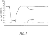
- the relationship between the maximum urethral pressure and the intravesical pressure for normal voiding of the bladder is well defined. With reference to Figure 1 , relaxation of the urethra occurs before the detrusor muscle contracts to cause the intravesical pressure 320 to exceed the urethral pressure 322 during normal voiding.
- the bladder serves two mechanical functions: 1) low-pressure storage and 2) high-pressure voiding.
- Compliance of the bladder is defined as the ratio of the change in volume to the change in pressure, and the static compliance of the bladder is measured during a typical urodynamic evaluation.
- the static compliance index is measured by filling the bladder to cystometric capacity and allowing the pressures to equilibrate for a time period of approximately sixty seconds.
- the static compliance index is calculated by dividing the bladder capacity by the Detrusor pressure at the end of filling.
- a normal bladder will typically exhibit static compliance between 15 and 30 ml/cm H 2 O.
- a low static compliance bladder typically will have a compliance index of less than 10 ml/cm H 2 O.
- a low static compliance bladder typically is poorly distensible and has a high end-filling pressure.
- the intravesical pressure 320 must increase to higher levels to exceed the maximum urethral pressure 324.
- the steady state compliance of the bladder is used to diagnose patients with naturopathic problems such as damage to the lower motor neurons, upper motor neurons, or multiple sclerosis.
- the steady state compliance of the bladder is also used, in some cases, to attempt to diagnose problem of incontinence, including urgency, frequency and cystitis.
- intravesical pressure spikes result from volumetric tissue displacement in response to gravity, muscular activity or rapid acceleration.
- the lack of compliance of the bladder and the urine contained in the bladder with respect to events of high frequency result in minimal fluidic pressure attenuation of the higher frequency pressure wave(s) and results in high intravesical pressures that are directly transmitted to the bladder neck and urethra, which may or may not cause detrusor contractions.
- the urethra may act as a volumetric pressure relief mechanism allowing a proportional volume of fluid to escape the bladder, to lower the intravesical pressure to a tolerable level.
- the urethra has a maximum urethral pressure value, and when the intravesical pressure exceeds the maximum urethral pressure, fluid will escape the bladder. Under these conditions, nerve receptors in the bladder and/or bladder neck and/or trigone trigger a detrusor contraction that may lead to matriculation (frequency) or may subside without matriculation (urgency) or may lead to the intravesical pressure exceeding the maximum urethral pressure resulting in fluid escaping the bladder (incontinence). Under these conditions, waves hitting and/or expanding the bladder wall, may cause a patient with cystitis to exhibit significant pain.
- Incontinence is common in males who have undergone radical prostatectomy, particularly where the sphincter has been compromised.
- attenuation in the bladder reduces the intravesical peak pressures, resulting in less urine leakage.
- the attenuation requirements in these patients can include short duration pressure changes - such as, for example, 50 to 400 ms - and long duration pressure changes - such as, for example, greater than 500 ms - depending on the magnitude of damage to the urinary sphincter.
- the inventors of the present application have recognized that for the vast majority of patients suffering from problems of urinary tract disorders such as frequency, urgency, stress and urge incontinence and cystitis, the cause and/or contributor to the bladder dysfunction is a reduction of overall dynamic bladder compliance rather than steady state bladder compliance.
- These patients may often have bladders that are compliant in steady state conditions, but have become non dynamically compliant when subjected to external pressure events having a short duration of, for example, less than 5 seconds or in some cases less than 2 seconds or even less than 0.5 seconds.
- Reduction in dynamic compliance of the bladder is often caused by some of the same conditions as reduction of steady state compliance including aging, use, distention, childbirth and trauma.
- the anatomical structure of the bladder in relation to the diaphragm, stomach, and uterus causes external pressure to be exerted on the bladder during talking, walking, laughing, sitting, moving, turning, and rolling over.
- Intravesical pressure 320 and the maximum urethral pressure 324 for a patient suffering from stress incontinence due to lack of dynamic compliance in the bladder is illustrated in Figure 3 .
- the bladder does not have sufficient dynamic compliance in that frequency range a spike 326 will occur in the intravesical pressure.
- Intravesical pressure spikes in excess of 120cm H 2 O have been urodynamically recorded during coughing, jumping, laughing or sneezing.
- the intravesical pressure exceeds the maximum urethral pressure value, leakage occurs.
- the urinary retention resistance of the continent individual must exceed the pressure spike.
- Urinary retention resistance can be simplified as the sum total of the outflow resistance contributions of the urethra, bladder neck and meatus. In female patients, it is generally believed that the largest resistance component is provided by the urethra.
- One measure of urinary resistance is the urodynamic measurement of urethral leak pressure. The incontinent individual typically has a urethral leak pressure less than 80cm H 2 O. The decline of adequate urinary retention resistance has been attributed to a number of factors including reduced blood flow in the pelvic area, decreased tissue elasticity, neurological disorders, deterioration of urethral muscle tone and tissue trauma.
- the urethral leak point pressure is determined by filling the bladder with a known amount of fluid and measuring the intravesical and abdominal pressures when there is a visible leak from the urethra while the patient is "bearing-down" (valsalva).
- the measured intravesical leak point pressure typically increases due to the adsorption of some the abdominal energy by the attenuation device. In this case, the patient has to push harder to achieve the same intravesical pressure. Since the abdominal muscles and muscles surrounding the urethra both contract simultaneously during a valsalva maneuver, the measured intravesical leak point pressure and urethral resistance increases when the attenuation device is in the bladder.
- Urinary disorders such as urgency, frequency, otherwise known as overactive bladder, and interstitial cystitis are caused or exacerbated when rapid pressure increases or rapid volume increases or other irritable conditions within the bladder cause motor neurons to send signals to the brain to begin the cascade of events necessary for urination.
- External pressure exerted on the bladder may result in a detrusor contraction that may result in urgency, frequency or incontinence.
- a coughing event 328 induces increased intravesical pressure 320 which results in increased detrusor pressure 330.
- An increase in the detrusor pressure 330 generally is associated with increased urgency, frequency, or incontinence.
- Urinary disorders such as interstitial cystitis or irritable bladder conditions are a chronic inflammatory condition of the bladder wall, which includes symptoms of urgency and/or frequency in addition to pain. Therefore, the problem of a pressure spike in the functionally noncompliant bladder can be further exacerbated by a nearly simultaneous contraction of the bladder and a relaxation of the urethra.
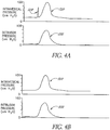
- One method of determining dynamic compliance includes the rapid infusion of a volume of fluid into the bladder with immediate measurement of the intravesical pressure.
- the volume would be more than 50ccs, preferably greater than 100cc and more preferably greater than 200cc.
- the rate of infusion would be less than 10 seconds, preferably less than 5 seconds, and more preferably less than 2 seconds.
- One embodiment in accordance with the present disclosure includes a two lumen catheter placed within the bladder, wherein a compliant balloon is rapidly filled with a non-compliant material, such as saline is infused through one lumen of the catheter. The resulting intravesical pressure is measured from the other lumen of the catheter.
- This infusion can be with a syringe, a mechanically assisted syringe or pump.
- An additional embodiment provides methods and devices for treating and/or compensating for reduced dynamic compliance of the bladder.
- a device having a compressible element is placed within the human urinary bladder, in a manner that allows the compressible element to act as a pressure accumulator or attenuator to attenuate transient pressure events.
- the term accumulator refers generally to devices that attenuate pressure, force, or energy in a given locale by absorbing and/or shifting away said pressure, force, or energy from said locale.
- attenuator refers generally to devices that attenuate pressure, force, or energy by dissipating or dampening said pressure, force, or energy.
- Gases such as atmospheric air, carbon dioxide and nitrogen are very compressible in the pressure ranges typically encountered in the human bladder, and these gases may be used in attenuation devices inserted in the bladder. Furthermore, when compared to the tissues encompassing urine, these gases are significantly more compliant than the immediate environment. The addition of a proportionately smaller volume of unpressurized gas acts as a low rate spring in series with the native fluidic circuit of the urinary tract. Additional information on the basic scientific principles underlying pressure accumulators and methods for controlling transient changes in pressure can be found in E. BENJAMIN WYLIE ET AL., FLUID TRANSIENTS IN SYSTEMS ⁇ 6, 10, 11, 13 (1993 ); the entirety of these sections are hereby incorporated by reference herein and made a part of this specification.
- Accumulators can be designed to keep the pressure from exceeding a predetermined value or to prevent low pressures. Accumulators can be designed to protect against rapid transients as well as against longer-period surges in a system.
- An accumulator is a closed container partially filled with the system liquid and topped with air or gas. The gas may be in contact with the liquid, in which case an air compressor, or gas supply, is used to maintain the proper mass of air or gas, or the gas may be separated from the liquid by a flexible membrane or a piston.
- the accumulator generally operates at the local system pressure.
- valve 302 of the accumulator 300 if the valve 302 of the accumulator 300 is closed abruptly the flow 304 enters the air chamber 306, the air is compressed, and the flow to the main pipeline 308 is gradually reduced as the pressure builds up, thereby provides a way to reduce the peak pressure in the chamber 306, the main pipeline 308, and other downstream plumbing and equipment.
- a single accumulator 300 is assumed to have the same pressure throughout its volume at any given instant.
- the compressibility of the liquid 310 in the vessel 312 is considered negligible compared with air compressibility.
- the exponent n depends on the thermodynamic process followed by the gas 314 in the vessel 312.
- the compression of the enclosed volume of air creates heat that is dissipated into the relatively infinite heat sink of the body.
- the balance of the energy absorbed by the compressed air is simply returned at a different, lower frequency into the fluidic circuit when the gas is allowed to expand, as the surrounding tissues return to their initial positions.
- the addition of adequate local compliance can effectively attenuate transient intravesical pressure spikes to levels below the patient's leak pressure, thus obviating the need for relief by means of volumetric displacement of urine, and/or preventing the stimulation of signals to the brain that cause bladder contractions.
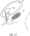
- an attenuation device is placed within the human urinary bladder.
- the attenuation device is intended to be untethered in the bladder and is intended to remain in the bladder for between several hours and one year, between one week and six months, or between one and three months.
- the attenuation device is a small elastomeric air cell with a relaxed (unstretched) volume of between 1 and 500 cc, more preferably between 1 and 100 cc and more preferably still, between 3 and 25 cc.
- the attenuation device is a unitary component but can be comprised of two or more subcomponents.
- the attenuation device has a substantially uniform wall thickness of between 0.64 cm (0.25 inch) to 3 ⁇ m (0.0001 inch), more preferably between 13 ⁇ m (0.0005 inch) and 0.13 mm (0.005 inch), but could be designed to vary greatly, and still perform the intended function.
- attenuation devices having air cells that are free-floating in the bladder have been described.
- air cells or similar attenuation devices could be surgically affixed to the bladder wall through the use of suture, staples and other accepted methods or placed submucosally or intramuscularly within the bladder wall.
- Other embodiments could also include attenuation devices with programmable, variable and adjustable buoyancy by using ballasting, specific inflation/deflation solutions, alternative materials of construction or by other means.
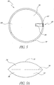
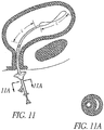
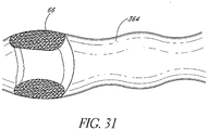
- an attenuation device 66 which comprises a moveable wall such as on an inflatable container 68.
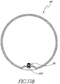
- the inflatable container 68 is illustrated as having a generally circular profile, although other profiles may be utilized in accordance with the present disclosure.
- the diameter of the inflatable container 68 may be varied within the range of from about 0.64 cm (0.25 inches) to about 15 cm (6 inches), in an application of the present disclosure involving the implantation of only a single attenuation device.
- Many embodiments of the inflatable containers 68 will have a diameter within the range from about 2.5 cm (1 inch) to about 7.6 cm (3 inches), with a total volume within the ranges recited above.
- the specific dimensions and configuration of the inflatable container 68 are selected to produce an attenuation device having a desired volume and a desired dynamic compression range, and may be varied from spherical to relatively flat as will be apparent to those of skill in the art based upon the disclosure herein. In certain embodiments, two or three or more discreet inflatable containers 68 are utilized. The sum of the volumes of the multiple containers will equal the desired uncompressed displacement.
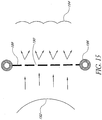
- the inflatable container 68 illustrated in Figures 5 and 5A comprises a flexible wall 70, for separating the compressible contents of the attenuation device 66 from the external environment.
- Flexible wall 70 comprises a first component 74 and second component 76 bonded together such as by a seam 78.
- first component 74 and second component 76 are essentially identical, such that the seam 78 is formed on the outer periphery of the inflatable container 68.
- Seam 78 may be accomplished in any of a variety of manners known in the medical device bonding arts, such as heat bonding, adhesive bonding, solvent bonding, RF or laser welding, or others known in the art.
- the flexible wall 70 formed by a bonded first component 74 and second component 76 define an interior cavity 72.
- interior cavity 72 preferably comprises a compressible media, such as gas, or foam.
- Other media or structures capable of reduction in volume through a mechanism other than strict compression may also be used.
- a material capable of undergoing a phase change from a first, higher volume phase to a second, lower volume phase under the temperature and pressure ranges experienced in the bladder may also be used.
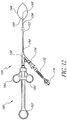
- the attenuation device is preferably expandable from a first, reduced cross-sectional configuration to a second, enlarged cross-sectional configuration.
- the attenuation device 66 may thus be transurethrally deployed into the bladder in its first configuration, and enlarged to its second configuration once positioned within the bladder to accomplish the pressure attenuation function.
- a crossing profile or a greatest cross-sectional configuration of the attenuation device 66 when in the first configuration is no greater than about 24 French (8mm), and, preferably, no greater than about 18 French (6mm). This may be accomplished, for example, by rolling a deflated inflatable container 68 about a longitudinal axis, while the interior cavity 72 is evacuated.
- the interior cavity 72 is filled with the compressible media to produce a functional attenuation device 66.
- the present inventors contemplate fill pressures and volumes of generally less than about 1.5 atmospheres and 50 ml, respectively, and, in some embodiments, less than 0.5 atmospheres and 25 ml, respectively, such as, for example, in the case of an air filled collapsible attenuation device 66.
- the fill pressure and volume are preferably no more than necessary to keep the attenuation device 66 inflated in the absence of pressure spikes. Excessive pressure and volume within the attenuation device 66 may shorten the dynamic range of the attenuation device 66, thereby lessening the sensitivity to attenuate pressure spikes.
- Attenuation device 66 is provided with a self-expandable support structure (e.g. nitinol wire frame), which provides a radially outwardly directed bias.
- a self-expandable support structure e.g. nitinol wire frame
- the resiliency of the material of the attenuation device, and the pressure and volume of the inflation media are preferably matched to produce a compression cycle time which is fast enough to allow the attenuation device to respond to increases in pressure while not have a clinically detrimental effect on voiding.
- the attenuation device's compression cycle preferably bottoms out or reaches a maximum in a sufficiently short period of time as detrussor pressure increases that adverse clinical effects on voiding are minimized or prevented.
- valve 80 is positioned across the seam 78, and may be held in place by the same bonding techniques utilized to form the seam 78. Valve 80 may be omitted in an embodiment in which the attenuation device 66 is self-expandable.
- Valve 80 generally comprises an aperture 82, for receiving a filling tube therethrough.
- Aperture 82 is in fluid communication with the interior cavity 72 by way of a flow path 83.
- At least one closure member 84 is provided for permitting one way flow through flow path 83.
- a delivery system and filling device can be utilized to displace closure member 84 and introduce compressible media into the interior cavity 72.
- the closure member 84 prevents or inhibits the escape of compressible media from the interior cavity 72 through the flow path 83.
- the closure member 84 is preferably movable between a first orientation in which it obstructs effluent flow through the flow path 83 and a second position in which it permits influent flow through the flow path 83.
- the closure member 84 is biased in the first direction.
- forward flow may be accomplished by either mechanically moving the closure member 84 into the second position such as using a filling tube, or by moving the closure member 84 into the second position by exerting a sufficient pressure on the compressible media in flow path 83 to overcome the closure bias.
- the attenuation device consists of an air cell consisting of 46 ⁇ m (0. 0018 inch) thick polyurethane sheets that have been bonded together to form a 6 cm (2 3/8 inch) circle in top view.
- the attenuation device is made from polyurethane and is intended to be inflated to a pressure slightly above atmospheric pressure and a volume less than 50 ml or generally within the range of 69 Pa to 6.9 kPa (0.01 to 1 psi) above atmospheric pressure and less than 25 ml. Integral to the sealing edge 78 of the attenuation device holds a port/valve 80 utilized in the placement, inflation and release of the attenuation device.
- valve 80 Into the port/valve structure 80 is placed the distal end of a rigid fill tube (1.27 mm (0. 050”) OD) 50.
- the valve 80 employed may be one of the valves described in U. S. Patent No. 5,144,708 , which is incorporated herein by reference.
- the attenuation device may be ultrasonically, radio frequency, adhesively or heat sealed in situ following inflation, in which case the valve may be omitted.
- Biocompatible lubricating substances may be used to facilitate the placement of the attenuation device/fill tube within the lumen of the introducer.
- the distal tip of the introducer has been modified to allow a minimally traumatic presentation of the attenuation device to the urethral tissue.
- Biocompatible lubricating substances may be used to facilitate the insertion of the attenuation device into the urethra.
- the attenuation device incorporates biocompatible coatings or fillers to minimize irritation to the bladder wall and mucosa and/or to inhibit the formation of mineral deposits (encrustation).
- the materials can be coated onto the surface or incorporated within the wall of the attenuation device.
- the delivery system 40 is designed to advance an attenuation device 66 (not illustrated) transurethrally into the bladder while in a first, reduced cross-sectional configuration, and to thereafter inflate or enlarge or permit the expansion of the attenuation device to a second, implanted orientation.
- the particular configuration and functionality of the delivery system 40 will therefore be governed in large part by the particular design of the attenuation device 66.
- various modifications and adaptations may become desirable to the particular delivery system disclosed herein, depending upon the construction of the corresponding attenuation device.
- the delivery system 40 comprises an elongate tubular body 42 having a proximal end 44 and a distal end 46.
- Tubular body 42 is dimensioned to transurethrally access the bladder.
- the tubular body 42 preferably has an outside diameter of no more than about 8mm, and, preferably, no more than about 4mm.
- the length of the tubular body 42 may be varied, depending upon the desired proximal extension of the delivery system 42 from the urethra during deployment.
- tubular body 42 In general, an axial length of tubular body 42 within the range of from about 2.5 cm (1") to about 25cm (10") for adult female patients and from about 10 cm (4") to about 76 cm (30") for adult male patients is currently contemplated.
- the tubular body 42 is provided with at least one central lumen 48 extending axially therethrough. Central lumen 48 axially slideably receives a filling tube 50, for filling the attenuation device 66.
- Filling tube 50 comprises a tubular body 52 having a proximal end 54 and a distal end 58.
- An inflation lumen 60 extends throughout the length of the tubular body 52, and is in fluid communication with a proximal hub 56.
- Hub 56 comprises a connector such as a standard luer connector for coupling to a source of inflation media.
- the tubular body 52 has an axial length which is sufficiently longer than the axial length of tubular body 42 to allow the proximal hub 56 to remain accessible to the clinician and accomplish the functions of deploying and filling the attenuation device 66.
- an outer tubular sheath (not illustrated) is slideably carried over the tubular body 42, and is spaced radially apart from the tubular body 52 to define an annular cavity for receiving a rolled attenuation device 66 therein. In this manner, the deflated attenuation device can be rolled around a distal portion of the tubular body 52 and carried within the tubular sheath during transurethral placement.
- proximal retraction of the outer sheath with respect to the tubular body 52 exposes the deflated attenuation device 66.
- a source of inflation media is coupled to the proximal hub 56, and media is introduced distally through central lumen 60 to inflate the attenuation device 66.
- the delivery system 40 is disengaged from the attenuation device 66, such as by retracting the filling tube 50 with respect to the tubular body 42.
- a distal stop surface 47 on tubular body 42 prevents proximal movement of the attenuation device 66 as the filling tube 50 is proximally retracted. Delivery system 40 is thereafter removed from the patient, leaving the inflated attenuation device 66 within the bladder.
- a control 62 is connected by way of a proximal extension 60 to the tubular body 52.
- the control 62 may be in any of a variety of forms, such as a knob or a pistol grip.
- the control 62 may be grasped by the clinician, and utilized to axially advance or retract the filling tube 50 within the tubular body 42.
- the proximal hub 56 is connected to the tubular body 52 by way of a bifurcation 61.
- the central lumen 60 extends through the bifurcation 61 and to the proximal hub 56.
- Proximal extension 60 may comprise a blocked tubular element or a solid element.
- An inflation source 64 such as a syringe filled with a predetermined volume of air or other media may be connected to the proximal hub 56.
- the introducer is suitably sized to easily pass through the urethra (approximately 0.5 to 4mm diameter). Visual feedback is provided to the clinician by means of insertion depth indicators along the longitudinal length of the introducer.
- the introducer may also have an adjustable depth stop that allows the clinician to pre-set the desired insertion depth.
- the attenuation device is released from the fill tube using the tip of the introducer as an opposing force disengaging the attenuation device valve from the fill tube.
- the fill tube is then retracted completely into the lumen of the introducer and the entire delivery system is then withdrawn from the patient.
- the attenuation device is left in place for the clinically indicated period of time.
- One aspect of the present disclosure relates to the delivery of a very flexible, thin walled device. Delivery of an attenuation device is typically accomplished via a suitably sized introducer or possibly through the working channel of an endoscope or cystoscope. However, in certain instances the columnar strength of an attenuation device may make it difficult to be pushed through such channels. A further requirement of any delivery system is that it be atraumatic, and not pose a threat of tissue damage.
- This disclosure addresses such issues, and offers improvements for accomplishing delivery of such attenuation devices as disclosed in co-pending applications U.S. Application Serial No. 60/197,095, filed April 14, 2000 , titled DEVICES AND METHODS FOR BLADDER PRESSURE ATTENUATION, and U.S. Application Serial No. 09/723,309, filed November 27, 2000 , titled DEVICES AND METHODS FOR ATTENUATION OF PRESSURE WAVES IN THE BODY.
- the attenuation device is normally folded on itself along its diameter in order to present a low profile for insertion into, for example, a patients bladder transurethrally. In this configuration the attenuation device has insufficient column strength to withstand the forces of insertion without buckling. If the attenuation device buckles it cannot be inserted. Following insertion the attenuation device is inflated via an inflation tube to which it is pre-mounted. After inflating the inflation tube is detached and the attenuation device is freed.
- various embodiments in accordance with the present disclosure will be described in the exemplary context of transurethral insertion of a delivery system into a patient's bladder.
- an delivery system for the attenuation device which consists of an inner fenestrated tubular member which is provided with an atraumatic rounded tip at its distal end, and an slideably mounted outer coaxial tubular member.
- the rounded tip is shaped such that its proximal end, which is inserted into position in the distal end of the inner tubular member, presents essentially a "ramp" designed to aid ejection of the attenuation device from the fenestration when it is advanced.
- the attenuation device to be delivered is attached to its inflation tube, folded as previously described, and drawn into the inner sheath through the fenestration. Once situated within the fenestration the outer coaxial tubular member is slid forward to close the fenestration, thus containing the bladder within the inner tube.
- delivery system 370 comprises an inner sheath 372, a slideable outer sheath 374, an opening 376 in the inner sheath, and an atraumatic tip 378.
- delivery system 370 comprises an outer sheath 374 that slides backwards and an attenuation device 380.
- the attenuation device 380 is exposed through the opening 376.
- the delivery system 370 comprises an inflation tube 382 that is advanced toward the atraumatic tip 378, thereby causing the attenuation device 380 to be ejected.
- a curved ramp 384 in the delivery system 370 aids the ejection of the attenuation device 380.
- the distal end of the delivery system is inserted through the urethra to an appropriate depth, the outer coaxial tube is slid backwards along the inner tube, thus exposing the fenestration in the inner tube.
- the attenuation device is advanced using the inflation tube and releases easily from the inner tube.
- the attenuation device is inflated, released from the inflation tube, and floats freely in the bladder.
- the attenuation device containment tube 386 is a simple open-ended cylinder.
- the attenuation device 380 is folded as described previously and withdrawn into the containment tube 386.
- the open end of the containment tube 386 would present a potentially traumatic edge to the urethra.
- the open end of the containment tube 386 in this instance has rounded atraumatic end 378.
- This end 378 contains slits 388 which, on sliding the containment tube 386 backwards allows the end 378 to open, thus allowing deployment of the attenuation device 380 from the containment tube 386.
- the slits 388 open and present little barrier to the deployment of the attenuation device.
- the attenuation device is delivered percutaneously through the pelvis into the bladder. Similar to percutaneous access of arteries or veins, a needle is inserted through the skin and into the bladder. A guide wire is placed through the needle and the needle is removed leaving the guide wire in place. The delivery system and attenuation device are pushed into the bladder over the guide wire. The attenuation device is deployed and the delivery system and guide wire are removed. Guidance using ultrasound can also be employed to help guide the delivery system into the bladder.
- a removable delivery system is used to deliver, deploy, and fill the attenuation device.
- the delivery system can take the form of the system taught by U.S. Patent No. 5,479,945 , titled method and a removable device which can be used for the self-administered treatment of urinary tract infections or other disorders, issued January 2, 1996, the disclosure of which is incorporated in its entirety herein by reference.
- FIG. 7A and 7B there is illustrated one disengagement sequence for deploying the inflatable attenuation device 66 from the delivery system 40 in accordance with one aspect of the present disclosure.
- the delivery system 40 is initially configured with the filling tube 50 positioned within the valve 80.
- the distal end 46 of outer tubular body 42 is dimensioned such that it will not fit through the aperture 82 of valve 80.
- the attenuation device 66 is inflated through filling tube 50.
- the filling tube 50 is proximally retracted following inflation so that it disengages from the valve 80. This is accomplished by obstructing proximal movement of the attenuation device 66 by stop surface 47 on the distal end 46 of tubular body 42. The attenuation device 66 is thereafter fully disengaged from the delivery system 40, and the delivery system 40 may be removed.
- Valve 80 comprises a tubular wall 81, having an aperture 82 in communication with a flow path 83. At least one closure member 84 is attached to the tubular wall, and extends across the flow path 83.
- closure member 84 comprises a first and a second duck bill valve leaflets 86 and 88 which are attached at lateral edges 90 and 92 to the tubular wall. The leaflets 86 and 88 incline medially in the distal direction to a pair of coaptive edges 94 and 96.
- This configuration allows forward flow through flow path 83 to separate coaptive edges 94 and 96, thereby enabling inflation of the attenuation device 66.
- the inflation media within the attenuation device 66 in combination with natural bias of the leaflets 86 and 88 cause the leaflets to coapt, thereby preventing effluent flow of inflation media through the flow path 83.
- tubular body 81 and first and second leaflets 86 and 88 may be manufactured from any of a variety of materials which will be apparent to those of skill in the art.
- tubular body 81 may be made from polyurethane such as by extrusion.
- Leaflets 86 and 88 may be made from any of a variety of flexible materials such as polyurethane, silicone, or polyethylene, and may be bonded to the tubular element 81 using adhesives, heat bonding, or other bonding techniques known in the art.
- Suitable valves include the valve manufactured by Target Therapeutics and sold as the DSB silicon balloon to fill aneurysms and arterial-venous malformations.
- the bushing 249 is RF welded to the inflatable container 68 prior to installing the valve 80.
- the duckbill valve 80 is bonded to the bushing 249 after welding.
- the mandrel is installed during welding, resulting in a polished surface with an air-tight seal along the inside of the tube.
- closure is accomplished by two coaptive edges on distal end 106 of tubular body 81.
- This construction is sometimes referred to as a flapper valve.
- the tubular body 81 in this embodiment is formed by a first wall 96 and a second wall 100 which are bonded or folded along a first edge 102 and a second edge 104 to define a flow path 83 extending therethrough.
- the free distal ends of first and second walls 96 and 100 at the distal end 106 form coaptive leaflets, which may be opened under forward flow pressure through the flow path 83 and will inhibit or prevent reverse flow through the flow path 83.
- the proximal end of the flow path 83 on the flapper valve of Figure 8B or other valve structure may be reinforced such as by a reinforcing tube 108.
- Reinforcing tube 108 may be manufactured in any of a variety of ways.
- reinforcing tube 108 may be extruded from various densities of polyethylene, Pebax, polyurethane, or other materials known in the art.
- Reinforcing tube 108 may be desired to maintain patency of the pathway to the valve 80, particularly in an embodiment adapted for coupling to a deflation and removal system as will be discussed.
- the reinforcing tube 108 may be removable and used to prevent sealing of the valve during the manufacturing process and may also ease the placement of a fill tube in the valve. This reinforcing tube 108 is removed after the manufacturing process is complete, or may be removed before, during, or after the fill tube is placed.
- annular sealing ring 110 is provided on the interior surface of the tubular body 81.
- Annular sealing ring 110 is adapted to provide a seal with the filling tube 50, to optimize the filling performance of the attenuation device.
- Sealing ring 110 is thus preferably formed from a resilient material such as silicone or polyurethane and dimensioned to slideably receive the filling tube 50 therethrough.
- sealing with the fill tube may be enhanced by restricting the aperture diameter without the use of a distinct sealing ring 110. Exemplary dimensions of the attenuation device 66 are shown in Figure 33A .
- the valve may also be placed in the body of the attenuation device, rather than in the seam.
- the through hole 258 has a diameter of 1.57 mm (0.062 inches).
- the inflation channel 256 has a diameter of approximately 1.6 to 1.78 mm (0.063 to 0.070 inches).
- the valve can be placed in any number of ways including the methods described in U.S. Patent No. 5,248,275 , titled Balloon with flat film valve and method of manufacture, issued September 28, 1993, and U.S. Patent No. 5,830,780 , titled Self-closing valve structure, issued November 3, 1998; both of these patents are hereby incorporated by reference herein and made a part of this specification.
- the valve 80 has a fill/plug 250.
- the mandrel is installed during welding, resulting in a polished surface with an air-tight seal along the inside of the tube.
- the attenuation device 66 is preferably also removable from the bladder. Removal may be accomplished in any of a variety of ways, depending upon the construction of the attenuation device. Preferably, removal is accomplished transurethrally. In one embodiment, removal is accomplished by reducing the attenuation device 66 from its second enlarged profile to its first, reduced profile so that it may be withdrawn transurethrally by a removal system. The removal system will be configured differently depending upon whether reduction from the second profile to the first profile is accomplished by deflation, or by compression. One embodiment of a removal system utilized to remove an inflatable attenuation device 66 will be described below in connection with Figure 12 .
- the removal procedure involves dissolving or degrading the material or a portion of the material of the attenuation device 66 in situ.
- Material selection and wall thickness of the attenuation device 66 may be optimized to provide the desired useful life of the attenuation device 66, followed by dissolution in the aqueous environment of the bladder.
- dissolution or deflation may be catalyzed or accelerated by an accelerating event such as a change in pH or introduction of an initiator or accelerator into the bladder, or reduction of pressure.
- Attenuation devices having a predetermined dwell time after which they are automatically voided advantageously eliminate the need for a removal procedure.
- Such temporary attenuation devices can be manufactured in a variety of ways in accordance with the present disclosure, such as through the use of bioabsorbable or permeable materials.
- the entire wall of the inflatable container 68 is made from an absorbable material.
- absorbable means any material which will dissolve, degrade, absorb or otherwise dissipate, regardless of the chemical mechanism, to achieve the purpose recited herein.
- only a portion of the flexible wall 70 or other portion of the attenuation device such as the valve is made from an absorbable material.
- one or more seams such as seam 78 can be bonded by a dissolvable or absorbable material that is designed to fail after a predetermined time in the aqueous environment of the bladder.
- the resulting deflated components from any of the foregoing time limited embodiments can thereafter either be expelled during normal voiding, or can remain in the bladder in a deflated state until removed using a removal system.
- the material or portion of the inflatable container 68 is made from a gas permeable material. As the gas dissipates from the inflatable container, its ability to spontaneously void increases.
- the attenuation device is filled with approximately 20 ml of gas and the attenuation device's material allows approximately 15 ml of gas to permeate out of the attenuation device over certain time intervals, such as, for example, one, three, six, or twelve months. Once the volume remaining is less than approximately 5 ml, the attenuation device is normally voided.
- the predetermined dwell time within the bladder can be influenced by a variety of design factors, including the formulation of the absorbable material and the physical shape, thickness and surface area of the absorbable component.
- design factors including the formulation of the absorbable material and the physical shape, thickness and surface area of the absorbable component.
- absorbable polymers which can be used in accordance with the present disclosure are known in the absorbable suture arts.
- absorbable multifilament sutures such as DEXON sutures (made from glycolide homopolymer and commercially available from Davis & Geck, Danbury, Conn.), VICRYL sutures (made from a copolymer of glycolide and lactide and commercially available from Ethicon, Inc., Sommerville, N.J., and POLYSORB sutures (also made from a copolymer of glycolide and lactide and commercially available from United States Surgical Corporation, Norwalk, Conn.) exemplify materials known in the industry and characterized as short term absorbable sutures.
- the classification short term absorbable sutures generally refers to surgical sutures which retain at least about 20 percent of their original strength at three weeks after implantation, with the suture mass being essentially absorbed in the body within about 60 to 90 days post implantation.
- Certain bioabsorbable elastomers may also be used to form the attenuation devices or fuses in accordance with the present disclosure.
- the elastomers can be melt-processed, for example by extrusion to prepare sheets, plugs or tubular structures.
- the copolymers can be injection molded to fabricate intricately designed parts, or compression molded to prepare films.
- melt-processing techniques see, for example, F. Rodriguez, Principles of Polymer Systems, Chapter 12 (McGraw Hill 1970 ).
- the bioabsorbable elastomers can also be solvent cast to prepare thin films.
- Solvent casting can be accomplished using conventional methods such as first dissolving the copolymer in a suitable solvent to make a solution, then casting the solution on a glass plate to make a film, and then evaporating the solvent from the cast film.
- the copolymers can be lyophilized to prepare foams. Lyophilization can be accomplished by first dissolving the copolymer in an appropriate solvent, freezing the solution, and then removing the solvent under vacuum. The set of appropriate solvents include p-dioxane. Lyophilization techniques to prepare films are described in Louis Rey, Aspects Theoriques Et Industriels De La Lyophilization (1964 ).
- copolymers in which segments or sequences are composed of both p-dioxanone and lactide repeating units.
- segmented copolymers are stated to be less crystalline than the block or graft copolymers previously known in the art and, therefore, yield materials with good strength, but shorter BSR ("Breaking Strength Retention") profiles, faster absorption rates, much longer elongations and lower stiffness than the block copolymers.
- BSR Bitking Strength Retention
- a wide variety of copolymers of polylactic and polyglycolic acids are also known in the art, particularly for use with absorbable orthopedic screws and fasteners.
- Attenuation devices may be time rated, such as 15 days, 30 days, 45 days, 90 days, 180 days or other as may be desired.
- the deflated and or partially dissolved attenuation device will be transurethrally expelled within a few days of the expiration of the rated time period from the time of implantation.
- the removal system 150 comprises an elongate tubular body 152 which extends between a proximal end 154 and a distal end 156. Tubular body 152 is dimensioned to transurethrally access the bladder.
- the removal system 150 is adapted for use in conjunction with standard urological cystoscopes (e. g. approximately 4.7 - 8 mm (14-24 French)), having minimum working channels of approximately 1.8 to 6.0 mm
- standard urological cystoscopes e. g. approximately 4.7 - 8 mm (14-24 French)
- minimum working channels of approximately 1.8 to 6.0 mm
- removal system 150 in one embodiment has an overall length of approximately 76cm and a useable length of approximately 60 cm.
- tubular body 152 may be manufactured in accordance with any of a variety of techniques well understood in the catheter and other medical device manufacturing arts.
- tubular body 152 is extruded from a biocompatible material such as TFE, having an inside diameter of approximately 2.3 mm (0.09 inches) and a wall thickness of about 0.25 mm (0.01 inches).
- Y-adaptor 158 carries a control 160 for controlling the retrieval system as will be described.
- Control 160 in the illustrated embodiment comprises a thumb ring 162 which is slideably carried with respect to a pair of finger rings 164. Axial movement of the thumb ring 162 with respect to the finger rings 164 enlarges or retracts a retrieval loop 166 extending distally from distal end 156 of tubular body 152.
- Retrieval loop 166 is adapted to surround the inflated attenuation device 66.
- the loop 166 has an enlarged diameter of about 27mm, and comprises a wire such as 0.41 mm (0.016 inch) diameter stainless steel cable wire.
- the loop 166 is opened once the distal end 156 of the tubular body 152 has reached the bladder.
- the loop 166 is positioned around the attenuation device 66, and the proximal control 160 is manipulated to tighten the loop 166 around the attenuation device 66.
- a deflating tube 168 preferably having a sharpened distal tip 169 thereon, is distally advanced through the wall of the attenuation device 66.
- Distal advancement of the deflating tube 168 may be accomplished by distally advancing a proximal control, such as control 172.
- the distal tip 169 is in fluid communication with a connector such as a standard luer adaptor 170 through a central lumen (not illustrated), so that an empty syringe or other device may be connected to the connector 170 and used to evacuate the contents of the ensnared attenuation device 66.
- the control 160 may be manipulated to pull the collapsed attenuation device 66 into the distal end 156 of the tubular body 152.
- the removal system 150 having the reduced attenuation device 66 therein or carried thereby may be transurethrally removed from the patient.
- the proximal controls 160 and 172 may be combined into a pistol grip or other configuration. Controller 172 or control 160 may additionally control deflection of the distal end 156 of the tubular body 152, or control rotation of the plane of the loop 166.
- the removal system 150 preferably accomplishes the basic functions of enabling the location of the attenuation device 66, capturing the attenuation device, reducing the attenuation device in size and removing the attenuation device from the bladder.
- the capturing step may be accomplished by visualizing the attenuation device through the urological cystoscope, or by "blind” techniques, such as, for example, light reflectance, impedance, suction, ultrasound, passive induced microchip, or the magnetic locator described in connection with Figures 21, 22, 23 , below.
- FIG. 13 and 13A there is illustrated a top plan view of one embodiment of an attenuation device 180 in accordance with one aspect of the present disclosure.
- the attenuation device 180 comprises an inflatable body 68 generally as has been described.
- An outer seam 78 may be provided with a valve 80.
- an inner seam 182 defines a central region 184.
- the outer seam 78 and inner seam 182 define a generally torodial-shaped inflatable container 68.
- the central region 184 may comprise either a membrane or a central opening, depending upon the desired performance characteristics.
- the center hole may assist in the placement and location of the attenuation device within the bladder, permit additional baffling of the pressure waves within the bladder, minimize the attachment to the bladder wall by surface tension between the attenuation device and the bladder wall, and allow for urine flow through the hole in the event that the attenuation device is in or near the bladder neck.
- the central region 184 comprises a baffle 186.
- the baffle 186 comprises a membrane 188 having a plurality of apertures 190 therein.
- approximately nine round apertures 190 are provided, each having a diameter of about 0.5 cm (0.2 inches). Generally at least about 9 apertures 190 are provided, and many embodiments include anywhere from about 1 to about 1000 apertures.
- the optimal number of apertures 190 and sum of the area of the apertures 190 compared to the total area of the baffle 186 may be optimized depending upon the desired performance characteristics. Apertures may have any of a variety of configurations, such as round holes, irregular openings, slits or others.
- a wave diffuser function of the baffle 186 is schematically illustrated in Figure 15 .
- a wave front 192 may be generated by any of a wide variety of events, such as coughing, sneezing, laughing, physical movement, muscle spasms or others as is understood. Since urine comprises essentially non-compressible water, and due to the low dynamic compliance of the bladder the wave front 192 will propagate rapidly through the bladder to impact structures such as the trigone area and the urethra. Apparent transient pressure spikes as high as 80cm H2O or greater can be experienced during normal activities. In addition to reducing the pressure caused by pressure events such as coughing, the attenuation devices discussed above can also provide a baffle that distributes the wave across the bladder distributing and reducing the focused wave front that contacts the bladder neck.
- the baffle 186 functions to disrupt the unitary progression of the wavefront 192.
- the prediffusion wave front 192 is thus interrupted into a plurality of post-diffusion wave fronts 194 by the baffle 186.
- the sum of the resulting post-diffusion wave fronts 194 is essentially equal to the prediffusion wave front 192, the greater dispersion of force accomplished by the baffle 186 is believed by the inventors to reduce the apparent magnitude of the wave front 192 as experienced by target tissue within the bladder.
- the baffle 186 may be constructed in any of a variety of manners and still accomplish the intended result.
- the attenuation device 180 illustrated in Figures 13 and 14 comprises a generally toroidal-shaped inflatable container, any of a variety of other support structures may be utilized to maintain the baffle 186 in a useable configuration.
- the support 196 can comprise an inflatable tube, a resilient material such as nitinol wire, or other support structure as may be desired.
- Certain embodiments in accordance with the present disclosure include a device that is mechanically in contact with the mucosal tissue of the bladder or urethra.
- the sensation caused by the mechanical contact causes nerve receptors to tighten the urethral muscles increasing urethral resistance, thus, reducing or eliminating incontinence events.
- FIG 16 there is illustrated a variety of shapes for the attenuation device 66, of the inflatable container variety.
- the devices used in embodiments in accordance with the present disclosure may take many shapes. In some instances it may be desirable for manufacturing purposes to have the shape resemble dip-molded devices like condoms, surgical glove fingers, or children's toys.
- Attenuation devices include torroid like shapes, similar in form but not size to donuts and inner tubes; spoked wheel forms; horseshoe-like forms; mushroom-like forms; and banana-like forms.
- the attenuation devices in accordance with the present disclosure can be dip molded or extruded in a plurality of biocompatible materials. Furthermore, the attenuation devices can be fabricated from a variety of multi-layer composites or produced by a number of different manufacturing processes. Here, the designs of the attenuation devices are characterized by minimization and control of the gas and moisture vapor permeabilities in and out of the attenuation device.
- the gas and moisture vapor permeabilities of any given material will vary depending on the conditions surrounding the material.
- an attenuation device comprised of a certain material can have different gas and/or moisture permeabilities within the bladder than at standard temperature and pressure.
- the intravesical environment includes exposure to pressure variations in the range of from about 0.34 kPa (0.05 psi) to about 1.7 kPa (0.25 psi) at rest, with transient pressure spikes as high as 14 kPa (2 psi) or more.
- the body temperature is normally about 37°C (98 degrees F) or greater, and the attenuation device resides in 100% humidity.
- Long term efficacy of the attenuation device may be compromised if there exists any fluid or vapor exchange through the wall of the attenuation device in situ.
- the relative impermeability of the wall under normal intravesical conditions is preferably accomplished without losing the compliancy of the attenuation device which allows it to compress within folds of the bladder as is described elsewhere herein.
- the wall of the attenuation device will comprise at least one gas barrier layer and at least one moisture barrier layer.
- gas barrier materials e. g. polyvinylidene chloride, ethyl vinyl alcohol, fluoropolymers, etc.
- These materials are generally relatively stiff, have a high moisture vapor permeability, and have low impact strength.
- a variety of relatively flexible materials, having high moisture barrier characteristic and optionally high impact strength that can be formed into thin film sheets include but are not limited to: polyamide, polyethylene, polypropylene, polyurethane, polyamide/polyester copolymer, polystyrene/polybutadiene copolymer, etc.
- at least one layer on, or the entire attenuation device comprises a blend of a barrier material and a flexible high impact strength material (e. g. polyurethane/polyvinylidene chloride, polyethylene/ethyl vinyl alcohol, etc.).
- the attenuation device typically has two or more layers or barriers.
- the attenuation device can have a gas barrier layer and a moisture barrier layer.
- An additional layer may be included to enhance the structural integrity of the attenuation device.
- the attenuation device has an outer layer comprising a gas barrier and an inner layer comprising a moisture barrier.
- the attenuation device has an outer layer comprising a moisture barrier and an inner layer comprising a gas barrier.
- the attenuation device can have three, four, five, or more layers.
- the attenuation device has a gas barrier layer, a moisture barrier layer, and one or more layers composed of at least one high impact strength material.
- the attenuation device has multiple gas barrier layers arranged in a nonconsecutive arrangement.
- the attenuation device has multiple moisture barrier layers arranged in a nonconsecutive arrangement.
- the other layers of the attenuation device can include high impact strength material layers and/or other types of barrier layers.
- the overall thickness of the wall is preferably minimized, and will often be no more than about 0.76 mm (0.03 inches).
- the wall will be no more than about 0.15 mm (0.006 inches), and, in some implementations, is no more than about 76 ⁇ m (0.003 inches thick).
- An outer layer may comprise a soft, conformable material such as polyurethane, EVA, PE, polypropylene, silicone or others, having a thickness within the range of from about 64 ⁇ m (0.0025 inches) to about 0.69 mm (0.025 inches).
- the adjacent barrier layer may comprise EVOH, PVDC or other materials in a thin film such as from about 5 microns to about 25 or 30 microns thick. If the attenuation device is fabricated by bonding two sides together, a bonding or tie layer may be provided on the barrier layer.
- the layers comprising polyurethane, EVA or others may be used, having a thickness of preferably no greater than about 25 ⁇ m (0.001 inches). Layers of less than about 20 ⁇ m (0.0008) are preferred, and layer thicknesses on the order of from about 7.6 to about 13 ⁇ m (0.0003 to about 0.0005 inches) are contemplated.
- the layers of the attenuation device can be formed in any number of ways known to those skilled in the art, including, but not limited to, lamination, coextrusion, dip molding, spray molding, or the like, etc. As discussed above, the layers of the attenuation device can be formed from various materials. With respect to those attenuation devices that are formed by laminating two or more layers together, various different laminating techniques known to those skilled in art can be used, including, but not limited to, heating, solvents, adhesives, tie layers, or the like.
- the material may not need to be elastomeric at all for the attenuation device to function.
- the materials chosen for use in embodiments in accordance with the present disclosure are to be sufficiently flexible in the thickness ranges dictated by the selected designs.
- the attenuation device's material is able to transmit the pressure to the contained air or pressure management construct and respond sacrificially as one of the most compliant members of the urinary system.
- Figure 16A illustrates a toroidal embodiment, in which a plurality of central spokes are provided.
- Figure 16B illustrates a crescent or "C" shaped attenuation device. Any of a variety of spherical, oval, elliptical or other shapes may be utilized such as those illustrated in Figure 16C , in which the greatest length dimension of the inflated attenuation device is within the range of from about 1 to about 5 times the smallest cross-section.
- Figure 16D illustrates a less arcuate variety as shown in Figure 16B .
- the attenuation device 66 may take any of a variety of forms which provides a sufficient volume to achieve the desired attenuation function, and which will minimize or eliminate risk of loss or obstructing outflow through the urethra.
- Attenuation device embodiments in accordance with the present disclosure for absorbing transient pressure changes include diaphragmatic structures, rigid structures both shape changing and rigid with a coating or a bellows or bellows-like structure that can dampen pressure waves in an organ, chamber or cavity of the body as stand alone attenuation devices or as part of the wall or structure of the organ of interest.
- a mechanically assisted attenuation device is in Figures 17A and 17B.
- Figure 17A is a mechanical bellows that is in a normally extended position.
- the pressure within the bellows is reduced such that the bellows normally retains its extended position, but will compress when external pressure is exerted on it.
- the bellows could be made from plastic or metal, such as, for example, titanium or stainless steel from Senior Flextonics, Inc. Sharon, MA.
- the bellows may be sealed, or covered in a material that allows for the reduction of air pressure within the structure.
- the bellow attenuation device 200 comprises a membrane 202, which is collapsible in an accordion fashion.
- the membrane 202 may be self-supporting, or may be provided with an internal or external frame.
- the frame may comprise any of a variety of structures, such as a simple spring aligned in parallel with the longitudinal axis of the bellow, or pivotably moveable structures such as an axially compressible wire pantograph as will be understood in the art.
- a mechanically-assisted attenuation device 210 in accordance with the present disclosure.
- a compressible tubular wall 212 having closed ends 214, 216 is supported by a self-expanding tubular frame 218.
- Any of a variety of self-expanding tubular or spherical frame structures may be utilized, such as "zigzag" wire frames well known in the abdominal aortic aneurysm graft arts.
- the abdominal aortic aneurysm graft application generally requires a relatively high, radially outwardly directed force, the present application would preferably be compressible with a relatively low compressive force (i.e., low radial force).
- FIG. 19A and 19B there is illustrated another layout for the inflatable attenuation device 66 in accordance with the present disclosure.
- a plurality of attenuation devices 67 are connected by a common flow path 65, so that the plurality of attenuation devices 67 can be inflated through a single fill port.
- a plurality of self-expanding attenuation devices are connected by a suture, Nitinol wire, or other tether, thereby minimizing the crossing profile and/or maintaining a constant crossing profile for an attenuation device of any desired total inflated volume.
- Figures 20-23 illustrate a magnetic locating system for enabling "blind” retrieval without the use of a cystoscope.
- the removal system is inserted into the urethra for intravesical capture, deflation, and extraction of the attenuation device.
- the removal system utilizes a magnet whose polarity and flux path is oriented in a manner to ensure predictable attraction and coupling of a magnet-containing attenuation device to the removal system.
- the removal system is coupled back to the attenuation device, and the attenuation device may be punctured and deflated using the jaws of biopsy-like forceps (or other solution suitable for deconstructing the device) located at the distal end of the removal system.
- residual gas may be passively vented into the bladder or through the retriever body. Once deflated the attenuation device may be withdrawn through the urethra attached to the removal system or allowed to pass out of the bladder as part of the urine flow.
- an attenuation device 230 such as an inflatable balloon 229 as has been described previously herein.
- the attenuation device 230 is provided with a valve 232 and a locating element 234.
- Locating element 234 may be any of the variety of structures which enable location of the attenuation device 230, preferably without the need for direct visualization.
- the locating element 234 is one or more magnets 236.
- the magnet 236 comprises an annular ring, for surrounding the flow path 83.
- a corresponding magnet 238 having reversed polarities from the polarity of the magnet 236 is provided on the distal end of a catheter 240. The attractive forces of the opposing polarity magnets 236 and 238 will cause the catheter 240 to couple on to the attenuation device 230, as illustrated in Figure 22 , when the catheter 240 is positioned in the vicinity of the attenuation device 230.
- At least one lumen 242 places the attenuation device 230 in fluid communication with the catheter 240 when the locating element 234 is coupled to the catheter 240.
- This lumen 242 may be utilized to either introduce inflation media or remove inflation media from the attenuation device 230.
- the valve 232 is a ball valve, which is biased in the closed orientation.
- a valve actuator 234 may be advanced distally through the lumen 242 to displace the valve 232 and enable infusion or removal of inflation media. Following the desired volume of infusion or removal of inflation media, the valve actuator 234 may be proximally retracted, to enable the valve to close under its own bias. See Figure 23 .
- the opposing magnets 236 and 238 may be utilized solely as a locating structure, such that an additional locking element (not illustrated) may be utilized to lock the catheter 240 on to the attenuation device 230. This may be desirable if the strength of the bond formed between the two magnets is insufficient to keep the attenuation device 230 coupled to the catheter 240 during the filling or removal steps. In addition, following deflation of the attenuation device 230, the catheter 240 will generally require a relatively strong coupling to the attenuation device 230 to retrieve the attenuation device 230, as will be apparent to those of skill in the art in view of the disclosure herein.
- the removal system is provided with one or more ultrasound transducers near a distal end thereof.
- An air filled attenuation device should strongly reflect an ultrasound signal, in a manner similar to the reflection achieved at an air-water interface.
- a removal system provided with a deflectable distal tip and ultrasonic capabilities should be able to navigate through the bladder to locate an attenuation device without the need for visualization.
- the removal system may additionally be provided with a grasping element, such as two or more opposing mechanical graspers, and/or a vacuum lumen, for attaching to the surface of the attenuation device using suction. Once attached, the attenuation device can be pierced and transurethrally withdrawn.
- an attenuation device that may assume multiple shapes during the course of its use.
- the attenuation device may be completely deflated for introduction and inflated to varying degrees after introduction.
- the attenuation device may be adjusted through the inflation/deflation of secondary or multiple containment cells for such purposes as ballasting or the addition of a diagnostic, therapeutic or signaling substance. This may occur through multiple uses of a single, or single uses of a multi lumen, multi ported structure or combinations thereof.
- the delivery system and the removal system of the attenuation device or accumulator are two separate instruments.
- the delivery system and the removal system are implemented using a single instrument.
- an endoscope may be used to launch and retrieve the device (i.e. attenuation device, accumulator, etc.).
- the distal tip of the delivery system may be straight, pre-curved, malleable, or steerable (e.g., by pull wires) in order to facilitate delivery and/or release of the device.
- the separation of the attenuation device from the fill tube may be accomplished using the wall of the urethra or neck of the bladder as a mechanically resistant body.
- the delivery system may consist of a single tubular element, a series of concentric tubular elements, a series of non-concentric tubular elements, an extruded element, a spirally wound guidewire element, or any combination of the aforementioned elements arranged in a manner to provide the desired functions.
- irritation concerns are addressed through the use of coatings or fillers to physically or chemically modify the attenuation device in whole or part in order to modulate characteristics such as lubricity and the ability to inhibit the deposition of materials present in the urinary tract.
- substances such as sulfated polysaccharides may be used before, during, or after introduction to the patient.
- the use of a plurality of construction materials with unique surface properties may also be used for this purpose.
- the attenuation device includes a portal that spans the distance from the internal aspect to the external aspect that allows for the location of an erodable substance that would allow for the deflation or deconstruction of the attenuation device after exposure to urinary tract conditions for a prescribed period of time.
- This approach may also be used for the programmed bolus release of single or multiple therapeutic, diagnostic or signaling substances from single or multiple chambers within the attenuation device.
- the attenuation device is equipped with a valve/port that is programmable, self-regulating or responsive to stimuli, which may or may not be physiological. Telemetry, physical connection or remote signaling may be used to elicit a desired response.
- the attenuation device accepts, captures, and/or translates physical forces within the urinary tract to energize a site within the attenuation device for the positive displacement of substances outside the boundary of the attenuation device in either continuous or bolus presentation.
- a port/valve that is not associated with the sealing edge of the attenuation device.
- an attenuation device that includes a thin, pliable safety tether 332 long enough to extend from the attenuation device and exit from the meatus. See Figure 24 .
- the tether can be constructed of accepted materials such as those used in the manufacture of sutures, catheters and may also possess antimicrobial properties.
- the distal end of the tether may be terminated with a lightweight pendant 334 of sufficient bulk to prevent ingress of the entire tether into the urethra.
- the pendant may be temporarily affixed to the patient's pelvic region.
- the tether may be used to remove or deconstruct the attenuation device, and the tether provides the patient with the capability of instant removal of the attenuation device in the event the patient feels compelled to extract the attenuation device.
- an attenuation device that is a chambered structure consisting of multiple subchambers for multiple functions. See Figures 25 and 25A-C .
- the primary attenuation device 336 may or may not be fluidically connected to the secondary device 338.
- the fluidic connection 340 also acts as a tether with sufficient service loop to allow the secondary device 338 to be placed into the urethra while the primary attenuation device 336 remains untethered in the bladder 63, located above the pubic bone 69.
- gas within the primary attenuation device 336 compresses proportionally with the external load.
- the compressed gas is then allowed to transfer to the secondary device 338, dwelling in the urethra, and causing a proportional expansion of the secondary device 338.
- the design of the secondary device 338 directs expansion in an outward radial direction, transverse to the longitudinal axis of the urethra, thus augmenting the natural inward radial contraction of the urethra.
- This type of "on demand" synchronous resistance augmentation may be much more effective than other forms of passive or patient controlled augmentation systems.
- Another benefit of this embodiment is that the synchronous outward radial forces may help to positionally stabilize the secondary device within the urethra. Passive devices must maintain a constant retention capability (force or displacement of tissue) sufficient to resist the maximum expulsion forces at all times. This level of retention may lead to patient discomfort and cause long-term tissue damage.
- compression force (Fcomp) 342 equals the sum of ingress force (Fingress) 344 and the egress force (Fegress) 346.
- the intravesical pressure 348 exhibits a rapid rise time and a rapid decay time.
- the secondary device pressure 350 exhibits a rapid rise time and a delayed decay time.
- Figure 26 illustrates the effect of an attenuation device on the intravesical pressure.
- the intravesical pressure 352 with the attenuation device exhibits delayed rise and decay times and remains below the leakage pressure of 80 cm H20. This is contrast to the intravesical pressure 354 which exceeds the leakage pressure.
- the attenuation device 66 is anchored to the bladder wall 356.
- the attenuation device 66 is part of a tranurethrally-placed dynamic compliancy measurement catheter 358.
- the attenuation device may resemble a small three-spoked automotive steering wheel, or a rotating toroidal space station. See Figure 16A .
- the outer ring would contain the attenuation device; the inwardly radiating spokes would provide fluid conduits and mechanical support for the secondary device attachment.
- the attenuation device may also incorporate one or more shape holding super elastic wire members to aid in positional stability.
- the secondary device could resemble the distal tip section of a small diameter angioplasty device and be affixed to the central hub.
- a secondary device inflation/deflation response can be design regulated. For example, it may be beneficial to inflate the secondary as quickly as possible, but induce a response lag in the deflation/inflation cycle to protect against a second cough, sneeze or sudden mechanical shock.
- a pressure compensator or bladder trainer that can be implanted within a treatment site, such as, for example, the abdominal cavity, and be hydraulically or pneumatically connected to the bladder or be installed as a component of the bladder wall.
- the device would be constructed of a rigid external enclosure to shield the compressible elements from abdominal forces.
- the function of this embodiment would be not only to manage the transvescular pressure in treatment of a clinical insult, but also to introduce pressure waves either outside or inside the bladder in order to increase the muscle tone, compliance or affect the neuromuscular elements of the bladder.
- Certain embodiments in accordance with the present disclosure provide significant advantages over prior art devices. These advantages include but are not limited to: significant reductions in bladder dysfunction related events; the ability to retrain a bladder with other than normal compliance; no patient interaction required to operate or maintain the attenuation device; patient is allowed to void in a normal fashion; no infection conduit between the bladder and the distal end of the meatus; minimal sensation generated by the attenuation device; low cost to manufacture; cost effective solution for patient when compared to existing treatments; and ease of installation and removal for clinician.
- a device can be used in combination with the fill tube/introducer to measure the dynamic compliance of the bladder.
- One lumen of the fill tube can be used to rapidly inflate the device, while pressure measurements of the bladder are made via a second lumen.
- the volume is expanded by at least about 30cc or 50cc up to as much as 200cc in a time period of from about 0.5 to 10 seconds to measure the dynamic compliance of the bladder.
- intravesical devices such as Foley catheters, intravesical infusers, such as those described in WO1998US0021368, filed October 9, 1998 , titled intravesical infuser (the disclosure of which is incorporated in its entirety herein by reference), or the ends of urethral stents to facilitate delivery, to treat multiple symptoms, or to enhance the performance of either device.
- the attenuation device could work in combination with intravesical infusers, to time the release of medications relative to pressure events within the bladder.
- an atraumatic method of measuring intravesical pressure without the need for any external connection by placing a pressure transducer and telemetry device within the attenuation device. This secures the transducer within the bladder and prevents the need to attach the transducer to the bladder wall.
- Embodiments in accordance with the present disclosure are not limited to intravesical devices, but also include devices and methods for controlling pressure transients in other organs of the body, as will now be discussed.
- FIG 29 which shows a tubular attenuation device 66 in a vessel 360
- one embodiment in accordance with the present disclosure is intended for use in cardiovascular applications to modulate pressure waves to protect the heart and/or the vasculature from being damaged due to exposure to the pulsitile forces of normal or extreme physiological events by reducing mean arterial pressure, systolic pressure and or diastolic pressure.
- An attenuation device can be placed in the wall of the heart, within a major artery, or within the left atrial appendage of the heart (see Figures 30A and 30B ) to reduce risk of renal failure, stroke, heart attack, blindness.
- an air cell attenuation device 66 is positioned in the left atrial appendage of the heart.
- a bellows-type attenuation device 66 is positioned in the left atrial appendage.
- An attenuation device can be placed on or within the right side of the heart or in a pulmonary artery to reduce symptoms of primary permanent hypertension.
- An attenuation device can also be placed on the venous side of the vasculature system, such as within the wall of the vena cava or attached to a Greenfield filter within the vena cava to prevent portal hypertension and/or esophageal varicies.
- An attenuation device, such as an air cell can be attached to or encompass a stent for placement within the vasculature.
- the attenuation device can be used in the gall bladder to modulate pressure contained therein. Pressure in the gall bladder may lead to undesired events such as the formation of stones or pain for the patient.
- An attenuation device can also be placed in the esophagus on the end of an NG tube to limit spasm.
- an attenuation device 66 can be placed in the bowel 364 to treat irritable bowel syndrome, minimize crons disease, cramping, or any other disorder resulting from peristalsis.
- the attenuation device is used in the field of opthamology to support cranio-facial tissue during healing after a traumatic event or intraoptically as therapy for acute angle closure glaucoma.
- the attenuation device is used in the field of orthopedics as an implantable or external system to protect against pressure waves and control the location of a healing bone after a traumatic event.
- the attenuation device is used in the field of otorhinolaryngology for the management of pressure waves in the sinus cavities, including in and around the ears, the nose and the throat.
- an attenuation device is placed in the lung to treat disorders such as, for example, asthma, bronchio spasms or prevent damage from coughing in fragile lung tissues in emphysema sufferers, etc.
- an attenuation device is used to prevent Central Nervous System ("CNS") problems such as, for example, head trauma, cerebral edema, hydrocephalus, etc.
- CNS Central Nervous System
- the attenuation device can be placed in the epidural pocket under the skull.
- air cell-like attenuation devices that are placed in the bladder and/or other organs of the body and filled with or comprise one or more compressible substances to provide pressure compensation.
- active, programmable pressure compensators or generators are envisioned to monitor pressure events, respond in a predetermined fashion, and record or transmit that information outside the body.
- a reliable, maintenance-free therapeutic delivery system is described to programmatically release or distribute an agent into an organ of the body using an erodable or deformable support matrix or material of construction, and/or a programmable or responsive valving system.
- a compressible attenuation device having a valve that permits filling of the attenuation device through a filling device and yet resists deflation and/or additional filling of the attenuation device after the filling device is removed.
- the valve 80 is formed by two parallel welds 281,283 at the interface between two complimentary surfaces - namely, the outer cover 280 and the underlying layer 284.
- the valve 80 is in effect a collapsible airflow passageway that remains in the collapsed position when the filling device is removed, thereby preventing deflation when the pressure within the attenuation device 66 is greater than the pressure immediately outside the attenuation device and preventing the additional filling of the attenuation device 66 when external pressure is greater than the pressure within the attenuation device 66.
- the outer cover 280 and the underlying layer 284 function as two flat sheets that stick together regardless of the relationship between the internal attenuation device pressure and the immediate external pressure.
- one or more adhesive materials or general locking mechanisms known in the art of medical device design can be used to shut the value 80 upon removal of the filling device.
- the attenuation device can be released and/or filled at any point inside of the entry point 82, including but not limited to the interface 282 between the valve 80 and the inside of the attenuation device 66.
- the valve of the present embodiment can be constructed according to the disclosure provided by U.S. Patent No. 5,144,708 , titled check valve for fluid bladders, issued September 8, 1992, the disclosure of which is incorporated in its entirety herein by reference.
- the valve 80 includes two duckbill structures that face opposite each other, thereby permitting filling of the attenuation device through a filling device while resisting deflation and/or additional filling of the attenuation device after the filling device is removed.
- the valve 80 generally comprises a tubular wall 81, having an aperture 82 in communication with a flow path 298.
- the valve has two sets of first and a second duck bill valve leaflets 86, 88, 290, 292 that are attached to the tubular wall 81.
- the inflation media within attenuation device 66 in combination with natural bias of the leaflets 86 and 88 cause the leaflets to coapt, thereby preventing effluent flow of inflation media through the flow path 83.
- the natural bias of the leaflets 290 and 292 cause the leaflets to coapt, thereby preventing the additional influx of media.
- the internal section 294 of the tube will have a pressure equal to the internal pressure of the attenuation device, whereas the external portion or flow path 298 will have a pressure equal to the immediate external pressure.
- a middle or neutral section 296 of the tube is defined by the tubular wall and the two oppositely facing duckbill structures defined by leaflets 86, 88, 290, 292.
- an implantable self-inflating pressure attenuation device that can inflate from a first, deflated configuration to a second, at least partially inflated configuration.
- Various transformable mediums can be used to inflate the housing of the attenuation device from a deflated configuration to at least a partially inflated configuration.
- the transformable medium comprises a first reactant 432 and a second reactant 434.
- the implantable self-inflating pressure attenuation device 430 (shown in its first, deflated configuration) generally comprises a first reactant 432 and a second reactant 434, which are physically separated from each other.
- a chemical reaction occurs within the attenuation device 430, thereby causing the device attenuation 430 to transform into at least a partially inflated configuration (not illustrated).
- the first reactant 432 is contained within a balloon or container 436 that is entirely contained within and free to move within the attenuation device 430.
- the container 436 is generally impermeable to reactants 432, 434, and can comprise any suitable material known to those skilled in the art. The suitability of a material for the container 436 will depend on the chemical characteristics of the reactants 432, 434.
- the reactants 432, 434 are compartmentalized and separated within the attenuation device 430 by a wall 438.
- the wall 438 is generally impermeable to reactants 432, 434, and can comprise any suitable material known to those skilled in the art.
- the attenuation device 430 has a crease 440.
- the crease 440 separates the reactants 432, 434, and thereby prevents the inflation/expansion reaction from occurring until such inflation/expansion is desired and triggered by the user.
- the reactants 432, 434 are separated within the attenuation device 430 by a peelable bond, fold, and/or the like, known to those skilled in the art.
- the medium capable of transformation comprises gas generating compositions.
- Various compositions can be used to generate gas in accordance with the present disclosure.
- One class of compositions is the combination of a base and an acid to produce carbon dioxide. The acid and base are combined in dry form and rendered reactive only when co-dissolved in water.
- Suitable bases are water-soluble carbonate and bicarbonate salts, nonlimiting examples of which are sodium bicarbonate, heat treated sodium bicarbonate, sodium carbonate, magnesium carbonate, potassium carbonate, and ammonium carbonate.
- suitable acids are citric acid, tartaric acid, acetic acid, and fumaric acid.
- One presently preferred composition is a dry mixture of sodium bicarbonate and citric acid. Compositions containing more than one acid component or base component can also be used.
- Gas generation can be initiated various ways, such as, for example, contact with a fluid, temperature change, ignition, pH change, etc.
- the amount of gas generated is equal to the amount of volume dissipated through the air cell, thereby allowing for constant volume device until the gas generating materials are exhausted.
- the amount and rate of gas production can be controlled by certain factors, such as, for example, the amount of reactive materials or reactants, the amount of gas entrapped in the structure, or the solubility of one or both of the chemicals in water, etc.
- the available water as delivered by the wick to the tablet dissolves only a limited amount of the reactants and resulting reaction product(s). The reaction is thus limited by the solubility of the chemicals in the limited amount of available water. The rate of water delivery thereby controls the reaction rate.
- solubility of suitable reaction chemicals per 100 grams of water are as follows: sodium bicarbonate, about 10 g; citric acid, about 200 g; tartaric acid, about 20 g; and fumaric acid, about 0.7 g.
- sodium bicarbonate about 10 g
- citric acid about 200 g
- tartaric acid about 20 g
- fumaric acid about 0.7 g.
- the limited solubility and limited water delivery rate through the wick make it unnecessary to keep the acid and base separated either before or during use of the infusion device.
- a catalyst, another chemical species or one of the byproducts of the reaction can propagate the reaction and increase its speed.
- the byproducts are carbon dioxide, sodium citrate, and water.
- a very small amount of water, such as, for example, 0.1 to 0.5 ml, can be used to start the reaction by dissolving the sodium carbonate and citric acid. Since water is produced in the reaction, the reaction speed increases until all of the reactants are exhausted.
- inert agent(s) As a manufacturing aid, it may be desirable to add inert agent(s) to the reactant composition to aid in the tableting process and to keep the tablet intact during and after use.
- suitable tableting aids include but are not limited to polyvinyl pyrrolidone and anhydrous dibasic calcium phosphate, sold by Edward Medell Co. (Patterson, N.J., USA) as EMCOMPRESS.RTM. Tableting aids can be eliminated for certain compositions with no loss of performance.
- One such composition is the mixture of sodium bicarbonate and citric acid.
- compositions that produce oxygen or other gases can also be used.
- a composition to generate oxygen in the presence of water is disclosed in U.S. Patent No. 4,405,486 , titled Method for Preparing granulated perborate salts containing a polymeric fluorocarbon, issued September 20, 1983, the disclosure of which is incorporated in its entirety herein by reference.
- the controlled rate of wicking water into such a tablet, and the limited solubility of the constituents can control the rate of oxygen release in a manner similar to that of carbon dioxide in the systems described above.
- the medium capable of transformation comprises peroxide and/or superoxide chemical systems.
- gas is generated by drawing an aqueous solution of a peroxide or superoxide into an absorbent tablet that contains an enzyme or catalyst which promotes the decomposition of the peroxide or superoxide to decomposition products including oxygen gas.
- a solid peroxide or superoxide can be incorporated into the tablet, with oxygen generation being initiated by contact of the peroxide or superoxide with water. Hydrogen peroxide, for example, decomposes into water and oxygen, providing no hazardous reaction products after infusion of the liquid has been completed.
- Metal peroxides such as, for example, lithium peroxide, sodium peroxide, magnesium peroxide, calcium peroxide, and zinc peroxide, etc. react with water to produce the metal hydroxide and hydrogen peroxide, which then decomposes into water and oxygen.
- Superoxides such as, for example, sodium superoxide, potassium superoxide, rubidium superoxide, cesium superoxide, calcium superoxide, tetramethylammonium superoxide, etc., react with water to produce the metal hydroxide and oxygen gas directly. It will be noted that the production of hydrogen peroxide itself is particularly preferred.
- a suitable tablet contains a water absorbent material to facilitate the wicking action, and the enzyme or catalyst in systems where enzymes or catalysts are used.
- water absorbents useful for this purpose include superabsorbent polymers, reconstituted cellulosic materials, compressed zeolite powder (Types 13X and 4A, both unactivated), etc.
- catalase Lyophilized catalases are generally preferred.
- Catalysts effective for the decomposition include metals deposited on high surface area substrates, such as, for example, alumina, activated carbon, etc.
- suitable catalysts include platinum, palladium, silver, etc.
- Chemical reactants can also be used rather than enzymes or catalysts to decompose hydrogen peroxide.
- Examples of such reactants include but are not limited to potassium permanganate, sodium hydroxide, etc. It should be noted, however, that there are safety concerns associated with potassium permanganate and sodium hydroxide.
- enzymes provide a cost benefit for single-use systems.
- catalysts are generally preferred.
- One significant advantage to the use of a hydrogen peroxide system with a catalyst is the ability to regenerate the system by drying out the tablet and adding more hydrogen peroxide solution to the water reservoir. Regeneration in this type of system is thus easier than regeneration of an absorbent tablet for a system that requires adsorbed gas.
- the medium capable of transformation comprises chemical reactants that are used effectively to generate a gas to push a fluid from an infusion pump.
- two or more reactive chemicals are mixed that, upon reaction, generate a gas.
- one of the reactants is provided in liquid form, i.e., a liquid chemical, a solution, or the like, and another one of the reactants is provided as a solid.
- the liquid or the solid may comprise more than one reactive chemical.
- each of the liquid and the solid contain only one reactive species.
- Carbon dioxide is generally quite inert and safe at low concentrations. However, other gases could also be used, provided they are relatively inert and safe. For the purposes of the following discussion, it will be assumed that carbon dioxide is to be generated. As mentioned above, to generate the gas, at least two reactants are caused to come into contact. For ease of reference, the reactants will be referred to herein as a first reactant and a second reactant or a solid reactant and a liquid reactant, and particular sets of reactants will be referred to as reactant sets.
- the first reactant is selected from a group consisting of carbonates and bicarbonates, particularly, Group I and II metal carbonates and bicarbonates (the "carbonate").
- preferred carbonates include sodium bicarbonate, sodium carbonate, magnesium carbonate, and calcium carbonate.
- sodium bicarbonate, sodium carbonate and calcium carbonate are highly preferred, with sodium carbonate (or soda ash) being the most highly preferred.
- sodium carbonate or soda ash
- One desirable feature of sodium carbonate is that it is easily sterilizable. For example, sodium carbonate can be sterilized with heat, such as through autoclaving.
- the infusion devices for use with the teachings of / embodiments in accordance with the present disclosure are designed for human use and it is safer to ensure that all of the components are sterile whether it is expected that they will come into contact with the patient or not.
- Other reactants that are sterilizable with heat, ethylene exposure, or exposure to ionizing radiation are equally useful.
- the carbonate can be either used as a solid reactant or can be dissolved in a solution to form a liquid reactant. In one preferred embodiment, the carbonate is used as a solid. The reason for this choice is that the carbonates are all solids and some are only sparingly soluble in water.
- the second reactant is preferably an acid.
- the acid is selected from the group consisting of acids, acid anhydrides, and acid salts.
- the second reactive chemical is citric acid, acetic acid, acetic anhydride, or sodium bisulfate.
- the second reactant is used as the liquid reactant.
- the second reactant can also be the solid reactant. Nevertheless, the second reactant is generally more soluble in water than the first reactant and is, therefore, used to form the liquid reactant.
- a reactant set is based upon a variety of considerations. For example, the solubility of the first and second reactants are considered to determine which reactant should be used as the solid or liquid reactant. Also considered is the product of the reaction and its solubility.
- reaction sets such as those shown in Table I are preferred.
- reaction sets such as those shown in Table I are preferred.
- Table I Solid Reactant Liquid Reactant Sodium Carbonate Citric Acid Calcium Carbonate Acetic Acid Magnesium Carbonate Citric Acid Additional details may be found in U.S. Patent No. 5,992,700 , titled controlled gas generation for gas-driven infusion devices, issued November 30, 1999, and U.S. Patent No. 5,588,556 , titled method for generating gas to deliver liquid from a container, issued December 31, 1996. Both of these patents are hereby incorporated by reference herein and made a part of this specification.
- the method of producing gas is entrapped pressurized gas in a sugar or a porous molecular sieve. Generally, gas is liberated when the structure comes in contact with a fluid.
- the delivery system 450 includes a bifurcated delivery tool 452 and a delivery cannula 454.
- the tool 452 has a fork-like shape and can be extended out and retracted into the cannula 454.
- the bifurcations of the tool 452 are spaced so as to squeeze or pinch the device 430, thereby separating a first portion 444 of the attenuation device 430 from a second portion 446, and thereby separating a first reactant 432 from a second reactant 434. Because the reactants 432, 434 do not come into contact with each other, the device remains in its deflated state, thereby facilitating the procedure of delivering the attenuation device 430 to the treatment site, such as, for example, the bladder.
- first and second portions 444, 446 of the deflated attenuation device are wound about itself along the axis of the tool 452, thereby minimizing the volume of the attenuation device 430, and thereby facilitating the delivery of the attenuation device 430 into the treatment site.
- the muscoa of the bladder is composed of transitional epithelium. Beneath it is a well-developed submucosal layer formed largely of connective and elastic tissues.
- the connective and elastic tissues of the bladder wall generally comprise mucosa 394, elastin 396, collagen 398, and muscle 400.
- collagen 398 is arranged as a coiled or complex helical material within the bladder wall. While collagen 398 itself is not very elastic (distensible), the coiled configuration allows expansion of the collagen bundle. When the bundle is extended (see Figure 40B ), the uncoiled collagen length becomes the limiting size. It is at this point that tension rises rapidly, analogous to the twisting of several strands of rope. When twisted, the combined strands shorten. The combined strands can be lengthened by untwisting without stretching any individual strand. As in other tissues, as the patient ages the elastin 396 converts to collagen 398, reducing the compliance of the bladder 63. External to the submucosa is the detrusor muscle 400, which is made up of a mixture of smooth muscle fibers arranged in a random, longitudinal, circular, and spiral manner.
- Physiology The functioning of the bladder includes contributions from each of the layers of the bladder 63 described above.
- One method of understanding the properties of the bladder over time is to evaluate a cystometrogram, which, in one embodiment, is generated by reasonably slow continuous filling of the bladder 63.
- Figure 41 illustrates a typical cystometrogram. Initially, during Phase I 402 when the bladder 63 is empty, elastic elements are not stretched. Here, the bladder is in a collapsed state and none of the materials within the wall are expanded.
- Phase III 406 as the bladder capacity is reached, collagen and/or other less elastic materials have become unfolded and are themselves subject to stress.
- Attenuation and/or improving bladder compliance includes improved flow during voiding (i.e. method of improving flow during voiding by "smoothing" the pressure within the bladder).
- Abdominal straining, resulting in a raised abdominal pressure Pabd and, therefore, an increased intravesical pressure is not often employed in normal voiding, nor is it usually as efficient as detrusor contraction in producing voiding. If, however, the detrusor contraction is weak or absent abdominal straining may be the only available way of voiding and may then become of primary importance.
- the detrusor pressure is not by itself a measure of the strength of the detrusor contraction.
- a satisfactorily contracting detrusor can produce either a high detrusor pressure and a low flow-rate, or a low pressure and a high flow-rate.
- the tradeoff between the pressure generated and the flow produced results from the force/velocity relationship characteristic of any contracting muscle. Consequently, for patients with low dynamic bladder compliance, any pressure changes during flow can significantly decrease flow rates.
- val Salva voiders there is great pressure fluctuations within the bladder during voiding, resulting in reduced flow rates.
- Another benefit of attenuation and/or improving bladder compliance includes improved urethral closure pressures. Changes in abdominal pressure affect not only the intravesical pressure but also the urethra, proximally by direct mechanical action. The result is that when the abdominal pressure rises, as during straining or a cough, the urethral pressure discussed above also rises. The maximum urethral closure pressure therefore does not diminish, and may even increase. This represents a natural defense against leakage during stress. This process is enhanced by the attenuation of intravesical pressures within the bladder, with full exposure of the urethra to increased abdominal pressures.
- BPH benign prostatic hypertrophy
- Placement of an attenuation device in the bladder reduces symptoms of BPH by improving flow, increasing the compliance of the bladder wall, removing high pressure insults to the bladder wall, and allowing the bladder wall muscles to shorten, all permitting the bladder to more effectively "push” the urine through the urethra and prostate.
- the attenuation device in the bladder reduces the symptom of BPH by attenuating increases in pressure within the bladder by reversibly reducing its volume in response to the pressure increases.
- the attenuation device reduces its volume by at least 5%.
- the attenuation device reduces its volume by at least 10%.
- the attenuation device reduces its volume by at least 25%.
- Conformable Device Patients generally experience pain and irritation when any foreign object is either wholly or partially in the bladder or bladder neck. With reference to Figure 42 , this pain can occur when the bladder or bladder neck has collapsed onto the foreign object 408, perhaps within a fold of the bladder; the pressure exerted on the bladder wall by focal points on the device creates pain and irritation. This pain is typically more acute when the patient is in the horizontal position.
- the shape of the attenuation device 410 can change to conform to the bladder wall in order to maximize the surface area of the attenuation device in contact with the bladder wall so as to dissipate the pressure over as large a surface area of the bladder wall as possible, and thereby prevent the focal points that cause trauma, pain, or irritation to the bladder.
- the attenuation device has a compressible wall, thereby resulting in a conformable device where the medium (e.g., gas) within the device can move out of a fold in the bladder wall to reduce trauma.
- Attenuation devices 410 include but are not limited to: attenuation device having 15cc of air in a container that is capable of holding 30cc of volume; Foley catheter or other catheter having an inflatable anchoring balloon; drug delivery infuser; J stent; etc.
- FIGS 39A-D illustrate attenuation (i.e. pressure reduction) with various attenuation device air volumes.
- the data for these graphs were generated using a bench top bladder simulation program.
- the maximum spike pressure is 13.7 kPa (2.0 psi).
- the spike event duration is approximately 40 mS, which is approximately equivalent to the duration of a coughing or sneezing event.
- a test was conducted with a 250 mL rigid plastic container filled with synthetic urine.
- a regulated pressure of 13.7 kPa (2.0 psi) was introduced into the container via a controlled solenoid valve.
- a pressure transducer detected the pressure rise.
- the pressure rise time (Tr) of the container pressure 422 to reach 13.7 kPa (2.0 psi) was approximately 40 msec.
- Tr the pressure rise time of the container pressure 422 to reach 13.7 kPa (2.0 psi) was approximately 40 msec.
- Tr the pressure rise time of the container pressure 422 to reach 13.7 kPa (2.0 psi) was approximately 195 msec.
- the attenuation device slowed the rise time by 4.8x.
- the spike event i.e. when time equaled 40 msec
- the pressure inside the container reached 4.8 kPa (0.7 psi) (vs.
- Figures 44A-D shows pressure vs. time curves generated by a bench top bladder simulator.
- Figure 44A shows the baseline pressure-time curve without an attenuation device.
- Figure 44B shows the pressure-time curve with an attenuation device having a 15cc air volume.
- Figure 44C shows the pressure-time curve with an attenuation device having a 25cc air volume.
- Figure 44D shows the pressure-time curve with an attenuation device having a 30cc air volume.
- Algorithm (s) for Measuring Leak Point Pressures Typical measurement of a patients leak point pressure is taken with pressure catheters in the bladder and in the rectum. The patient tightens the abdominal and pelvic muscles (valsalva) to increase the external pressure exerted on the bladder. At the time when the test administrator identifies visually that leakage has occurred, a button is pressed, and the most recent pressure data points are recorded. Typical urodynamic equipment in use today measures 2 to 35 data points per second.
- one embodiment of a more accurate method of measuring leak point pressure involves measuring pressure at the rate of 1000 pts per second, and programming or setting a computer to look at the prior 5/3/2/1 second (s) and to look for the peak-generated pressures when the clinician presses the "leak" button (i.e. a button on or in communication with the computer that the clinician pushes upon seeing or detecting leakage).
- the "leak" button i.e. a button on or in communication with the computer that the clinician pushes upon seeing or detecting leakage.
- a method of attenuating pressure changes in the bladder by introducing one or more low permeability gases and/or fluids with higher vapor pressures into an attenuation device.
- a lower permeability and higher vapor pressure gas or fluid usually has a higher density than air or water, respectively.
- the solubility of the gas or fluid in urine is commonly very low.
- the illustrative embodiments described herein show an attenuation device 66 with one high vapor pressure gas or fluid. However, it will be understood that the attenuation device 66 can have one or more high vapor pressure gases and/or fluids, or combinations thereof.
- the atmospheric pressure (P a ) is equal to the partial pressure of air (P Air ).
- the pressure within the bladder (P b ) is approximately equal to P a ; however, in practice, P b is slightly higher P a .
- P a is 101 kPa (14.7 psi) or 1 atm
- P b can be approximately 102 kPa (i.e. 101 kPa + 1 kPa (14,85 psi (i.e. 14.7 psi + 0.15 psi)).
- the attenuation device 66 comprises an outer wall 470 and a high vapor pressure gas or fluid that generally has low permeability through the outer wall 470.
- the wall 470 comprises a material, such as, for example, polyurethane, that is characterized by low permeability for the high vapor pressure gases and vapors and moderate to high permeability for air.
- suitable high vapor pressure gasses or fluids include, but are not limited to: sulfur hexafluoride hexafluoroethane; perfluorocarbons ranging from perfluoropropane, perfluorobutane, perfluoropentane, perfluorohexane, perfluoroheptane, perfluorooctane, perfluorodecalin, octafluoropropane, decafluoro-n-butane, perfluorooctylbromide to perfluoroperhydrophenanthrene; and inhaler propellants like heptafluoropropane and tetrafluoroethane.
- a constant volume system is achieved by using a wall material that is generally taut and rigid in structure, such as, for example, silicone, polyurethane or any derivative thereof, that allows permeability to air but not to the selected high vapor pressure gas or fluid/vapor.
- the attenuation device 66 is placed deflated into the bladder. A mixture of air and higher vapor pressure gas or fluid are injected into the attenuation device 66 so that the P HD matches the average pressure of the bladder (P b ) minus the atmospheric pressure (P a ).
- the pressure in the bladder typically ranges from 0 to 14 kPa (0 to 2 psi) and is a function of the lifestyle of the individual.
- the wall of the attenuation device 66 can be designed to provide tension to control volume changes due to pressure variations in the bladder. For example, in one embodiment, if the attenuation device 66 were designed to match an average bladder pressure of 1 kPa (0.15 psi) but the individual's bladder pressure is higher, air would be forced out of the attenuation device 66 until the partial pressure of air balances between the attenuation device and the urine or all of the air is forced out of the attenuation device. If the bladder pressure were lower, air would be driven into the attenuation device until the tension on the walls of the attenuation device results in the internal partial pressure of air equaling the bladder partial pressure of air.
Landscapes
- Health & Medical Sciences (AREA)
- Life Sciences & Earth Sciences (AREA)
- Heart & Thoracic Surgery (AREA)
- Veterinary Medicine (AREA)
- Public Health (AREA)
- General Health & Medical Sciences (AREA)
- Animal Behavior & Ethology (AREA)
- Engineering & Computer Science (AREA)
- Biomedical Technology (AREA)
- Transplantation (AREA)
- Vascular Medicine (AREA)
- Oral & Maxillofacial Surgery (AREA)
- Cardiology (AREA)
- Pulmonology (AREA)
- Gastroenterology & Hepatology (AREA)
- Child & Adolescent Psychology (AREA)
- Biophysics (AREA)
- Anesthesiology (AREA)
- Hematology (AREA)
- Urology & Nephrology (AREA)
- Prostheses (AREA)
Claims (16)
- Dämpfungsvorrichtung (66) zur Verwendung in einem Körper eines Menschen oder Tieres, umfassend:ein flexibles Gehäuse, welches eine Außenwand (470) umfasst und darin eine Kammer definiert; undmindestens ein erstes Hochdampfdruck-Medium, welches einen Dampfdruck aufweist, der grösser als der Druck in einer menschlichen Blase ist und eine niedrige Permeabilitätsrate von weniger als 1 ml/Tag bei Körpertemperatur durch die Außenwand aufweist, und mindestens ein zweites Medium, welches einen Dampfdruck aufweist, der geringer ist als der Dampfdruck des ersten Hochdampfdruck-Mediums und eine höhere Permeabilitätsrate durch die Außenwand als das erste Dampfdruck-Medium aufweist.
- Dämpfungsvorrichtung nach Anspruch 1, wobei das Hochdampfdruck-Medium mindestens eines umfasst von Heptafluorpropan, Perfluoroctylbromid, Perfluorhexan, Perfluordecalin, Tetrafluorethan, Schwefelhexafluorid, Hexafluorethan, Perfluorpropan, Perfluorbutan, Perfluorpentan, Perfluorheptan, Perfluoroctan, Octafluorpropan, Decafluor-n-butan, und Perfluorperhydrophenanthren.
- Dämpfungsvorrichtung nach Anspruch 1, wobei das Hochdampfdruck-Medium bei Körpertemperatur eine Flüssigkeit ist.
- Dämpfungsvorrichtung nach Anspruch 3, wobei die Dichte des Hochdampfdruck-Mediums grösser als die des Urins ist.
- Dämpfungsvorrichtung nach Anspruch 4, wobei der Grad, bis zu welchem das Hochdampfdruck-Medium dem Auftrieb eines jeglichen Gases in der Dämpfungsvorrichtung entgegenwirkt, durch die Menge des Hochdampfdruck-Mediums in der Dämpfungsvorrichtung bestimmt ist.
- Dämpfungsvorrichtung nach Anspruch 5, wobei der verringerte Auftrieb der Dämpfungsvorrichtung zu einem verringerten Druck auf die Schleimhautoberfläche der Blase führt, wenn die Dämpfungsvorrichtung innerhalb der Blase eines Menschen oder Tieres angeordnet ist.
- Dämpfungsvorrichtung nach Anspruch 1, wobei das Hochdampfdruck-Medium eine Löslichkeit von weniger als etwa 0,1 ml pro ml Urin bei Körpertemperatur und -druck aufweist.
- Dämpfungsvorrichtung nach Anspruch 1 oder 2, wobei das Gehäuse dazu konfiguriert und eingerichtet ist, um innerhalb einer anatomischen Struktur angeordnet zu werden, während es sich in einer ersten Einführungskonfiguration befindet, und dann zumindest teilweise auf eine zweite implantierte Konfiguration aufgeblasen wird,
wobei die Vorrichtung derart konfiguriert ist, dass die erste Konfiguration eine Konfiguration mit einem reduzierten Querschnitt ist und die zweite Konfiguration eine Konfiguration mit einem vergrößerten Querschnitt ist. - Dämpfungsvorrichtung nach Anspruch 1 oder 2, wobei die Vorrichtung eine aufblasbare Dämpfungsvorrichtung ist.
- Dämpfungsvorrichtung nach Anspruch 1 oder 2, wobei die Vorrichtung eine implantierbare Druckdämpfungsvorrichtung ist.
- Dämpfungsvorrichtung nach einem der vorhergehenden Ansprüche, wobei das zumindest eine Hochdampfdruck-Medium einen Dampf und ein Flüssigkeitsreservoir enthält.
- Dämpfungsvorrichtung nach einem der vorhergehenden Ansprüche, wobei die Vorrichtung eine Vorrichtung zum Dämpfen und/oder Verwirbeln transienter Druckwellen in relativ inkompressiblen Materialien in Organen im Körper eines Menschen oder Tieres ist.
- Dämpfungsvorrichtung nach einem der Ansprüche 1 bis 11, wobei die Vorrichtung eine Vorrichtung ist, welche einen Raum innerhalb eines Organs im Körper eines Menschen oder Tieres reversibel belegt.
- Dämpfungsvorrichtung nach einem der vorhergehenden Ansprüche, wobei die Außenwand aus einem gasdurchlässigen Material gemacht ist, welches eine Permeation des zumindest einen Hochdampfdruck-Mediums bei einer Rate von zumindest 15 ml alle 12 Monate aus der Vorrichtung heraus zulässt.
- Dämpfungsvorrichtung nach einem der vorhergehenden Ansprüche, wobei das Hochdampfdruck-Medium ein Gas und ein Fluid umfasst.
- Dämpfungsvorrichtung nach einem der vorhergehenden Ansprüche, wobei das zweite Medium Luft ist.
Applications Claiming Priority (15)
| Application Number | Priority Date | Filing Date | Title |
|---|---|---|---|
| US19709500P | 2000-04-14 | 2000-04-14 | |
| US618571 | 2000-07-18 | ||
| US09/723,309 US6682473B1 (en) | 2000-04-14 | 2000-11-27 | Devices and methods for attenuation of pressure waves in the body |
| US41594902P | 2002-10-03 | 2002-10-03 | |
| US415949P | 2002-10-03 | ||
| US10/391,446 US6976950B2 (en) | 2000-04-14 | 2003-03-17 | Implantable valved pressure attenuation device |
| US10/391,450 US6988983B2 (en) | 2000-04-14 | 2003-03-17 | Implantable self-inflating attenuation device |
| US391450 | 2003-03-17 | ||
| US10/391,448 US7470228B2 (en) | 2000-04-14 | 2003-03-17 | Method of treating benign hypertrophy of the prostate |
| US391448 | 2003-03-17 | ||
| US391447 | 2003-03-17 | ||
| US391446 | 2003-03-17 | ||
| US10/391,447 US7074178B2 (en) | 2000-04-14 | 2003-03-17 | Treatment of patients with a compressible attenuation device |
| US10/618,571 US6976951B2 (en) | 2000-04-14 | 2003-07-11 | High vapor pressure attenuation device |
| PCT/US2003/030503 WO2004030518A2 (en) | 2000-04-14 | 2003-09-29 | Implantable pressure attenuation device |
Publications (3)
| Publication Number | Publication Date |
|---|---|
| EP1572285A2 EP1572285A2 (de) | 2005-09-14 |
| EP1572285A4 EP1572285A4 (de) | 2007-09-05 |
| EP1572285B1 true EP1572285B1 (de) | 2019-08-07 |
Family
ID=48803637
Family Applications (1)
| Application Number | Title | Priority Date | Filing Date |
|---|---|---|---|
| EP03770516.7A Expired - Lifetime EP1572285B1 (de) | 2000-04-14 | 2003-09-29 | Implantierbare druckabschwächende vorrichtung |
Country Status (4)
| Country | Link |
|---|---|
| US (4) | US6988983B2 (de) |
| EP (1) | EP1572285B1 (de) |
| AU (1) | AU2003279005A1 (de) |
| WO (1) | WO2004030518A2 (de) |
Cited By (1)
| Publication number | Priority date | Publication date | Assignee | Title |
|---|---|---|---|---|
| WO2022182944A1 (en) * | 2021-02-26 | 2022-09-01 | Rheem Manufacturing Company | System and method for leakage mitigation |
Families Citing this family (154)
| Publication number | Priority date | Publication date | Assignee | Title |
|---|---|---|---|---|
| US6464628B1 (en) * | 1999-08-12 | 2002-10-15 | Obtech Medical Ag | Mechanical anal incontinence |
| MXPA02007654A (es) * | 2000-02-10 | 2004-08-23 | Potencia Medical Ag | Aparato mecanico para el tratamiento de impotencia. |
| ATE296071T1 (de) * | 2000-02-14 | 2005-06-15 | Potencia Medical Ag | Penisprothese |
| US20160287708A9 (en) * | 2000-03-15 | 2016-10-06 | Orbusneich Medical, Inc. | Progenitor Endothelial Cell Capturing with a Drug Eluting Implantable Medical Device |
| US20050271701A1 (en) * | 2000-03-15 | 2005-12-08 | Orbus Medical Technologies, Inc. | Progenitor endothelial cell capturing with a drug eluting implantable medical device |
| US8088060B2 (en) * | 2000-03-15 | 2012-01-03 | Orbusneich Medical, Inc. | Progenitor endothelial cell capturing with a drug eluting implantable medical device |
| US9522217B2 (en) | 2000-03-15 | 2016-12-20 | Orbusneich Medical, Inc. | Medical device with coating for capturing genetically-altered cells and methods for using same |
| US10327880B2 (en) | 2000-04-14 | 2019-06-25 | Attenuex Technologies, Inc. | Attenuation device for use in an anatomical structure |
| US7374532B2 (en) * | 2000-04-14 | 2008-05-20 | Attenuex Technologies, Inc. | High vapor pressure attenuation device |
| US8574146B2 (en) * | 2000-04-14 | 2013-11-05 | Attenuex Technologies, Inc. | Implant with high vapor pressure medium |
| US6682473B1 (en) | 2000-04-14 | 2004-01-27 | Solace Therapeutics, Inc. | Devices and methods for attenuation of pressure waves in the body |
| EP1516597A4 (de) * | 2002-06-27 | 2010-11-10 | Microport Medical Shanghai Co | Arzneimittel-elutionsstent |
| US20060058829A1 (en) * | 2003-03-19 | 2006-03-16 | Sampson Douglas C | Intragastric volume-occupying device |
| US8114044B2 (en) * | 2003-06-06 | 2012-02-14 | Creativasc Medical, Llc | Arteriovenous access valve system and process |
| US7632245B1 (en) * | 2003-08-18 | 2009-12-15 | Medrad, Inc. | Devices, systems and methods for delivery of a fluid into a patient during a magnetic resonance procedure |
| US7437194B2 (en) * | 2003-10-31 | 2008-10-14 | Medtronic, Inc. | Stimulating the prostate gland |
| US7056286B2 (en) * | 2003-11-12 | 2006-06-06 | Adrian Ravenscroft | Medical device anchor and delivery system |
| US20050228415A1 (en) * | 2004-03-23 | 2005-10-13 | Michael Gertner | Methods and devices for percutaneous, non-laparoscopic treatment of obesity |
| US7883491B2 (en) * | 2004-04-01 | 2011-02-08 | Shah Tilak M | Extrusion laminate polymeric film article and gastric occlusive device comprising same |
| US20050267596A1 (en) * | 2004-05-03 | 2005-12-01 | Fulfillium, Inc. A Delaware Corporation | Devices and systems for gastric volume control |
| US9456915B2 (en) | 2004-11-19 | 2016-10-04 | Fulfilium, Inc. | Methods, devices, and systems for obesity treatment |
| US8070807B2 (en) | 2004-11-19 | 2011-12-06 | Fulfillium, Inc. | Wireless breach detection |
| US7597688B1 (en) * | 2004-12-27 | 2009-10-06 | Masson Marcos V | Cannula apparatus with inflatable seal and adjustable length |
| US7758594B2 (en) | 2005-05-20 | 2010-07-20 | Neotract, Inc. | Devices, systems and methods for treating benign prostatic hyperplasia and other conditions |
| US8668705B2 (en) | 2005-05-20 | 2014-03-11 | Neotract, Inc. | Latching anchor device |
| US10925587B2 (en) | 2005-05-20 | 2021-02-23 | Neotract, Inc. | Anchor delivery system |
| US10195014B2 (en) | 2005-05-20 | 2019-02-05 | Neotract, Inc. | Devices, systems and methods for treating benign prostatic hyperplasia and other conditions |
| US8628542B2 (en) | 2005-05-20 | 2014-01-14 | Neotract, Inc. | Median lobe destruction apparatus and method |
| US9549739B2 (en) | 2005-05-20 | 2017-01-24 | Neotract, Inc. | Devices, systems and methods for treating benign prostatic hyperplasia and other conditions |
| US7645286B2 (en) | 2005-05-20 | 2010-01-12 | Neotract, Inc. | Devices, systems and methods for retracting, lifting, compressing, supporting or repositioning tissues or anatomical structures |
| US8603106B2 (en) | 2005-05-20 | 2013-12-10 | Neotract, Inc. | Integrated handle assembly for anchor delivery system |
| EP1904140A1 (de) * | 2005-07-21 | 2008-04-02 | The Cleveland Clinic Foundation | Medizinische oszillierenden compliance-vorrichtung und ihre verwendung |
| US8123760B2 (en) * | 2005-08-05 | 2012-02-28 | Plexus Biomedical, Inc. | Method, apparatus and system for preventing or reducing the severity of hemorrhoids |
| DK1933810T3 (da) * | 2005-08-11 | 2013-01-28 | Childrens Medical Center | Intravesikal lægemiddelafgivelsesindretning og fremgangsmåde |
| JP2009509650A (ja) | 2005-09-26 | 2009-03-12 | アテヌークス・テクノロジーズ・インコーポレーテッド | 圧力減衰デバイス |
| WO2007079271A2 (en) * | 2005-10-18 | 2007-07-12 | Pneumoflex Systems, Llc | Techniques for evaluating urinary stress incontinence |
| US8852270B2 (en) | 2007-11-15 | 2014-10-07 | Cardiosolutions, Inc. | Implant delivery system and method |
| US9259317B2 (en) * | 2008-06-13 | 2016-02-16 | Cardiosolutions, Inc. | System and method for implanting a heart implant |
| EP1968487B1 (de) * | 2005-12-23 | 2019-06-26 | Coloplast A/S | Medizinisches vorrichtung |
| US20070276342A1 (en) * | 2006-03-28 | 2007-11-29 | Bryant Lin | Devices and related methods for treating incontinence |
| CA2649721A1 (en) * | 2006-04-18 | 2007-10-25 | Geoffrey B. Pardo | Intraocular pressure attenuation device |
| EP2015671B1 (de) * | 2006-04-26 | 2012-09-05 | Eastern Virginia Medical School | Systeme zur überwachung und steuerung des innendrucks eines auges oder körperteils |
| CA2651177C (en) * | 2006-05-03 | 2016-11-22 | Plexus Biomedical, Inc. | Apparatus and method of inhibiting perianal tissue damage |
| US20080051627A1 (en) * | 2006-08-28 | 2008-02-28 | Board Of Regents, The University Of Texas System | Endoscopic insertion of balloon system and method |
| US8888747B2 (en) * | 2006-10-12 | 2014-11-18 | Adapta Medical, Inc. | Catheter assembly with vents |
| US10238518B2 (en) * | 2007-02-27 | 2019-03-26 | Agt Inc. | Implantable weight control device |
| US20090030498A1 (en) | 2007-05-29 | 2009-01-29 | Creativasc Medical | Arteriovenous Access Valve System and Process |
| US20080300528A1 (en) | 2007-05-29 | 2008-12-04 | Creativasc Medical Llc | Arteriovenous access valve system and process |
| US8696543B2 (en) * | 2007-10-11 | 2014-04-15 | Kirk Promotion Ltd. | Method for controlling flow of intestinal contents in a patient's intestines |
| WO2009048374A1 (en) * | 2007-10-11 | 2009-04-16 | Milux Holding Sa | Apparatus for the treatment of gallstones |
| SI2211768T1 (sl) * | 2007-10-11 | 2021-11-30 | Implantica Patent Ltd. | Naprava za krmiljenje toka v telesnem organu |
| US8992409B2 (en) * | 2007-10-11 | 2015-03-31 | Peter Forsell | Method for controlling flow in a bodily organ |
| US8795153B2 (en) | 2007-10-11 | 2014-08-05 | Peter Forsell | Method for treating female sexual dysfunction |
| WO2009058353A1 (en) * | 2007-11-02 | 2009-05-07 | The Cleveland Clinic Foundation | Device for increasing cerebral blood flow |
| KR101538748B1 (ko) * | 2007-12-11 | 2015-07-22 | 메사추세츠 인스티튜트 오브 테크놀로지 | 이식형 의약 투여 장치와 방광과 기타 신체 낭 또는 내강의 치료 방법 |
| US8272383B2 (en) * | 2008-05-06 | 2012-09-25 | Nxthera, Inc. | Systems and methods for male sterilization |
| US20100114327A1 (en) * | 2008-06-20 | 2010-05-06 | Vysera Biomedical Limited | Valve |
| WO2009153771A1 (en) * | 2008-06-20 | 2009-12-23 | Vysera Biomedical Limited | Esophageal valve |
| EA201170297A1 (ru) * | 2008-08-09 | 2011-08-30 | Массачусетс Инститьют Оф Текнолоджи | Имплантируемое устройство для доставки лекарственных средств и способ лечения мужской мочеполовой системы и окружающих тканей |
| US9700365B2 (en) | 2008-10-06 | 2017-07-11 | Santa Anna Tech Llc | Method and apparatus for the ablation of gastrointestinal tissue |
| US9561068B2 (en) | 2008-10-06 | 2017-02-07 | Virender K. Sharma | Method and apparatus for tissue ablation |
| US9561066B2 (en) | 2008-10-06 | 2017-02-07 | Virender K. Sharma | Method and apparatus for tissue ablation |
| US10064697B2 (en) | 2008-10-06 | 2018-09-04 | Santa Anna Tech Llc | Vapor based ablation system for treating various indications |
| US10695126B2 (en) | 2008-10-06 | 2020-06-30 | Santa Anna Tech Llc | Catheter with a double balloon structure to generate and apply a heated ablative zone to tissue |
| EP3120896A1 (de) | 2008-10-10 | 2017-01-25 | Kirk Promotion LTD. | System, vorrichtung und verfahren zur behandlung einer patientin mit sexueller dysfunktion |
| EP2349170B1 (de) | 2008-10-10 | 2023-09-27 | Implantica Patent Ltd. | Vorrichtung zur behandlung von weiblicher sexueller dysfunktion |
| WO2010045477A2 (en) | 2008-10-16 | 2010-04-22 | Obalon Therapeutics, Inc. | Intragastric volume-occupying device and method for fabricating same |
| AU2009313397A1 (en) | 2008-11-06 | 2010-05-14 | Nxthera, Inc. | Systems and methods for treatment of prostatic tissue |
| CN102271605B (zh) * | 2008-11-06 | 2015-12-02 | 恩克斯特拉公司 | 用于治疗前列腺组织的系统和方法 |
| US8372065B2 (en) | 2008-11-06 | 2013-02-12 | Nxthera, Inc. | Systems and methods for treatment of BPH |
| US8725249B2 (en) | 2008-12-09 | 2014-05-13 | Nephera Ltd. | Stimulation of the urinary system |
| US8388611B2 (en) | 2009-01-14 | 2013-03-05 | Nxthera, Inc. | Systems and methods for treatment of prostatic tissue |
| US8241310B2 (en) * | 2009-01-19 | 2012-08-14 | Cornell University | Urethral catheterless radical prostatectomy |
| KR20120002540A (ko) * | 2009-04-20 | 2012-01-05 | 가부시키가이샤 게이론 쟈판 | 배뇨제어장치 |
| US9833277B2 (en) | 2009-04-27 | 2017-12-05 | Nxthera, Inc. | Systems and methods for prostate treatment |
| US20100298948A1 (en) * | 2009-04-27 | 2010-11-25 | Michael Hoey | Systems and Methods for Prostate Treatment |
| US8253210B2 (en) * | 2009-04-30 | 2012-08-28 | Infineon Technologies Ag | Semiconductor device including a magnetic sensor chip |
| DK2445570T3 (da) | 2009-06-26 | 2013-02-25 | Taris Biomedical Inc | Implanterbare lægemiddelafgivelsesindretninger samt fremgangsmåder til deres fremstilling |
| US20110009997A1 (en) * | 2009-07-13 | 2011-01-13 | Willoughby James G | Syringe assistant |
| US9017312B2 (en) | 2009-09-10 | 2015-04-28 | Taris Biomedical Llc | Implantable device for controlled drug delivery |
| EP2496189A4 (de) * | 2009-11-04 | 2016-05-11 | Nitinol Devices And Components Inc | Entwurf für einen stent mit alternierender ringförmiger brücke und verwendungsverfahren dafür |
| PL3884988T3 (pl) | 2009-12-17 | 2025-09-08 | Taris Biomedical Llc | Urządzenie implantowalne z tolerancją wewnątrzpęcherzową |
| HUE035124T2 (en) | 2009-12-18 | 2018-05-02 | Coloplast As | A urological device |
| US20110226253A1 (en) * | 2010-03-16 | 2011-09-22 | Exclusive Computer Innovations, Llc | Cough shield |
| US9289278B2 (en) | 2010-03-16 | 2016-03-22 | Pelvalon, Inc. | Intra-vaginal devices and methods for treating fecal incontinence |
| US9072578B2 (en) | 2010-03-16 | 2015-07-07 | Pelvalon, Inc. | Intra-vaginal device for fecal incontinence |
| JP6371524B2 (ja) | 2010-03-25 | 2018-08-08 | エヌエックスセラ インコーポレイテッド | 前立腺治療システム及び方法 |
| DE102010018541A1 (de) * | 2010-04-28 | 2011-11-03 | Acandis Gmbh & Co. Kg | Verfahren zur Herstellung einer medizinischen Vorrichtung |
| US8932200B2 (en) | 2010-05-24 | 2015-01-13 | Ronald L. Cotner | Device for the treatment of urinary incontinence |
| EP2624791B1 (de) * | 2010-10-08 | 2017-06-21 | Confluent Medical Technologies, Inc. | Stent mit alternierender ringförmiger brücke |
| US8992410B2 (en) | 2010-11-03 | 2015-03-31 | Vysera Biomedical Limited | Urological device |
| JP2014503554A (ja) | 2011-01-10 | 2014-02-13 | タリス バイオメディカル,インコーポレイテッド | 膀胱痛及び刺激性排尿の持続的治療の使用のためのリドカインレジメン |
| US11484318B2 (en) | 2011-01-17 | 2022-11-01 | Artio Medical, Inc. | Expandable body device and method of use |
| EP2665508B1 (de) * | 2011-01-17 | 2018-11-28 | Metactive Medical, Inc. | Block-stent-vorrichtung |
| US8292911B2 (en) | 2011-01-21 | 2012-10-23 | Obalon Therapeutics, Inc. | Intragastric device |
| US8202291B1 (en) | 2011-01-21 | 2012-06-19 | Obalon Therapeutics, Inc. | Intragastric device |
| US8647358B2 (en) | 2011-01-21 | 2014-02-11 | Obalon Therapeutics Inc. | Intragastric device |
| PT2665512T (pt) | 2011-01-21 | 2016-08-29 | Obalon Therapeutics Inc | Dispositivo intragástrico |
| EP2670398B1 (de) | 2011-02-04 | 2017-06-07 | TARIS Biomedical LLC | Implantierbare vorrichtung zur kontrollierten freigabe von schlecht löslichen arzneistoffen |
| WO2012158972A2 (en) * | 2011-05-17 | 2012-11-22 | Endobese, Inc. | Method and apparatus for buoyant gastric implant |
| EP4613223A3 (de) | 2011-09-13 | 2025-11-05 | Boston Scientific Scimed, Inc. | Systeme und methoden zur prostatabehandlung |
| WO2013044239A2 (en) | 2011-09-22 | 2013-03-28 | Pelvalon, Inc. | Intra-vaginal devices and methods for treating fecal incontinence |
| CN104114128A (zh) | 2011-12-19 | 2014-10-22 | 维斯拉生物医药有限公司 | 内腔假体和胃肠植入装置 |
| CA2868767C (en) | 2012-01-17 | 2019-09-03 | Novita Therapeutics, Llc | Expandable body device and method of use |
| US10292801B2 (en) | 2012-03-29 | 2019-05-21 | Neotract, Inc. | System for delivering anchors for treating incontinence |
| US10335222B2 (en) | 2012-04-03 | 2019-07-02 | Nxthera, Inc. | Induction coil vapor generator |
| US10130353B2 (en) | 2012-06-29 | 2018-11-20 | Neotract, Inc. | Flexible system for delivering an anchor |
| US8894563B2 (en) | 2012-08-10 | 2014-11-25 | Attenuex Technologies, Inc. | Methods and systems for performing a medical procedure |
| EP2945556A4 (de) | 2013-01-17 | 2016-08-31 | Virender K Sharma | Verfahren und vorrichtung zur gewebeableitung |
| WO2014127270A1 (en) | 2013-02-14 | 2014-08-21 | Pelvalon, Inc. | Intra-vaginal devices and methods for treating fecal incontinence |
| US8961250B2 (en) * | 2013-03-13 | 2015-02-24 | Otter Products, Llc | Self-inflating device |
| JP2016513563A (ja) | 2013-03-14 | 2016-05-16 | エヌエックスセラ インコーポレイテッド | 前立腺癌を治療するためのシステムおよび方法 |
| US9486573B2 (en) | 2013-03-14 | 2016-11-08 | Bayer Healthcare Llc | Fluid delivery system and method of fluid delivery to a patient |
| US8684954B1 (en) | 2013-03-14 | 2014-04-01 | Plexus Biomedical, Inc. | Labor management devices for decreasing the incidence of Cesarean childbirth |
| US9232998B2 (en) | 2013-03-15 | 2016-01-12 | Cardiosolutions Inc. | Trans-apical implant systems, implants and methods |
| KR102557326B1 (ko) | 2013-03-15 | 2023-07-19 | 타리스 바이오메디컬 엘엘씨 | 약물-투과성 구성요소를 가지는 약물 전달 장치 |
| US9289297B2 (en) | 2013-03-15 | 2016-03-22 | Cardiosolutions, Inc. | Mitral valve spacer and system and method for implanting the same |
| WO2014201452A1 (en) | 2013-06-14 | 2014-12-18 | Cardiosolutions, Inc. | Mitral valve spacer and system and method for implanting the same |
| CN105358115A (zh) | 2013-07-17 | 2016-02-24 | 拜耳医疗保健股份有限公司 | 基于卡匣的膛孔内输液器 |
| KR102385603B1 (ko) | 2013-08-19 | 2022-04-11 | 타리스 바이오메디컬 엘엘씨 | 다중 유닛 약물 전달 장치 및 방법 |
| WO2015048119A1 (en) | 2013-09-25 | 2015-04-02 | Medtronic, Inc. | Implantable urinary tract valve |
| MX2016007236A (es) | 2013-12-04 | 2016-08-04 | Obalon Therapeutics Inc | Sistemas y metodos para ubicar y/o caracterizar dispositivos intragastricos. |
| US9968395B2 (en) | 2013-12-10 | 2018-05-15 | Nxthera, Inc. | Systems and methods for treating the prostate |
| WO2015089190A1 (en) | 2013-12-10 | 2015-06-18 | Nxthera, Inc. | Vapor ablation systems and methods |
| KR20160145015A (ko) * | 2014-04-14 | 2016-12-19 | 안토니오 삼부세티 | 대체 인공 방광 관내삽입물 |
| BR112016024688A8 (pt) | 2014-04-25 | 2021-05-11 | Creativasc Medical Corp | sistema de válvula de acesso arteriovenosa ativado magneticamente e métodos relacionados |
| RU2721288C2 (ru) | 2014-09-17 | 2020-05-18 | Метэктив Медикал, Инк. | Медицинское устройство для лечения мешотчатых аневризм |
| EP3203916B1 (de) | 2014-10-09 | 2021-12-15 | ReShape Lifesciences Inc. | Ultraschallsysteme und verfahren zur lokalisierung und/oder charakterisierung intragastrischer vorrichtungen |
| US9808329B2 (en) | 2015-01-12 | 2017-11-07 | Ronald L. Cotner | Device for preventing overexpansion of bodily organ |
| ES3053191T3 (en) | 2015-01-29 | 2026-01-20 | Nxthera Inc | Vapor ablation systems |
| US10080520B2 (en) | 2015-02-27 | 2018-09-25 | Stetrix, Inc. | Labor monitoring of pelvic floor |
| WO2016172704A1 (en) | 2015-04-23 | 2016-10-27 | Taris Biomedical Llc | Drug delivery devices with drug-permeable component and methods |
| EP3760148B1 (de) | 2015-05-13 | 2023-11-29 | Nxthera, Inc. | Systeme zur behandlung der blase mit kondensierbarem dampf |
| US10335303B2 (en) | 2015-12-07 | 2019-07-02 | Obalon Therapeutics, Inc. | Intragastric device |
| US10537453B2 (en) | 2015-12-16 | 2020-01-21 | Obalon Therapeutics, Inc. | Intragastric device with expandable portions |
| US9700449B1 (en) | 2016-01-13 | 2017-07-11 | Agt Inc. | Implantable weight control device to promote early and prolonged satiety in a bariatric patient |
| US10350100B2 (en) | 2016-04-12 | 2019-07-16 | Obalon Therapeutics, Inc. | System for detecting an intragastric balloon |
| US12364537B2 (en) | 2016-05-02 | 2025-07-22 | Santa Anna Tech Llc | Catheter with a double balloon structure to generate and apply a heated ablative zone to tissue |
| US11331140B2 (en) | 2016-05-19 | 2022-05-17 | Aqua Heart, Inc. | Heated vapor ablation systems and methods for treating cardiac conditions |
| WO2018085079A1 (en) | 2016-11-04 | 2018-05-11 | Obalon Therapeutics, Inc. | Pressure control system for intragastric device |
| AU2017382873B2 (en) | 2016-12-21 | 2023-06-01 | Boston Scientific Scimed, Inc. | Vapor ablation systems and methods |
| WO2018129420A1 (en) * | 2017-01-06 | 2018-07-12 | Cardiofocus, Inc. | Balloon catheter and fluid management system thereof |
| JP7193463B2 (ja) | 2017-01-06 | 2022-12-20 | ボストン サイエンティフィック サイムド,インコーポレイテッド | 経腹膜蒸気焼灼システム及び方法 |
| US10926067B2 (en) | 2017-01-06 | 2021-02-23 | Cardiofocus, Inc. | Balloon catheter and fluid management system thereof |
| RU2019133649A (ru) | 2017-03-24 | 2021-04-27 | Метэктив Медикал, Инк. | Медицинские устройства, содержащие отделяемые баллоны, и способы их изготовления и применения |
| US10806910B2 (en) | 2017-04-14 | 2020-10-20 | Cardiofocus, Inc. | Balloon catheter and fluid management system thereof |
| CA3070948A1 (en) | 2017-07-24 | 2019-01-31 | Obalon Therapeutics, Inc. | Systems and methods for locating and/or characterizing intragastric devices |
| AU2018389236B2 (en) | 2017-12-23 | 2021-05-20 | Teleflex Life Sciences Llc | Expandable tissue engagement apparatus and method |
| US11806066B2 (en) | 2018-06-01 | 2023-11-07 | Santa Anna Tech Llc | Multi-stage vapor-based ablation treatment methods and vapor generation and delivery systems |
| US20240398462A1 (en) | 2018-06-01 | 2024-12-05 | Aqua Medical, Inc. | Duodenal Ablation with Improved Depth and Consistency of Ablation |
| WO2020096827A1 (en) | 2018-11-07 | 2020-05-14 | Neotract, Inc. | System for delivery of a fiducial marker |
| US20200254226A1 (en) | 2019-02-07 | 2020-08-13 | Solace Therapeutics, Inc. | Pressure attenuation device |
| SE2051143A1 (en) * | 2020-10-01 | 2022-04-02 | Prostalund Ab | A diagnostic kit and method therefore |
| US12329669B2 (en) | 2021-10-27 | 2025-06-17 | Stetrix, Inc. | Perianal support device with flexible side supports |
Family Cites Families (68)
| Publication number | Priority date | Publication date | Assignee | Title |
|---|---|---|---|---|
| US441495A (en) * | 1890-11-25 | Machine for decorating watch-cases | ||
| US2849001A (en) * | 1955-10-17 | 1958-08-26 | Vincent J Oddo | Haemostatic catheter |
| US3841304A (en) | 1972-10-16 | 1974-10-15 | A Jones | Inflatable leakage inhibitor |
| FR2347030A1 (fr) * | 1975-08-04 | 1977-11-04 | Guiset Jacques | Vessie prothetique |
| US4341218A (en) * | 1978-05-30 | 1982-07-27 | University Of California | Detachable balloon catheter |
| US4219945B1 (en) | 1978-06-26 | 1993-10-19 | Robert C. Bogert | Footwear |
| US4246893A (en) * | 1978-07-05 | 1981-01-27 | Daniel Berson | Inflatable gastric device for treating obesity |
| US4346712A (en) | 1979-04-06 | 1982-08-31 | Kuraray Company, Ltd. | Releasable balloon catheter |
| US4311146A (en) | 1980-05-08 | 1982-01-19 | Sorenson Research Co., Inc. | Detachable balloon catheter apparatus and method |
| US4364392A (en) * | 1980-12-04 | 1982-12-21 | Wisconsin Alumni Research Foundation | Detachable balloon catheter |
| US4416267A (en) | 1981-12-10 | 1983-11-22 | Garren Lloyd R | Method and apparatus for treating obesity |
| US4899747A (en) | 1981-12-10 | 1990-02-13 | Garren Lloyd R | Method and appartus for treating obesity |
| ES509637A0 (es) * | 1982-02-16 | 1983-03-16 | Lehmann Klaus | Dispositivo para la obtencion de energia solar directa o indirecta mediante un colector absorbedor de aire. |
| US4545367A (en) | 1982-07-16 | 1985-10-08 | Cordis Corporation | Detachable balloon catheter and method of use |
| US4441495A (en) | 1982-08-16 | 1984-04-10 | Becton, Dickinson And Company | Detachable balloon catheter device and method of use |
| US4607618A (en) | 1983-02-23 | 1986-08-26 | Angelchik Jean P | Method for treatment of morbid obesity |
| US4517979A (en) | 1983-07-14 | 1985-05-21 | Cordis Corporation | Detachable balloon catheter |
| US4723547A (en) * | 1985-05-07 | 1988-02-09 | C. R. Bard, Inc. | Anti-obesity balloon placement system |
| US4694827A (en) * | 1986-01-14 | 1987-09-22 | Weiner Brian C | Inflatable gastric device for treating obesity and method of using the same |
| US4850963A (en) | 1986-06-11 | 1989-07-25 | Utah Bioresearch, Inc. | Apparatus and methods for achieving urinary continence |
| US4832680A (en) * | 1986-07-03 | 1989-05-23 | C.R. Bard, Inc. | Apparatus for hypodermically implanting a genitourinary prosthesis |
| US4773393A (en) | 1986-07-03 | 1988-09-27 | C. R. Bard, Inc. | Hypodermically implantable genitourinary prosthesis |
| US4802479A (en) | 1986-10-31 | 1989-02-07 | C. R. Bard, Inc. | Hand-held instrument for implanting, dispensing, and inflating an inflatable membrane |
| US4930535A (en) * | 1987-05-14 | 1990-06-05 | Mcghan Medical Corporation | Folding leaf valve and method of making |
| US4819637A (en) | 1987-09-01 | 1989-04-11 | Interventional Therapeutics Corporation | System for artificial vessel embolization and devices for use therewith |
| US5066282A (en) | 1987-09-23 | 1991-11-19 | Leocor, Inc. | Positive displacement piston driven blood pump |
| US5084061A (en) * | 1987-09-25 | 1992-01-28 | Gau Fred C | Intragastric balloon with improved valve locating means |
| US4929214A (en) * | 1987-11-02 | 1990-05-29 | Liebermann Ron B | Inflatable enclosure and means to inflate same |
| US4925446A (en) * | 1988-07-06 | 1990-05-15 | Transpharm Group Inc. | Removable inflatable intragastrointestinal device for delivering beneficial agents |
| US5670111A (en) | 1990-01-10 | 1997-09-23 | Rochester Medical Corporation | Method of shaping structures with an overcoat layer including female urinary catheter |
| JP2514087Y2 (ja) | 1990-05-25 | 1996-10-16 | 幸三 牧田 | 離脱式両端逆止弁付きバル―ン |
| US5479945A (en) | 1990-12-31 | 1996-01-02 | Uromed Corporation | Method and a removable device which can be used for the self-administered treatment of urinary tract infections or other disorders |
| US5179945A (en) * | 1991-01-17 | 1993-01-19 | Cardiac Pacemakers, Inc. | Defibrillation/cardioversion system with multiple evaluation of heart condition prior to shock delivery |
| US5144708A (en) * | 1991-02-26 | 1992-09-08 | Dielectrics Industries | Check valve for fluid bladders |
| US5248275A (en) | 1991-05-20 | 1993-09-28 | M & D Balloons, Inc. | Balloon with flat film valve and method of manufacture |
| US5181927A (en) * | 1991-07-31 | 1993-01-26 | Song Chang J | Frame lock mechanism for a key light |
| US5222970A (en) * | 1991-09-06 | 1993-06-29 | William A. Cook Australia Pty. Ltd. | Method of and system for mounting a vascular occlusion balloon on a delivery catheter |
| US5304123A (en) | 1991-10-24 | 1994-04-19 | Children's Medical Center Corporation | Detachable balloon catheter for endoscopic treatment of vesicoureteral reflux |
| US5308327A (en) | 1991-11-25 | 1994-05-03 | Advanced Surgical Inc. | Self-deployed inflatable retractor |
| US5433216A (en) * | 1993-06-14 | 1995-07-18 | Mountpelier Investments, S.A. | Intra-abdominal pressure measurement apparatus and method |
| US5398850A (en) * | 1993-08-06 | 1995-03-21 | River Medical, Inc. | Gas delivery apparatus for infusion |
| US5437603A (en) | 1993-09-14 | 1995-08-01 | C.R. Bard, Inc. | Apparatus and method for implanting prostheses within periurethral tissues |
| US5603685A (en) * | 1994-07-01 | 1997-02-18 | Tutrone, Jr.; Donald F. | Inflatable vaginal pessary |
| US5617876A (en) * | 1994-09-19 | 1997-04-08 | Les Enterprises Laborie, Inc. | Apparatus for examining the functioning of body structures comprising smooth muscle walls |
| US5624374A (en) | 1994-11-03 | 1997-04-29 | Von Iderstein; Irwin F. | Involuntary urine control apparatus, system and method |
| US5564143A (en) | 1995-03-09 | 1996-10-15 | Dielectrics Industries | Check valve for fluid bladders |
| WO1996032153A1 (en) | 1995-04-14 | 1996-10-17 | Interventional Therapeutics Corporation | Dual valve detachable occlusion balloon and over-the-wire delivery apparatus and method for use therewith |
| US5741568A (en) * | 1995-08-18 | 1998-04-21 | Robert C. Bogert | Shock absorbing cushion |
| US6113624A (en) | 1995-10-02 | 2000-09-05 | Ethicon, Inc. | Absorbable elastomeric polymer |
| US6171298B1 (en) | 1996-05-03 | 2001-01-09 | Situs Corporation | Intravesical infuser |
| DE19621420C2 (de) | 1996-05-28 | 1998-12-03 | Engel Konrad Dr Med | Vorrichtung zur Behandlung von Harnblasen-Entleerungsstörungen des Mannes und der Frau |
| US5830228A (en) | 1996-05-29 | 1998-11-03 | Urosurge, Inc. | Methods and systems for deployment of a detachable balloon at a target site in vivo |
| US5830780A (en) * | 1996-11-26 | 1998-11-03 | Sealed Air Corporation | Self-closing valve structure |
| US5888556A (en) * | 1997-03-11 | 1999-03-30 | The Cloeren Company | Thermal translator device |
| US5868141A (en) | 1997-05-14 | 1999-02-09 | Ellias; Yakub A. | Endoscopic stomach insert for treating obesity and method for use |
| US5992700A (en) * | 1997-05-28 | 1999-11-30 | Apex Medical Technologies, Inc. | Controlled gas generation for gas-driven infusion devices |
| US6045498A (en) * | 1997-06-12 | 2000-04-04 | Uromedica, Inc. | Method for adjustably restricting a body lumen |
| US6042535A (en) * | 1997-07-17 | 2000-03-28 | Srs Medical Systems, Inc. | Flow-around valve |
| FR2774579B1 (fr) | 1998-02-12 | 2000-08-04 | Michel Duhem | Sonde, notamment sonde vaginale |
| US6021781A (en) * | 1998-03-18 | 2000-02-08 | Medworks Corporation | Intraurethral pressure monitoring assembly and method of treating incontinence using same |
| US5992419A (en) * | 1998-08-20 | 1999-11-30 | Mmtc, Inc. | Method employing a tissue-heating balloon catheter to produce a "biological stent" in an orifice or vessel of a patient's body |
| US20020165427A1 (en) * | 1999-03-15 | 2002-11-07 | Daniel Yachia | Intravesicular device |
| US6293923B1 (en) * | 1999-03-15 | 2001-09-25 | Innoventions, Inc. | Intravesicular balloon |
| US7374532B2 (en) * | 2000-04-14 | 2008-05-20 | Attenuex Technologies, Inc. | High vapor pressure attenuation device |
| US6682473B1 (en) * | 2000-04-14 | 2004-01-27 | Solace Therapeutics, Inc. | Devices and methods for attenuation of pressure waves in the body |
| US6398718B1 (en) * | 2000-06-15 | 2002-06-04 | Innoventions, Inc. | Intravesicular device |
| US6683473B2 (en) * | 2002-03-05 | 2004-01-27 | Exar Corporation | Input termination with high impedance at power off |
| US20040111006A1 (en) * | 2002-12-17 | 2004-06-10 | Scout Medical Technologies, Llc | System and method for regulating blood pressure |
-
2003
- 2003-03-17 US US10/391,450 patent/US6988983B2/en not_active Expired - Lifetime
- 2003-03-17 US US10/391,446 patent/US6976950B2/en not_active Expired - Lifetime
- 2003-03-17 US US10/391,448 patent/US7470228B2/en not_active Expired - Lifetime
- 2003-07-11 US US10/618,571 patent/US6976951B2/en not_active Expired - Lifetime
- 2003-09-29 AU AU2003279005A patent/AU2003279005A1/en not_active Abandoned
- 2003-09-29 WO PCT/US2003/030503 patent/WO2004030518A2/en not_active Ceased
- 2003-09-29 EP EP03770516.7A patent/EP1572285B1/de not_active Expired - Lifetime
Non-Patent Citations (1)
| Title |
|---|
| None * |
Cited By (1)
| Publication number | Priority date | Publication date | Assignee | Title |
|---|---|---|---|---|
| WO2022182944A1 (en) * | 2021-02-26 | 2022-09-01 | Rheem Manufacturing Company | System and method for leakage mitigation |
Also Published As
| Publication number | Publication date |
|---|---|
| WO2004030518A3 (en) | 2006-01-05 |
| AU2003279005A8 (en) | 2004-04-23 |
| WO2004030518A2 (en) | 2004-04-15 |
| US20040138520A1 (en) | 2004-07-15 |
| US6988983B2 (en) | 2006-01-24 |
| EP1572285A4 (de) | 2007-09-05 |
| EP1572285A2 (de) | 2005-09-14 |
| US20050187427A1 (en) | 2005-08-25 |
| US6976950B2 (en) | 2005-12-20 |
| US6976951B2 (en) | 2005-12-20 |
| US20030229264A1 (en) | 2003-12-11 |
| US20030236442A1 (en) | 2003-12-25 |
| US7470228B2 (en) | 2008-12-30 |
| AU2003279005A1 (en) | 2004-04-23 |
Similar Documents
| Publication | Publication Date | Title |
|---|---|---|
| EP1572285B1 (de) | Implantierbare druckabschwächende vorrichtung | |
| US10327880B2 (en) | Attenuation device for use in an anatomical structure | |
| US9427295B2 (en) | Method of removing an inflated implant from a bladder | |
| US7374532B2 (en) | High vapor pressure attenuation device | |
| EP1940316B1 (de) | Druckabschwächungsvorrichtung | |
| JP4814634B2 (ja) | 植え込み式圧力減衰器具 |
Legal Events
| Date | Code | Title | Description |
|---|---|---|---|
| PUAI | Public reference made under article 153(3) epc to a published international application that has entered the european phase |
Free format text: ORIGINAL CODE: 0009012 |
|
| 17P | Request for examination filed |
Effective date: 20050406 |
|
| AK | Designated contracting states |
Kind code of ref document: A2 Designated state(s): AT BE BG CH CY CZ DE DK EE ES FI FR GB GR HU IE IT LI LU MC NL PT RO SE SI SK TR |
|
| AX | Request for extension of the european patent |
Extension state: AL LT LV MK |
|
| DAX | Request for extension of the european patent (deleted) | ||
| PUAK | Availability of information related to the publication of the international search report |
Free format text: ORIGINAL CODE: 0009015 |
|
| A4 | Supplementary search report drawn up and despatched |
Effective date: 20070806 |
|
| RIC1 | Information provided on ipc code assigned before grant |
Ipc: A61M 25/10 20060101ALI20070731BHEP Ipc: A61F 2/02 20060101AFI20070731BHEP Ipc: F16F 9/00 20060101ALI20070731BHEP |
|
| RAP1 | Party data changed (applicant data changed or rights of an application transferred) |
Owner name: ATTENUEX TECHNOLOGIES, INC. |
|
| 17Q | First examination report despatched |
Effective date: 20081222 |
|
| STAA | Information on the status of an ep patent application or granted ep patent |
Free format text: STATUS: EXAMINATION IS IN PROGRESS |
|
| REG | Reference to a national code |
Ref country code: DE Ref legal event code: R079 Ref document number: 60352179 Country of ref document: DE Free format text: PREVIOUS MAIN CLASS: A61M0025100000 Ipc: A61F0002020000 |
|
| GRAP | Despatch of communication of intention to grant a patent |
Free format text: ORIGINAL CODE: EPIDOSNIGR1 |
|
| STAA | Information on the status of an ep patent application or granted ep patent |
Free format text: STATUS: GRANT OF PATENT IS INTENDED |
|
| RIC1 | Information provided on ipc code assigned before grant |
Ipc: A61F 2/02 20060101AFI20190107BHEP Ipc: A61F 2/06 20130101ALI20190107BHEP Ipc: A61M 25/10 20130101ALI20190107BHEP Ipc: F16F 9/00 20060101ALI20190107BHEP Ipc: A61M 25/00 20060101ALI20190107BHEP Ipc: A61B 5/20 20060101ALI20190107BHEP Ipc: A61F 2/04 20130101ALI20190107BHEP Ipc: A61F 2/00 20060101ALI20190107BHEP |
|
| INTG | Intention to grant announced |
Effective date: 20190204 |
|
| GRAS | Grant fee paid |
Free format text: ORIGINAL CODE: EPIDOSNIGR3 |
|
| GRAA | (expected) grant |
Free format text: ORIGINAL CODE: 0009210 |
|
| STAA | Information on the status of an ep patent application or granted ep patent |
Free format text: STATUS: THE PATENT HAS BEEN GRANTED |
|
| AK | Designated contracting states |
Kind code of ref document: B1 Designated state(s): AT BE BG CH CY CZ DE DK EE ES FI FR GB GR HU IE IT LI LU MC NL PT RO SE SI SK TR |
|
| RAP1 | Party data changed (applicant data changed or rights of an application transferred) |
Owner name: SOLACE THERAPEUTICS, INC. |
|
| REG | Reference to a national code |
Ref country code: GB Ref legal event code: FG4D |
|
| REG | Reference to a national code |
Ref country code: CH Ref legal event code: EP Ref country code: AT Ref legal event code: REF Ref document number: 1162662 Country of ref document: AT Kind code of ref document: T Effective date: 20190815 |
|
| REG | Reference to a national code |
Ref country code: DE Ref legal event code: R096 Ref document number: 60352179 Country of ref document: DE |
|
| REG | Reference to a national code |
Ref country code: IE Ref legal event code: FG4D |
|
| PGFP | Annual fee paid to national office [announced via postgrant information from national office to epo] |
Ref country code: DE Payment date: 20190830 Year of fee payment: 17 |
|
| REG | Reference to a national code |
Ref country code: NL Ref legal event code: MP Effective date: 20190807 |
|
| PGFP | Annual fee paid to national office [announced via postgrant information from national office to epo] |
Ref country code: GB Payment date: 20190912 Year of fee payment: 17 |
|
| PG25 | Lapsed in a contracting state [announced via postgrant information from national office to epo] |
Ref country code: SE Free format text: LAPSE BECAUSE OF FAILURE TO SUBMIT A TRANSLATION OF THE DESCRIPTION OR TO PAY THE FEE WITHIN THE PRESCRIBED TIME-LIMIT Effective date: 20190807 Ref country code: NL Free format text: LAPSE BECAUSE OF FAILURE TO SUBMIT A TRANSLATION OF THE DESCRIPTION OR TO PAY THE FEE WITHIN THE PRESCRIBED TIME-LIMIT Effective date: 20190807 Ref country code: BG Free format text: LAPSE BECAUSE OF FAILURE TO SUBMIT A TRANSLATION OF THE DESCRIPTION OR TO PAY THE FEE WITHIN THE PRESCRIBED TIME-LIMIT Effective date: 20191107 Ref country code: PT Free format text: LAPSE BECAUSE OF FAILURE TO SUBMIT A TRANSLATION OF THE DESCRIPTION OR TO PAY THE FEE WITHIN THE PRESCRIBED TIME-LIMIT Effective date: 20191209 Ref country code: FI Free format text: LAPSE BECAUSE OF FAILURE TO SUBMIT A TRANSLATION OF THE DESCRIPTION OR TO PAY THE FEE WITHIN THE PRESCRIBED TIME-LIMIT Effective date: 20190807 |
|
| REG | Reference to a national code |
Ref country code: AT Ref legal event code: MK05 Ref document number: 1162662 Country of ref document: AT Kind code of ref document: T Effective date: 20190807 |
|
| PG25 | Lapsed in a contracting state [announced via postgrant information from national office to epo] |
Ref country code: GR Free format text: LAPSE BECAUSE OF FAILURE TO SUBMIT A TRANSLATION OF THE DESCRIPTION OR TO PAY THE FEE WITHIN THE PRESCRIBED TIME-LIMIT Effective date: 20191108 Ref country code: ES Free format text: LAPSE BECAUSE OF FAILURE TO SUBMIT A TRANSLATION OF THE DESCRIPTION OR TO PAY THE FEE WITHIN THE PRESCRIBED TIME-LIMIT Effective date: 20190807 |
|
| PG25 | Lapsed in a contracting state [announced via postgrant information from national office to epo] |
Ref country code: TR Free format text: LAPSE BECAUSE OF FAILURE TO SUBMIT A TRANSLATION OF THE DESCRIPTION OR TO PAY THE FEE WITHIN THE PRESCRIBED TIME-LIMIT Effective date: 20190807 |
|
| PG25 | Lapsed in a contracting state [announced via postgrant information from national office to epo] |
Ref country code: DK Free format text: LAPSE BECAUSE OF FAILURE TO SUBMIT A TRANSLATION OF THE DESCRIPTION OR TO PAY THE FEE WITHIN THE PRESCRIBED TIME-LIMIT Effective date: 20190807 Ref country code: RO Free format text: LAPSE BECAUSE OF FAILURE TO SUBMIT A TRANSLATION OF THE DESCRIPTION OR TO PAY THE FEE WITHIN THE PRESCRIBED TIME-LIMIT Effective date: 20190807 Ref country code: EE Free format text: LAPSE BECAUSE OF FAILURE TO SUBMIT A TRANSLATION OF THE DESCRIPTION OR TO PAY THE FEE WITHIN THE PRESCRIBED TIME-LIMIT Effective date: 20190807 Ref country code: IT Free format text: LAPSE BECAUSE OF FAILURE TO SUBMIT A TRANSLATION OF THE DESCRIPTION OR TO PAY THE FEE WITHIN THE PRESCRIBED TIME-LIMIT Effective date: 20190807 Ref country code: AT Free format text: LAPSE BECAUSE OF FAILURE TO SUBMIT A TRANSLATION OF THE DESCRIPTION OR TO PAY THE FEE WITHIN THE PRESCRIBED TIME-LIMIT Effective date: 20190807 |
|
| PG25 | Lapsed in a contracting state [announced via postgrant information from national office to epo] |
Ref country code: MC Free format text: LAPSE BECAUSE OF FAILURE TO SUBMIT A TRANSLATION OF THE DESCRIPTION OR TO PAY THE FEE WITHIN THE PRESCRIBED TIME-LIMIT Effective date: 20190807 Ref country code: SK Free format text: LAPSE BECAUSE OF FAILURE TO SUBMIT A TRANSLATION OF THE DESCRIPTION OR TO PAY THE FEE WITHIN THE PRESCRIBED TIME-LIMIT Effective date: 20190807 Ref country code: CZ Free format text: LAPSE BECAUSE OF FAILURE TO SUBMIT A TRANSLATION OF THE DESCRIPTION OR TO PAY THE FEE WITHIN THE PRESCRIBED TIME-LIMIT Effective date: 20190807 |
|
| REG | Reference to a national code |
Ref country code: CH Ref legal event code: PL |
|
| REG | Reference to a national code |
Ref country code: DE Ref legal event code: R097 Ref document number: 60352179 Country of ref document: DE |
|
| PLBE | No opposition filed within time limit |
Free format text: ORIGINAL CODE: 0009261 |
|
| STAA | Information on the status of an ep patent application or granted ep patent |
Free format text: STATUS: NO OPPOSITION FILED WITHIN TIME LIMIT |
|
| PG25 | Lapsed in a contracting state [announced via postgrant information from national office to epo] |
Ref country code: CH Free format text: LAPSE BECAUSE OF NON-PAYMENT OF DUE FEES Effective date: 20190930 Ref country code: LI Free format text: LAPSE BECAUSE OF NON-PAYMENT OF DUE FEES Effective date: 20190930 Ref country code: IE Free format text: LAPSE BECAUSE OF NON-PAYMENT OF DUE FEES Effective date: 20190929 Ref country code: LU Free format text: LAPSE BECAUSE OF NON-PAYMENT OF DUE FEES Effective date: 20190929 |
|
| REG | Reference to a national code |
Ref country code: BE Ref legal event code: MM Effective date: 20190930 |
|
| 26N | No opposition filed |
Effective date: 20200603 |
|
| PG25 | Lapsed in a contracting state [announced via postgrant information from national office to epo] |
Ref country code: SI Free format text: LAPSE BECAUSE OF FAILURE TO SUBMIT A TRANSLATION OF THE DESCRIPTION OR TO PAY THE FEE WITHIN THE PRESCRIBED TIME-LIMIT Effective date: 20190807 Ref country code: BE Free format text: LAPSE BECAUSE OF NON-PAYMENT OF DUE FEES Effective date: 20190930 |
|
| PG25 | Lapsed in a contracting state [announced via postgrant information from national office to epo] |
Ref country code: FR Free format text: LAPSE BECAUSE OF NON-PAYMENT OF DUE FEES Effective date: 20191007 |
|
| REG | Reference to a national code |
Ref country code: DE Ref legal event code: R119 Ref document number: 60352179 Country of ref document: DE |
|
| GBPC | Gb: european patent ceased through non-payment of renewal fee |
Effective date: 20200929 |
|
| PG25 | Lapsed in a contracting state [announced via postgrant information from national office to epo] |
Ref country code: CY Free format text: LAPSE BECAUSE OF FAILURE TO SUBMIT A TRANSLATION OF THE DESCRIPTION OR TO PAY THE FEE WITHIN THE PRESCRIBED TIME-LIMIT Effective date: 20190807 |
|
| PG25 | Lapsed in a contracting state [announced via postgrant information from national office to epo] |
Ref country code: DE Free format text: LAPSE BECAUSE OF NON-PAYMENT OF DUE FEES Effective date: 20210401 Ref country code: HU Free format text: LAPSE BECAUSE OF FAILURE TO SUBMIT A TRANSLATION OF THE DESCRIPTION OR TO PAY THE FEE WITHIN THE PRESCRIBED TIME-LIMIT; INVALID AB INITIO Effective date: 20030929 |
|
| PG25 | Lapsed in a contracting state [announced via postgrant information from national office to epo] |
Ref country code: GB Free format text: LAPSE BECAUSE OF NON-PAYMENT OF DUE FEES Effective date: 20200929 |