EP1572420B1 - Procedes d'usinage d'une arete d'un composant resistant aux pressions elevees, notamment procedes d'arrondissage hydro-erosif d'une arete, et dispositif correspondant - Google Patents
Procedes d'usinage d'une arete d'un composant resistant aux pressions elevees, notamment procedes d'arrondissage hydro-erosif d'une arete, et dispositif correspondant Download PDFInfo
- Publication number
- EP1572420B1 EP1572420B1 EP03788869A EP03788869A EP1572420B1 EP 1572420 B1 EP1572420 B1 EP 1572420B1 EP 03788869 A EP03788869 A EP 03788869A EP 03788869 A EP03788869 A EP 03788869A EP 1572420 B1 EP1572420 B1 EP 1572420B1
- Authority
- EP
- European Patent Office
- Prior art keywords
- edge
- bore
- high pressure
- rounding
- hydro
- Prior art date
- Legal status (The legal status is an assumption and is not a legal conclusion. Google has not performed a legal analysis and makes no representation as to the accuracy of the status listed.)
- Expired - Lifetime
Links
Images

Classifications
-
- B—PERFORMING OPERATIONS; TRANSPORTING
- B24—GRINDING; POLISHING
- B24B—MACHINES, DEVICES, OR PROCESSES FOR GRINDING OR POLISHING; DRESSING OR CONDITIONING OF ABRADING SURFACES; FEEDING OF GRINDING, POLISHING, OR LAPPING AGENTS
- B24B39/00—Burnishing machines or devices, i.e. requiring pressure members for compacting the surface zone; Accessories therefor
- B24B39/02—Burnishing machines or devices, i.e. requiring pressure members for compacting the surface zone; Accessories therefor designed for working internal surfaces of revolution
-
- B—PERFORMING OPERATIONS; TRANSPORTING
- B24—GRINDING; POLISHING
- B24B—MACHINES, DEVICES, OR PROCESSES FOR GRINDING OR POLISHING; DRESSING OR CONDITIONING OF ABRADING SURFACES; FEEDING OF GRINDING, POLISHING, OR LAPPING AGENTS
- B24B31/00—Machines or devices designed for polishing or abrading surfaces on work by means of tumbling apparatus or other apparatus in which the work and/or the abrasive material is loose; Accessories therefor
- B24B31/10—Machines or devices designed for polishing or abrading surfaces on work by means of tumbling apparatus or other apparatus in which the work and/or the abrasive material is loose; Accessories therefor involving other means for tumbling of work
- B24B31/116—Machines or devices designed for polishing or abrading surfaces on work by means of tumbling apparatus or other apparatus in which the work and/or the abrasive material is loose; Accessories therefor involving other means for tumbling of work using plastically deformable grinding compound, moved relatively to the workpiece under the influence of pressure
-
- Y—GENERAL TAGGING OF NEW TECHNOLOGICAL DEVELOPMENTS; GENERAL TAGGING OF CROSS-SECTIONAL TECHNOLOGIES SPANNING OVER SEVERAL SECTIONS OF THE IPC; TECHNICAL SUBJECTS COVERED BY FORMER USPC CROSS-REFERENCE ART COLLECTIONS [XRACs] AND DIGESTS
- Y10—TECHNICAL SUBJECTS COVERED BY FORMER USPC
- Y10T—TECHNICAL SUBJECTS COVERED BY FORMER US CLASSIFICATION
- Y10T29/00—Metal working
- Y10T29/49—Method of mechanical manufacture
- Y10T29/49405—Valve or choke making
-
- Y—GENERAL TAGGING OF NEW TECHNOLOGICAL DEVELOPMENTS; GENERAL TAGGING OF CROSS-SECTIONAL TECHNOLOGIES SPANNING OVER SEVERAL SECTIONS OF THE IPC; TECHNICAL SUBJECTS COVERED BY FORMER USPC CROSS-REFERENCE ART COLLECTIONS [XRACs] AND DIGESTS
- Y10—TECHNICAL SUBJECTS COVERED BY FORMER USPC
- Y10T—TECHNICAL SUBJECTS COVERED BY FORMER US CLASSIFICATION
- Y10T29/00—Metal working
- Y10T29/49—Method of mechanical manufacture
- Y10T29/49405—Valve or choke making
- Y10T29/49409—Valve seat forming
-
- Y—GENERAL TAGGING OF NEW TECHNOLOGICAL DEVELOPMENTS; GENERAL TAGGING OF CROSS-SECTIONAL TECHNOLOGIES SPANNING OVER SEVERAL SECTIONS OF THE IPC; TECHNICAL SUBJECTS COVERED BY FORMER USPC CROSS-REFERENCE ART COLLECTIONS [XRACs] AND DIGESTS
- Y10—TECHNICAL SUBJECTS COVERED BY FORMER USPC
- Y10T—TECHNICAL SUBJECTS COVERED BY FORMER US CLASSIFICATION
- Y10T29/00—Metal working
- Y10T29/49—Method of mechanical manufacture
- Y10T29/49405—Valve or choke making
- Y10T29/49412—Valve or choke making with assembly, disassembly or composite article making
- Y10T29/49416—Valve or choke making with assembly, disassembly or composite article making with material shaping or cutting
- Y10T29/49419—Valve or choke making with assembly, disassembly or composite article making with material shaping or cutting including machining or drilling
Definitions
- the invention relates to a method for processing an edge of a high-pressure-resistant component, in particular an edge of a bore intersection of a high-pressure-resistant component of a fuel injection system, in which the edge is rounded hydro-erosive in a processing step.
- the invention also relates to a method for the hydroerosive rounding of an edge of a high-pressure-resistant component, in particular an edge of a bore intersection of a high pressure-resistant component of a fuel injection system, in which an offset with abrasive particles fluid across the edge to be rounded in the region of a first continuing bore to a branching second bore is performed.
- Another method of edge rounding well known in the art is to use an electrochemical material removal process.
- the edge in the area of the intersected holes is rounded.
- the disadvantage here is especially the occurring pore-like rough surface and the corrosive damage to the grain boundaries of the material, which lead to voltage peaks in the microscopic range.
- the achievable pressure increase in this method is lower than the Extrudehone method.
- the flow velocity of the liquid and thus also the material removal in the region of the edge can be influenced.
- the delivery pressures are approximately in the range of 50 bar to 140 bar.
- the main flow direction of the liquid and the longitudinal axis of the edge to be rounded preferably enclose an angle of 90 °.
- the present invention has for its object to provide a method for processing an edge of a high pressure resistant component, in particular an edge of a bore intersection of a high-pressure resistant component of a fuel injection system, with each of which an optimization of the rounding result and thus an optimization of the high pressure resistance of the component is achieved.
- a further improvement in the high-pressure resistance of the component is achieved in that before the Processing step of the hydro-erosive Verlaken the edge and adjacent to the edge surfaces of the high-pressure-resistant component are each set in the region of their surface by means of a grinding and / or honing process under compressive stresses. As a result of grinding and / or honing, a more or less pronounced burr is formed at the edge.
- the gist of the present invention resides in the combination of the grinding and / or honing operation for producing compressive stresses in the edge and the adjacent surface of the high pressure resistant Component with the subsequent processing step of hydroerosiven rounding.
- the desired degree of rounding corresponds to the optimum strength.
- the compressive stresses generated in the edge and in the adjacent surface of the high-pressure-resistant component are advantageously the tensile stresses caused by the under high pressure standing fuel can be generated, directed in opposite directions.
- the hydro-erosive rounding of the edge deburrs and smooths the edge, defusing the typical three-axis stress state for burrs and sharp edges.
- the edge and the edge adjacent surfaces preferably cylindrical surfaces of holes, the high-pressure component in each case in the region of its surface by means of the grinding and / or honing process under compressive stresses in a range of 500 N / mm2 set to 1500 N / mm2.
- the edge is rounded only to the extent that a maximum of 10 ⁇ m to 50 ⁇ m is removed so that compressive stresses of at least 200 N / mm 2 are maintained. This roughly corresponds to rounding radii of 30 ⁇ m to 170 ⁇ m.
- a closure element is inserted into the continuing first bore in the main flow direction of the fluid mixed with abrasive bodies behind the branching second bore at a distance of approximately 0.5 mm to 10 mm.
- a further improvement of the rounding result is achieved by changing the main direction of flow of the abrasive-added liquid in the first bore at least once, preferably several times.
- the main flow direction is reversed and thus the inflow edge to the counter edge and the counter edge to the inflow edge.
- any existing differences in the roundness levels at the counter edge and at the inflow edge can be compensated.
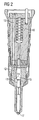
- FIGURE shows a schematic sectional view of a section of a high-pressure resistant component 1 of a fuel injection system, such as an injection nozzle, an injector body, a Schmiederails, a welding rail, a displacer unit of a common rail high pressure pump or the high pressure region of a common rail high pressure pump.
- a fuel injection system such as an injection nozzle, an injector body, a Schmiederails, a welding rail, a displacer unit of a common rail high pressure pump or the high pressure region of a common rail high pressure pump.
- the component 1 has a main channel and a branch channel, which are formed in the form of a first cylindrical bore 2 and a second cylindrical bore 3.
- the second bore 3 branches off in the region of the inner wall 4 of the first bore 2 from the first bore 2.
- a peripheral edge 5 is formed in the component 1, which is sharp-edged after production of the holes 2 and 3.
- the longitudinal axes L, 1 of the two holes 2 and 3 extend in the illustrated preferred embodiment at a right angle to each other and the resulting branching area is T-shaped.
- the inner walls 4, 6 and the edge 5 are reworked by a grinding process or honing process.
- compressive stresses are introduced into the surfaces of the inner walls 4, 6 and the edge 5, which are directed counter to the fluid, in particular fuel, which is guided later in the bores 2, 3 under high pressure.
- These compressive stresses have in the region of the surface of the inner walls 4, 6 values up to 1000 N / mm 2 ; in a depth of about 0.1 mm below the surface of the inner walls 4, 6, these compressive stresses are still at 700 N / mm 2 .
- the edge 5 is rounded hydro-erosively to increase the high-pressure resistance of the component 1.
- an offset with grinding wheels 7 liquid 8 preferably a highly viscous lubricating oil, introduced by means of a feed pump, not shown in the first bore 2 and guided across the edge 5 to be rounded.
- transverse is meant here any flow at an angle to the peripheral edge.
- this ensures that the portion of the edge 5, which faces away from the inlet of the liquid 8 with the grinding bodies 7 or facing the closing element 9 - referred to below as the counter edge 11 - has a more advantageous flow around than without the closure element 9. Accordingly, good rounding results are achieved.
- the designated as the inflow edge 10 portion of the edge 5, which faces the inlet of the liquid 8 with the grinding wheels 7 and the end element 9 is still sufficiently rounded.
- the maximum removal of material by the hydro-erosive rounding is in the range of 10 ⁇ m to 50 ⁇ m, preferably 20 ⁇ m to 40 ⁇ m.
- an increase in the flow velocity is associated with an increase in the erosive effect of the liquid 8 mixed with the abrasive bodies 7.
- the hydro-erosive Ver round is carried out at pressures in the range of about 10 bar to 500 bar.
- the bore 2 has a diameter D which is slightly larger than the diameter d of the branching bore 3.
- the diameter D, d of the holes are in the usual manner in a range of 0.5 mm to 10 mm, preferably in the range of about 2 mm to 4 mm.
Landscapes
- Engineering & Computer Science (AREA)
- Mechanical Engineering (AREA)
- Fuel-Injection Apparatus (AREA)
Claims (6)
- Procédé d'usinage d'une arête d'une pièce résistante aux pressions élevées, en particulier d'une arête d'une intersection entre des perçages dans une pièce résistante aux pressions élevées d'un dispositif d'injection de carburant, dans lequel procédé l'arête est arrondie par hydro-érosion au cours d'une étape d'usinage,
caractérisé en ce que,
avant l'étape d'usinage par hydro-érosion de l'arrondi, l'arête (5) et les surfaces (4, 6) adjacentes à l'arête (5) de la pièce (1) résistante aux pressions élevées sont soumises respectivement à des contraintes de pression dans la zone de leur surface au moyen d'un procédé de meulage et/ou de rodage. - Procédé selon la revendication 1,
caractérisé en ce que l'arête (5) et les surfaces (4, 6) adjacentes à l'arête (5), de préférence des surfaces cylindriques des perçages (2, 3), de la pièce (1) résistante aux pressions élevées sont soumises dans la zone de leur surface respectivement à des contraintes de pression dans une plage de 500 N/mm2 à 1 500 N/mm2, au moyen du procédé de meulage et/ou de rodage. - Procédé selon la revendication 1 ou 2,
caractérisé en ce que l'arête (5) est arrondie au cours de l'étape d'arrondissage par hydro-érosion et, de ce fait, l'enlèvement de matière se situe au maximum dans une plage de 10 µm à 50 µm. - Procédé d'arrondissage par hydro-érosion d'une arête d'une pièce résistante aux pressions élevées, en particulier d'une arête d'une intersection entre des perçages dans une pièce résistante aux pressions élevées d'un dispositif d'injection de carburant, dans lequel procédé un liquide chargé de particules abrasives est guidé transversalement sur l'arête à arrondir dans une zone d'un premier perçage continu bifurquant dans un deuxième perçage de dérivation, étant utilisé comme procédé selon les revendications 1 à 3,
caractérisé en ce que pour faire varier la direction du liquide (8) chargé de particules abrasives (7) depuis le premier perçage (2) continu vers le deuxième perçage (3) de dérivation, le premier perçage (2) est obturé par un élément d'obturation (9) en aval du deuxième perçage (3) de dérivation, par référence à la direction d'écoulement principale du liquide (8) chargé de particules abrasives (7). - Procédé selon la revendication 4,
caractérisé en ce que le premier perçage (2) continu est obturé par un élément d'obturation (9) à une distance (a) d'environ 0,5 mm à 10 mm par rapport à l'arête (5), en aval du deuxième perçage (3) de dérivation, par référence à la direction d'écoulement principale du liquide (8) chargé de particules abrasives (7). - Procédé selon la revendication 4 ou 5,
caractérisé en ce que l'on fait varier au moins une fois, de préférence plusieurs fois, la direction d'écoulement principale (S) du liquide (8) chargé de particules abrasives (7) dans le premier perçage (2), et, de manière correspondante, on change la position de l'élément d'obturation (9).
Applications Claiming Priority (3)
| Application Number | Priority Date | Filing Date | Title |
|---|---|---|---|
| DE10260302A DE10260302A1 (de) | 2002-12-20 | 2002-12-20 | Verfahren zum Bearbeiten einer Kante eines hochdruckfesten Bauteils , insbesondere zum hydro-erosiven Verrunden einer Kante sowie und Vorrichtung hierzu |
| DE10260302 | 2002-12-20 | ||
| PCT/DE2003/004063 WO2004056530A2 (fr) | 2002-12-20 | 2003-12-10 | Procedes d'usinage d'une arete d'un composant resistant aux pressions elevees, notamment procedes d'arrondissage hydro-erosif d'une arete, et dispositif correspondant |
Publications (3)
| Publication Number | Publication Date |
|---|---|
| EP1572420A2 EP1572420A2 (fr) | 2005-09-14 |
| EP1572420B1 true EP1572420B1 (fr) | 2008-02-27 |
| EP1572420B8 EP1572420B8 (fr) | 2008-05-07 |
Family
ID=32519258
Family Applications (1)
| Application Number | Title | Priority Date | Filing Date |
|---|---|---|---|
| EP03788869A Expired - Lifetime EP1572420B8 (fr) | 2002-12-20 | 2003-12-10 | Procedes d'usinage d'une arete d'un composant resistant aux pressions elevees, notamment procedes d'arrondissage hydro-erosif d'une arete, et dispositif correspondant |
Country Status (5)
| Country | Link |
|---|---|
| US (1) | US7637800B2 (fr) |
| EP (1) | EP1572420B8 (fr) |
| JP (1) | JP2006509644A (fr) |
| DE (2) | DE10260302A1 (fr) |
| WO (1) | WO2004056530A2 (fr) |
Cited By (1)
| Publication number | Priority date | Publication date | Assignee | Title |
|---|---|---|---|---|
| DE102010007704A1 (de) | 2010-02-11 | 2011-08-11 | Daimler AG, 70327 | Vorrichtung zum Bearbeiten eines rotationssymmetrischen Hohlraumes eines druckfesten Bauteiles |
Families Citing this family (7)
| Publication number | Priority date | Publication date | Assignee | Title |
|---|---|---|---|---|
| DE102005026511A1 (de) * | 2005-06-09 | 2006-12-14 | Robert Bosch Gmbh | Ventil, insbesondere zur Verwendung als Saugventil auf der Saugseite von Kraftstoffeinspritzsystemen |
| JP4484227B2 (ja) * | 2006-10-02 | 2010-06-16 | ボッシュ株式会社 | コモンレール |
| US8187056B2 (en) * | 2006-12-14 | 2012-05-29 | Flow International Corporation | Process and apparatus for surface-finishing |
| US9676045B2 (en) | 2011-02-28 | 2017-06-13 | Corning Optical Communications Rf Llc | Electrodes, components, apparatuses, and methods for burr-free or substantially burr-free electrochemical machining |
| DE102015009153A1 (de) * | 2015-07-14 | 2017-01-19 | Liebherr-Aerospace Lindenberg Gmbh | Herstellungsverfahren eines Leitungsbauteils |
| US10646977B2 (en) | 2016-06-17 | 2020-05-12 | United Technologies Corporation | Abrasive flow machining method |
| WO2025144796A1 (fr) * | 2023-12-26 | 2025-07-03 | Vaya Space, Inc. | Procédé et appareil de finition d'écoulement abrasif à basse pression |
Family Cites Families (10)
| Publication number | Priority date | Publication date | Assignee | Title |
|---|---|---|---|---|
| US5054247A (en) * | 1986-03-21 | 1991-10-08 | Extrude Hone Corporation | Method of controlling flow resistance in fluid orifice manufacture |
| US5076027A (en) * | 1987-12-17 | 1991-12-31 | Extrude Hone Corporation | Process for abrasive flow machining using multiple cylinders |
| US5195276A (en) * | 1991-02-15 | 1993-03-23 | Outboard Marine Corporation | Apparatus and method for flushing a casting |
| DE19757117A1 (de) * | 1997-12-20 | 1999-06-24 | Bosch Gmbh Robert | Verfahren zur Herstellung eines Ventilsitzkörpers für ein Brennstoffeinspritzventil und Brennstoffeinspritzventil |
| DE19902423A1 (de) * | 1999-01-22 | 2000-08-03 | Bosch Gmbh Robert | Vorrichtung und Verfahren zur Bearbeitung einer Innenoberfläche |
| DE19953131A1 (de) * | 1999-11-04 | 2001-08-02 | Bosch Gmbh Robert | Verfahren und Vorrichtung zum Kantenverrunden |
| US6503126B1 (en) * | 2000-09-12 | 2003-01-07 | Extrude Hone Corporation | Method and apparatus for abrading the region of intersection between a branch outlet and a passageway in a body |
| JP2002103200A (ja) * | 2000-09-28 | 2002-04-09 | Tooyoo:Kk | ホーニング工具 |
| US6739956B2 (en) * | 2001-10-30 | 2004-05-25 | Valiant Corporation | Apparatus for cleaning engine block passages |
| JP3681714B2 (ja) * | 2002-06-18 | 2005-08-10 | 株式会社不二精機製造所 | 部材内部の長孔交差部のブラスト加工方法 |
-
2002
- 2002-12-20 DE DE10260302A patent/DE10260302A1/de not_active Ceased
-
2003
- 2003-12-10 EP EP03788869A patent/EP1572420B8/fr not_active Expired - Lifetime
- 2003-12-10 WO PCT/DE2003/004063 patent/WO2004056530A2/fr not_active Ceased
- 2003-12-10 JP JP2004561032A patent/JP2006509644A/ja not_active Abandoned
- 2003-12-10 DE DE50309277T patent/DE50309277D1/de not_active Expired - Lifetime
-
2005
- 2005-06-20 US US11/156,984 patent/US7637800B2/en not_active Expired - Lifetime
Cited By (1)
| Publication number | Priority date | Publication date | Assignee | Title |
|---|---|---|---|---|
| DE102010007704A1 (de) | 2010-02-11 | 2011-08-11 | Daimler AG, 70327 | Vorrichtung zum Bearbeiten eines rotationssymmetrischen Hohlraumes eines druckfesten Bauteiles |
Also Published As
| Publication number | Publication date |
|---|---|
| EP1572420B8 (fr) | 2008-05-07 |
| JP2006509644A (ja) | 2006-03-23 |
| WO2004056530A3 (fr) | 2004-08-26 |
| DE50309277D1 (de) | 2008-04-10 |
| US20060010688A1 (en) | 2006-01-19 |
| US7637800B2 (en) | 2009-12-29 |
| WO2004056530A2 (fr) | 2004-07-08 |
| WO2004056530A8 (fr) | 2004-10-21 |
| EP1572420A2 (fr) | 2005-09-14 |
| DE10260302A1 (de) | 2004-07-15 |
Similar Documents
| Publication | Publication Date | Title |
|---|---|---|
| WO2001053694A1 (fr) | Procede permettant de realiser un orifice traversant dans un accumulateur haute pression de carburant et dispositif permettant de mettre en oeuvre ce procede | |
| DE10225304B4 (de) | Vorrichtung zum Bearbeiten von Bauteilkonturen | |
| WO2010086330A1 (fr) | Géométrie permettant d'augmenter la résistance au niveau d'intersections de trous dans la zone haute pression | |
| WO2017174542A1 (fr) | Outil d'usinage par enlèvement de copeaux pour ébavurer des alésages | |
| WO2004056530A2 (fr) | Procedes d'usinage d'une arete d'un composant resistant aux pressions elevees, notamment procedes d'arrondissage hydro-erosif d'une arete, et dispositif correspondant | |
| EP1517766B1 (fr) | Procede permettant d'arrondir, par erosion hydraulique, un bord d'un composant et utilisation de ce procede | |
| WO2006136470A1 (fr) | Tuyere et procede pour façonner une cavite interieure dans une piece d'usinage | |
| DE4437927C2 (de) | Magnetventilgesteuerte Kraftstoffeinspritzvorrichtung mit einer Einspritzdüse zur Kraftstoffeinspritzung in den Brennraum einer Dieselbrennkraftmaschine | |
| EP1180068B1 (fr) | Procede et dispositif pour arrondir des aretes | |
| EP3085492B1 (fr) | Outil de rectification | |
| CH717897A2 (de) | Ventileinrichtung für ein gesteuertes Durchlassen eines Mediums insbesondere im Hochdruckbereich. | |
| DE10214404A1 (de) | Bauelement, insbesondere Gehäuse einer Hochdruck-Kraftstoffpumpe, sowie Verfahren zu seiner Herstellung | |
| DE10230170B3 (de) | Verfahren und Vorrichtung zum hydro-erosiven Verrunden einer Kante eines Bauteils | |
| WO2005054522A1 (fr) | Procede pour le durcissement selectif de surfaces d'etancheite | |
| DE102011076649B4 (de) | Schleifstift zum Schleifen einer Innenoberfläche eines Hohlraumes | |
| WO2017220240A1 (fr) | Pompe à carburant haute pression comprenant un carter et procédé d'usinage de conduits d'un carter d'une pompe à carburant haute pression | |
| DE102008044022A1 (de) | Verfahren zum Bearbeiten einer Fluidvorrichtung mit zwei sich schräg miteinander schneidenden Strömungsdurchgängen | |
| DE10103435C2 (de) | Schleifwerkzeug und Verfahren zu dessen Herstellung | |
| DE102008015284B4 (de) | Verfahren zum Ausbilden einer Hochdruckkanalanordnung in einem Körper | |
| EP1570950B1 (fr) | Procédé et dispositif pour usiner une pièce | |
| DE102018207717A1 (de) | Vorrichtung zur Erzeugung eines Hochdruckfluidstrahls | |
| DE102016122785B4 (de) | Verfahren zum Herstellen einer Brennstoff- oder Hydraulikmittelleiteinheit mittels kombinatorischem ECM-Bearbeitens und Laserbohrens | |
| DE102007016116B4 (de) | Verfahren zum Ausbilden einer Hochdruckkanalanordnung in einem Körper | |
| DE102022207928A1 (de) | Welle für ein Fahrzeuggetriebe | |
| CH711662A1 (de) | Herstellungsverfahren für Steuerplatten einer hydraulischen Maschine. |
Legal Events
| Date | Code | Title | Description |
|---|---|---|---|
| PUAI | Public reference made under article 153(3) epc to a published international application that has entered the european phase |
Free format text: ORIGINAL CODE: 0009012 |
|
| 17P | Request for examination filed |
Effective date: 20050525 |
|
| AK | Designated contracting states |
Kind code of ref document: A2 Designated state(s): AT BE BG CH CY CZ DE DK EE ES FI FR GB GR HU IE IT LI LU MC NL PT RO SE SI SK TR |
|
| RBV | Designated contracting states (corrected) |
Designated state(s): DE FR GB IT |
|
| 17Q | First examination report despatched |
Effective date: 20051028 |
|
| RAP1 | Party data changed (applicant data changed or rights of an application transferred) |
Owner name: SIEMENS AKTIENGESELLSCHAFT |
|
| GRAP | Despatch of communication of intention to grant a patent |
Free format text: ORIGINAL CODE: EPIDOSNIGR1 |
|
| GRAC | Information related to communication of intention to grant a patent modified |
Free format text: ORIGINAL CODE: EPIDOSCIGR1 |
|
| GRAS | Grant fee paid |
Free format text: ORIGINAL CODE: EPIDOSNIGR3 |
|
| GRAA | (expected) grant |
Free format text: ORIGINAL CODE: 0009210 |
|
| RAP1 | Party data changed (applicant data changed or rights of an application transferred) |
Owner name: SIEMENS VDO AUTOMOTIVE AG |
|
| AK | Designated contracting states |
Kind code of ref document: B1 Designated state(s): DE FR GB IT |
|
| REG | Reference to a national code |
Ref country code: GB Ref legal event code: FG4D Free format text: NOT ENGLISH |
|
| RAP2 | Party data changed (patent owner data changed or rights of a patent transferred) |
Owner name: VDO AUTOMOTIVE AG |
|
| REF | Corresponds to: |
Ref document number: 50309277 Country of ref document: DE Date of ref document: 20080410 Kind code of ref document: P |
|
| RAP2 | Party data changed (patent owner data changed or rights of a patent transferred) |
Owner name: CONTINENTAL AUTOMOTIVE GMBH |
|
| ET | Fr: translation filed | ||
| PLBE | No opposition filed within time limit |
Free format text: ORIGINAL CODE: 0009261 |
|
| STAA | Information on the status of an ep patent application or granted ep patent |
Free format text: STATUS: NO OPPOSITION FILED WITHIN TIME LIMIT |
|
| 26N | No opposition filed |
Effective date: 20081128 |
|
| GBPC | Gb: european patent ceased through non-payment of renewal fee |
Effective date: 20081210 |
|
| PG25 | Lapsed in a contracting state [announced via postgrant information from national office to epo] |
Ref country code: IT Free format text: LAPSE BECAUSE OF FAILURE TO SUBMIT A TRANSLATION OF THE DESCRIPTION OR TO PAY THE FEE WITHIN THE PRESCRIBED TIME-LIMIT Effective date: 20080227 |
|
| PG25 | Lapsed in a contracting state [announced via postgrant information from national office to epo] |
Ref country code: GB Free format text: LAPSE BECAUSE OF NON-PAYMENT OF DUE FEES Effective date: 20081210 |
|
| REG | Reference to a national code |
Ref country code: FR Ref legal event code: TP Owner name: CONTINENTAL AUTOMOTIVE GMBH, DE Effective date: 20111104 Ref country code: FR Ref legal event code: CD Owner name: CONTINENTAL AUTOMOTIVE GMBH, DE Effective date: 20111104 |
|
| REG | Reference to a national code |
Ref country code: FR Ref legal event code: PLFP Year of fee payment: 13 |
|
| REG | Reference to a national code |
Ref country code: FR Ref legal event code: PLFP Year of fee payment: 14 |
|
| REG | Reference to a national code |
Ref country code: FR Ref legal event code: PLFP Year of fee payment: 15 |
|
| REG | Reference to a national code |
Ref country code: DE Ref legal event code: R084 Ref document number: 50309277 Country of ref document: DE |
|
| REG | Reference to a national code |
Ref country code: DE Ref legal event code: R081 Ref document number: 50309277 Country of ref document: DE Owner name: VITESCO TECHNOLOGIES GMBH, DE Free format text: FORMER OWNER: CONTINENTAL AUTOMOTIVE GMBH, 30165 HANNOVER, DE |
|
| PGFP | Annual fee paid to national office [announced via postgrant information from national office to epo] |
Ref country code: FR Payment date: 20201223 Year of fee payment: 18 |
|
| PGFP | Annual fee paid to national office [announced via postgrant information from national office to epo] |
Ref country code: DE Payment date: 20201231 Year of fee payment: 18 |
|
| REG | Reference to a national code |
Ref country code: DE Ref legal event code: R081 Ref document number: 50309277 Country of ref document: DE Owner name: VITESCO TECHNOLOGIES GMBH, DE Free format text: FORMER OWNER: VITESCO TECHNOLOGIES GMBH, 30165 HANNOVER, DE |
|
| REG | Reference to a national code |
Ref country code: DE Ref legal event code: R119 Ref document number: 50309277 Country of ref document: DE |
|
| PG25 | Lapsed in a contracting state [announced via postgrant information from national office to epo] |
Ref country code: DE Free format text: LAPSE BECAUSE OF NON-PAYMENT OF DUE FEES Effective date: 20220701 |
|
| PG25 | Lapsed in a contracting state [announced via postgrant information from national office to epo] |
Ref country code: FR Free format text: LAPSE BECAUSE OF NON-PAYMENT OF DUE FEES Effective date: 20211231 |