EP1573176B1 - Moteur a combustion interne comportant un dispositif de reglage hydraulique de l'angle de rotation de l'arbre a cames par rapport au vilebrequin ainsi qu'une pompe a vide destinee a un servorecepteur notamment con u pour un amplificateur de freinage - Google Patents
Moteur a combustion interne comportant un dispositif de reglage hydraulique de l'angle de rotation de l'arbre a cames par rapport au vilebrequin ainsi qu'une pompe a vide destinee a un servorecepteur notamment con u pour un amplificateur de freinage Download PDFInfo
- Publication number
- EP1573176B1 EP1573176B1 EP03767676A EP03767676A EP1573176B1 EP 1573176 B1 EP1573176 B1 EP 1573176B1 EP 03767676 A EP03767676 A EP 03767676A EP 03767676 A EP03767676 A EP 03767676A EP 1573176 B1 EP1573176 B1 EP 1573176B1
- Authority
- EP
- European Patent Office
- Prior art keywords
- vacuum pump
- camshaft
- internal combustion
- combustion engine
- axial
- Prior art date
- Legal status (The legal status is an assumption and is not a legal conclusion. Google has not performed a legal analysis and makes no representation as to the accuracy of the status listed.)
- Expired - Lifetime
Links
- 238000002485 combustion reaction Methods 0.000 title claims description 47
- 230000008878 coupling Effects 0.000 claims description 20
- 238000010168 coupling process Methods 0.000 claims description 20
- 238000005859 coupling reaction Methods 0.000 claims description 20
- 239000010687 lubricating oil Substances 0.000 claims description 20
- 238000005461 lubrication Methods 0.000 claims description 8
- 239000003921 oil Substances 0.000 claims description 8
- 230000000295 complement effect Effects 0.000 claims description 4
- 230000005540 biological transmission Effects 0.000 description 3
- 230000015572 biosynthetic process Effects 0.000 description 1
- 238000005516 engineering process Methods 0.000 description 1
Images
Classifications
-
- B—PERFORMING OPERATIONS; TRANSPORTING
- B60—VEHICLES IN GENERAL
- B60T—VEHICLE BRAKE CONTROL SYSTEMS OR PARTS THEREOF; BRAKE CONTROL SYSTEMS OR PARTS THEREOF, IN GENERAL; ARRANGEMENT OF BRAKING ELEMENTS ON VEHICLES IN GENERAL; PORTABLE DEVICES FOR PREVENTING UNWANTED MOVEMENT OF VEHICLES; VEHICLE MODIFICATIONS TO FACILITATE COOLING OF BRAKES
- B60T17/00—Component parts, details, or accessories of power brake systems not covered by groups B60T8/00, B60T13/00 or B60T15/00, or presenting other characteristic features
- B60T17/02—Arrangements of pumps or compressors, or control devices therefor
-
- F—MECHANICAL ENGINEERING; LIGHTING; HEATING; WEAPONS; BLASTING
- F01—MACHINES OR ENGINES IN GENERAL; ENGINE PLANTS IN GENERAL; STEAM ENGINES
- F01L—CYCLICALLY OPERATING VALVES FOR MACHINES OR ENGINES
- F01L1/00—Valve-gear or valve arrangements, e.g. lift-valve gear
- F01L1/02—Valve drive
- F01L1/04—Valve drive by means of cams, camshafts, cam discs, eccentrics or the like
- F01L1/047—Camshafts
- F01L1/053—Camshafts overhead type
-
- F—MECHANICAL ENGINEERING; LIGHTING; HEATING; WEAPONS; BLASTING
- F01—MACHINES OR ENGINES IN GENERAL; ENGINE PLANTS IN GENERAL; STEAM ENGINES
- F01L—CYCLICALLY OPERATING VALVES FOR MACHINES OR ENGINES
- F01L1/00—Valve-gear or valve arrangements, e.g. lift-valve gear
- F01L1/34—Valve-gear or valve arrangements, e.g. lift-valve gear characterised by the provision of means for changing the timing of the valves without changing the duration of opening and without affecting the magnitude of the valve lift
-
- F—MECHANICAL ENGINEERING; LIGHTING; HEATING; WEAPONS; BLASTING
- F01—MACHINES OR ENGINES IN GENERAL; ENGINE PLANTS IN GENERAL; STEAM ENGINES
- F01L—CYCLICALLY OPERATING VALVES FOR MACHINES OR ENGINES
- F01L1/00—Valve-gear or valve arrangements, e.g. lift-valve gear
- F01L1/34—Valve-gear or valve arrangements, e.g. lift-valve gear characterised by the provision of means for changing the timing of the valves without changing the duration of opening and without affecting the magnitude of the valve lift
- F01L1/344—Valve-gear or valve arrangements, e.g. lift-valve gear characterised by the provision of means for changing the timing of the valves without changing the duration of opening and without affecting the magnitude of the valve lift changing the angular relationship between crankshaft and camshaft, e.g. using helicoidal gear
- F01L1/3442—Valve-gear or valve arrangements, e.g. lift-valve gear characterised by the provision of means for changing the timing of the valves without changing the duration of opening and without affecting the magnitude of the valve lift changing the angular relationship between crankshaft and camshaft, e.g. using helicoidal gear using hydraulic chambers with variable volume to transmit the rotating force
-
- F—MECHANICAL ENGINEERING; LIGHTING; HEATING; WEAPONS; BLASTING
- F01—MACHINES OR ENGINES IN GENERAL; ENGINE PLANTS IN GENERAL; STEAM ENGINES
- F01L—CYCLICALLY OPERATING VALVES FOR MACHINES OR ENGINES
- F01L1/00—Valve-gear or valve arrangements, e.g. lift-valve gear
- F01L1/46—Component parts, details, or accessories, not provided for in preceding subgroups
Definitions
- the invention relates to an internal combustion engine having a device for the hydraulic rotational angle adjustment of its camshaft with respect to its crankshaft and with a vacuum pump for a servo load, in particular for a brake booster, according to the preamble forming features of claim 1.
- the usually used devices for adjusting the rotational angle are in principle designed as a hydraulic actuator, which is either as a so-called Axialkolbenversteller or similar to those from EP 0 818 609 B1 known device is designed as a so-called Rotationskolbenversteller.
- This device is arranged on the drive-side end of the camshaft mounted in a plurality of radial bearings in the cylinder head of the internal combustion engine and consists essentially of a standing with the crankshaft of the internal combustion engine in drive connection drive unit and a rotatably connected to the camshaft of the engine output unit.
- the output unit is concretely designed as an impeller and fixed by an axial central screw on the camshaft, while the drive unit as the output unit enclosing hollow cylinder is formed, which is closed by two axial side walls pressure medium tight.
- the drive unit as the output unit enclosing hollow cylinder is formed, which is closed by two axial side walls pressure medium tight.
- the vacuum pumps commonly used in internal combustion engines for a servo load are usually designed as a vane pump, as for example from the DE 85 18 157 U1 evident.
- This vacuum pump is arranged on a common longitudinal axis with the camshaft on the cylinder head of the internal combustion engine and consists essentially of a flanged to the cylinder head cover of the engine housing with a bearing neck and arranged in the housing rotor with a drive shaft, in which in the cylinder head of the internal combustion engine protruding bearing neck of the housing is rotatably mounted.
- the camshaft still has an axial lubricating oil channel leading to its end face, which is connected on the one hand via a coupling tube to an axial lubricating oil collecting space in the drive shaft of the vacuum pump and on the other hand to the lubricating oil circuit of the internal combustion engine, so that the vacuum pump is simultaneously lubricated with the lubricating oil of the internal combustion engine ,
- the vacuum pump in such a way that it can be suitably integrated into the primary or secondary drive of the internal combustion engine and in the lubricating oil circuit, so that in any case with a considerable additional expense for the internal combustion engine is to be expected.
- the invention is therefore based on the object, an internal combustion engine with a device for adjusting the rotational angle of its camshaft with respect to its crankshaft and with a vacuum pump for a servo consumer, in particular for a brake booster, to be designed in which, despite a device attached to the drive end of its camshaft Rotation angle adjustment in a usually arranged on the cylinder head of the internal combustion engine vacuum pump with a cost-effective drive and easy lubrication is used.
- this object is achieved in an internal combustion engine according to the preamble of claim 1 such that the vacuum pump disposed axially relative to the device for adjusting the rotational angle on a common longitudinal axis with the device on the cylinder head of the internal combustion engine and the device is formed with additional coupling elements, via which the drive shaft the vacuum pump is in drive connection with the device, wherein the lubrication of the vacuum pump via a arranged in its drive shaft and the device projecting, centric connecting pipe with the device as the pressure medium supplied lubricating oil of the internal combustion engine.
- the coupling arranged on the drive shaft of the vacuum pump is preferably formed by two radial teeth arranged coaxially on the device-facing end face, while the additional coupling elements on the device are preferably designed as two radial slots complementary to the radial teeth on the drive shaft. It has proven to be particularly advantageous to form the two radial teeth as rectangular webs protruding axially from the end face of the drive shaft facing the device, which are offset by 180 ° from one another or are arranged directly opposite one another and are formed integrally with the drive shaft.
- the opposite side of the device for adjusting the rotational angle is then designed in a further embodiment of the inventive engine designed such that the axial central screw of the device with its pointing to the vacuum pump screw head is sunk in a diameter extension of their screw hole in the output unit of the device, wherein the camshaft side facing away from the Device has an axial through hole with the same diameter as the diameter extension of the screw hole in the drive unit of the device through which the axial central screw is passed.
- this diameter extension for the screw head of the central screw in the output unit is connected to one of the oil passages for supplying pressure medium of the device and oil-tight closed by a in the same large through hole in the camshaft side facing away from the device screwed lid.
- the substantially disc-shaped lid is formed on its closure side with a coaxial annular projection with an external thread whose length corresponds approximately to the thickness of the formed in its through hole with an internal thread camshaft side facing away from the device.
- This cover then has the two radial slots for the coupling of the vacuum pump formed by two radial teeth on the end face of the drive shaft, which are preferably formed as two base grooves extending from the edge of the cover and offset by 180 ° from each other or just opposite one another the vacuum pump is driven by the rotational angle adjustment device.
- the connecting tube of the vacuum pump to the device for adjusting the rotational angle sealingly received through which a subset of the guided in the diameter extension for the screw head of the central screw pressure medium of the device is passed leak-free as lubricating oil in the vacuum pump.
- the two radial slots for the coupling of the vacuum pump formed by two radial teeth on the end face of the drive shaft are preferably designed as basic grooves incorporated directly into the side wall of the device facing away from the camshaft, that of the diameter enlargement for the screw head of the central screw leading through hole in the side wall of the device and also offset by 180 ° to each other or are arranged just opposite each other.
- the connecting pipe of the vacuum pump to the device is sealingly received, through which as well as in the first embodiment, a subset of the pressure medium into the device leak-free as lubricating oil in de vacuum pump is forwarded.
- the inventively embodied internal combustion engine with a device for the hydraulic rotation angle adjustment of its camshaft with respect to its crankshaft and with a vacuum pump for a servo load, in particular for a brake booster thus has the advantage over the known from the prior art, the advantage that it by creating a cost-effective drive connection between the device for adjusting the rotational angle and the vacuum pump via a positive coupling and by the simultaneous use of a subset of the pressure medium of the device as a lubricating oil for the vacuum pump via a simple connecting pipe between the device and the vacuum pump is now possible, despite the arranged at the drive end of the camshaft rotational angle adjustment device to arrange the vacuum pump usually on a common longitudinal axis with the camshaft on the cylinder head cover of the engine.
- the vacuum pump does not have to be adapted to a different drive and / or a different type of lubrication, either in terms of its design or in its arrangement, so that the additional expenditure required for the internal combustion engine can be saved.
- the connecting tube between the vacuum pump and the device for rotational angle adjustment and forming the diameter enlargement in the device occlusive cover without centric axial bore or formation of the through hole in the central screw as a blind hole, however, it is also possible only the drive of the vacuum pump in accordance with the invention by the To realize device for the rotation angle adjustment and to provide a separate lubricating oil supply for the vacuum pump.
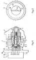
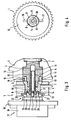
- Figures 1 and 3 each show a partial view of an internal combustion engine having both a device 1 for the hydraulic rotation angle adjustment of its camshaft 3 relative to its crankshaft and a vacuum pump 17 for a servo consumer, in particular for a brake booster of a motor vehicle.
- the trained in principle as a hydraulic actuator device 1 for hydraulic rotation angle adjustment is arranged at the drive end 2 of the stored in several radial bearings 4 in the cylinder head 5 of the engine camshaft 3 and substantially from one with the crankshaft a traction means drivingly connected drive unit 6 and from a non-rotatably connected to the camshaft 3 of the internal combustion engine output unit 7 consists.
- the output unit 7 of the device 1 is secured by an axial central screw 8 at the drive end 2 of the camshaft 3, while the drive unit 6 is formed by a the output unit 7 enclosing hollow cylinder by two axial side walls 12, 13 is pressure-tight sealed. About at least two formed within the device 1, alternately or simultaneously acted upon by a hydraulic pressure medium pressure chambers is then the drive unit 6 to the output unit 7 in power transmission connection, wherein as a hydraulic pressure means for the device 1 from one of the radial bearing 4 of the camshaft extracted lubricating oil of the internal combustion engine is used, which is supplied via radial and axial oil passages 15, 16 in the camshaft 3 of the device 1.
- Vacuum pump 17 arranged axially relative to the device 1 on a common longitudinal axis with this and the device 1 is formed with additional coupling elements, via which the drive shaft 20 of the vacuum pump 17 is now in driving connection with the device 1.
- the lubrication of the vacuum pump 17 is effected according to the invention via a likewise visible in Figures 1 and 3, arranged in the drive shaft 20 of the vacuum pump 17 connecting tube 23 which projects into the device 1 and a subset of the device 1 as a pressure medium supplied lubricating oil of the internal combustion engine the vacuum pump 17 forwards.
- the opposite side of the device 1 for adjusting the rotational angle is designed such that the axial central screw 8 of the device 1 is recessed with its screw head 9 in a diameter extension 11 of its screw hole 10 in the drive unit 7 of the device 1 and the side facing away from the camshaft 12 of the device 1 has an axial through hole 14 of the same diameter through which the axial central screw 8 is passed.
- this diameter extension 11 is clearly visible for the screw head 9 of the central screw 8 connected to one of the axial oil passages 16 to the pressure medium supply of the device 1 and through a into the through hole 14 in the camshaft facing away Side wall 12 of the device 1 screw-lid 28 oil-tightly closed.
- This cover 28 on the camshaft side wall 12 facing away from the device 1 then has the two radial slots 26, 27 for the coupling 22 of the vacuum pump 17, which, as can be seen in Figure 2, as two outgoing from the edge of the lid 28 and just opposite arranged Grundnuten are formed.
- the connecting tube 23 of the vacuum pump 17 is sealingly received to the device 1, through which a subset of the pressure in the diameter extension 11 for the screw head 9 of the central screw 8 pressure medium of the device 1 as lubricating oil in the vacuum pump 17th is forwarded.
- the diameter extension 11 for the screw head 9 of the central screw 8 clearly not connected to the pressure medium supply of the device 1, as for the pressure medium supply of the device 1 is a continuous longitudinal bore 30 in the axial central screw 8 is provided. Since therefore also no cover 28 for closing the diameter extension 11 or the through hole 14 in the camshaft side wall 12 of the device 1 is necessary, the radial slots 26, 27 for the clutch 22 of the vacuum pump 17 in this embodiment as directly in the camshaft side facing away from the wall 12th
- the device 1 incorporated basic grooves formed, which, as Figure 4 clearly shows, emanating from the through hole 14 to the diameter extension 11 in the drive unit 7 and are arranged just opposite one another.
- the connecting tube 23 of the vacuum pump is then sealed to the device 1, through which a subset of the pressure medium conducted into the device 1 is forwarded as a lubricating oil into the vacuum pump 17.
Landscapes
- Engineering & Computer Science (AREA)
- Mechanical Engineering (AREA)
- General Engineering & Computer Science (AREA)
- Transportation (AREA)
- Valve Device For Special Equipments (AREA)
- Valve-Gear Or Valve Arrangements (AREA)
- Lubrication Of Internal Combustion Engines (AREA)
Claims (7)
- Moteur à combustion interne comportant un dispositif de réglage hydraulique de l'angle de rotation de l'arbre à cames par rapport au vilebrequin ainsi qu'une pompe à vide destinée à un servorécepteur, notamment à un amplificateur de freinage, avec les caractéristiques suivantes :- le dispositif (1) de réglage hydraulique de l'angle de rotation est disposé à l'extrémité (2) côté entraînement de l'arbre à cames (3) monté dans plusieurs paliers radiaux (4) dans la culasse (5) du moteur à combustion interne et est réalisé dans son principe sous forme de servo-entraînement hydraulique,- le dispositif (1) est constitué pour l'essentiel d'une unité menante (6) se trouvant en liaison d'entraînement avec le vilebrequin du moteur à combustion interne et d'une unité menée (7) liée en rotation à l'arbre à cames (3) du moteur à combustion interne,- l'unité menée (7) est fixée par une vis centrale axiale (8) sur l'arbre à cames (3) et l'unité menante (6) est réalisée sous forme de cylindre creux qui entoure l'unité menée (7) et est fermé en étanchéité au fluide sous pression par deux parois latérales axiales (12, 13),- l'unité menante (6) se trouve en liaison de transmission de force avec l'unité menée (7) du dispositif (1) par l'intermédiaire d'au moins deux chambres de pression formées à l'intérieur du dispositif (1) et alimentées alternativement ou simultanément en fluide hydraulique sous pression,- comme fluide hydraulique sous pression pour le dispositif (1), on utilise l'huile de lubrification du moteur à combustion interne, prélevée d'un des paliers radiaux (4) de l'arbre à cames (3), qui est apportée au dispositif (1) par l'intermédiaire de canaux d'huile radiaux et axiaux (15, 16) dans l'arbre à cames (3),- la pompe à vide (17) pour le servorécepteur est réalisée sous forme de pompe rotative à ailettes et est constituée pour l'essentiel d'un carter (19) flasqué sur le couvercle de culasse (18) du moteur à combustion interne, et d'un rotor disposé dans ce carter et pourvu d'un arbre d'entraînement (20),- la transmission du mouvement de rotation de l'arbre à cames (3) à la pompe à vide (17), et la lubrification de cette dernière avec l'huile de lubrification du moteur à combustion interne, s'effectuent par l'intermédiaire de l'arbre d'entraînement (20) pénétrant dans la culasse (5) du moteur à combustion interne et doté d'un accouplement (22) sur un côté frontal,caractérisé en ce que- la pompe à vide (17) est disposée axialement par rapport au dispositif (1) sur un axe longitudinal commun avec ce dernier, et le dispositif (1) est réalisé avec des éléments d'accouplement supplémentaires par l'intermédiaire desquels l'arbre d'entraînement (20) de la pompe à vide (17) se trouve en liaison d'entraînement avec le dispositif (1),- sachant que la lubrification de la pompe à vide (17) s'effectue avec l'huile de lubrification du moteur à combustion interne apportée en tant que fluide sous pression au dispositif (1), au moyen d'un tube de liaison central (23) disposé dans l'arbre d'entraînement (20) de la pompe et pénétrant dans le dispositif (1).
- Dispositif selon la revendication 1, caractérisé en ce que l'accouplement (22) disposé sur l'arbre d'entraînement (20) de la pompe à vide (17) est de préférence formé par deux dents radiales (24, 25) disposées coaxialement sur le côté frontal (21) de l'arbre qui est tourné vers le dispositif, et les éléments d'accouplement supplémentaires sur le dispositif (1) sont de préférence formés par deux fentes radiales complémentaires (26, 27).
- Dispositif selon la revendication 2, caractérisé en ce que la vis centrale axiale (8) est disposée en étant noyée par sa tête de vis (9) dans un élargissement de diamètre (11) de son trou de vis (10) dans l'unité menée (7), et la paroi latérale (12) du dispositif (1) qui est éloignée de l'arbre à cames présente un trou débouchant axial (14) de même diamètre.
- Dispositif selon la revendication 3, caractérisé en ce que l'élargissement de diamètre (11) pour la tête de vis (9) de la vis centrale (8) est relié à un des canaux d'huile (16) pour l'alimentation en fluide sous pression du dispositif (1) et peut être fermé en étanchéité à l'huile par un bouchon (28) pouvant être vissé dans la paroi latérale (12) du dispositif (1) qui est éloignée de l'arbre à cames.
- Dispositif selon la revendication 4, caractérisé en ce que le bouchon (28) sur la paroi latérale (12) du dispositif (1) qui est éloignée de l'arbre à cames est réalisé avec les fentes radiales (26, 27) pour l'accouplement (22) de la pompe à vide (17) et présente un perçage axial central (29) dans lequel le tube (23) de liaison de la pompe à vide (17) au dispositif (1) est reçu en étanchéité.
- Dispositif selon la revendication 3, caractérisé en ce que les fentes radiales (26, 27) pour l'accouplement (22) de la pompe à vide (17) sont de préférence réalisées sous forme de rainures borgnes directement ménagées dans la paroi latérale (12) du dispositif (1) qui est éloignée de l'arbre à cames, qui s'étendent depuis le trou débouchant (14) vers l'élargissement de diamètre (11) dans l'unité menée (7).
- Dispositif selon la revendication 6, caractérisé en ce que la vis centrale axiale (8) présente un perçage longitudinal débouchant (30) prévu pour l'alimentation en fluide sous pression du dispositif (1), le tube de liaison (23) de la pompe à vide (17) étant reçu en étanchéité vis-à-vis du dispositif (1) dans l'embouchure (31) côté tête de vis de ce perçage.
Priority Applications (1)
| Application Number | Priority Date | Filing Date | Title |
|---|---|---|---|
| EP07110573A EP1843012B1 (fr) | 2002-12-21 | 2003-11-27 | Moteur à combustion interne doté d'un dispositif à réglage de l'angle de rotation hydraulique de son arbre à cames par rapport à son vilebrequin tout comme avec sa pompe à vide pour un servoutilisateur, en particulier pour un servofrein |
Applications Claiming Priority (3)
| Application Number | Priority Date | Filing Date | Title |
|---|---|---|---|
| DE10260546 | 2002-12-21 | ||
| DE10260546A DE10260546A1 (de) | 2002-12-21 | 2002-12-21 | Brennkraftmaschine mit einer Vorrichtung zur hydraulischen Drehwinkelverstellung ihrer Nockenwelle gegenüber ihrer Kurbelwelle sowie mit einer Vakuumpumpe für einen Servoverbraucher, insbesondere für einen Bremskraftverstärker |
| PCT/EP2003/013337 WO2004057163A1 (fr) | 2002-12-21 | 2003-11-27 | Moteur a combustion interne comportant un dispositif de reglage hydraulique de l'angle de rotation de l'arbre a cames par rapport au vilebrequin ainsi qu'une pompe a vide destinee a un servorecepteur notamment conçu pour un amplificateur de freinage |
Related Child Applications (1)
| Application Number | Title | Priority Date | Filing Date |
|---|---|---|---|
| EP07110573A Division EP1843012B1 (fr) | 2002-12-21 | 2003-11-27 | Moteur à combustion interne doté d'un dispositif à réglage de l'angle de rotation hydraulique de son arbre à cames par rapport à son vilebrequin tout comme avec sa pompe à vide pour un servoutilisateur, en particulier pour un servofrein |
Publications (2)
| Publication Number | Publication Date |
|---|---|
| EP1573176A1 EP1573176A1 (fr) | 2005-09-14 |
| EP1573176B1 true EP1573176B1 (fr) | 2007-08-15 |
Family
ID=32404177
Family Applications (2)
| Application Number | Title | Priority Date | Filing Date |
|---|---|---|---|
| EP03767676A Expired - Lifetime EP1573176B1 (fr) | 2002-12-21 | 2003-11-27 | Moteur a combustion interne comportant un dispositif de reglage hydraulique de l'angle de rotation de l'arbre a cames par rapport au vilebrequin ainsi qu'une pompe a vide destinee a un servorecepteur notamment con u pour un amplificateur de freinage |
| EP07110573A Expired - Lifetime EP1843012B1 (fr) | 2002-12-21 | 2003-11-27 | Moteur à combustion interne doté d'un dispositif à réglage de l'angle de rotation hydraulique de son arbre à cames par rapport à son vilebrequin tout comme avec sa pompe à vide pour un servoutilisateur, en particulier pour un servofrein |
Family Applications After (1)
| Application Number | Title | Priority Date | Filing Date |
|---|---|---|---|
| EP07110573A Expired - Lifetime EP1843012B1 (fr) | 2002-12-21 | 2003-11-27 | Moteur à combustion interne doté d'un dispositif à réglage de l'angle de rotation hydraulique de son arbre à cames par rapport à son vilebrequin tout comme avec sa pompe à vide pour un servoutilisateur, en particulier pour un servofrein |
Country Status (5)
| Country | Link |
|---|---|
| US (2) | US7051690B2 (fr) |
| EP (2) | EP1573176B1 (fr) |
| JP (1) | JP4388901B2 (fr) |
| DE (4) | DE10260546A1 (fr) |
| WO (1) | WO2004057163A1 (fr) |
Families Citing this family (24)
| Publication number | Priority date | Publication date | Assignee | Title |
|---|---|---|---|---|
| DE102004051424B4 (de) * | 2004-10-22 | 2017-03-30 | Schaeffler Technologies AG & Co. KG | Vorrichtung zur Nockenwellenverstellung einer Brennkraftmaschine und Montagewerkzeug |
| JP4161277B2 (ja) * | 2005-03-11 | 2008-10-08 | アイシン精機株式会社 | 弁開閉時期制御装置 |
| JP2006291944A (ja) * | 2005-03-15 | 2006-10-26 | Aisin Seiki Co Ltd | 弁開閉時期制御装置 |
| FR2886696B1 (fr) * | 2005-06-03 | 2007-08-31 | Renault Sas | Dispositif d'accouplement d'une pompe a vide avec un arbre a cames comprenant des moyens d'alimentation en fluide lubrifiant |
| DE102006007584A1 (de) | 2006-02-18 | 2007-08-30 | Schaeffler Kg | Nockenwellenversteller mit einem Überlagerungsgetriebe |
| DE102006007671A1 (de) | 2006-02-18 | 2007-09-06 | Schaeffler Kg | Vorrichtung zur variablen Einstellung der Steuerzeiten von Gaswechselventilen einer Brennkraftmaschine |
| DE102006007651A1 (de) | 2006-02-18 | 2007-09-06 | Schaeffler Kg | Nockenwellenversteller mit einem Überlagerungsgetriebe |
| JP2007278205A (ja) * | 2006-04-07 | 2007-10-25 | Toyota Motor Corp | カップリングの潤滑構造 |
| DE102006016650B4 (de) | 2006-04-08 | 2019-05-16 | Schaeffler Technologies AG & Co. KG | Nockenwellentrieb für eine Brennkraftmaschine |
| DE102007020431B4 (de) | 2007-04-27 | 2010-07-22 | Schwäbische Hüttenwerke Automotive GmbH & Co. KG | Nockenwellenphasensteller und Vakuumpumpe für eine Brennkraftmaschine |
| DE102008007561B4 (de) | 2008-02-05 | 2019-08-22 | Dr. Ing. H.C. F. Porsche Aktiengesellschaft | Nockenwellensteller mit einem Mitnehmerflansch, mit dem zumindest ein Nebenaggregat einer Brennkraftmaschine drehend antreibbar ist |
| US8449271B2 (en) * | 2010-05-17 | 2013-05-28 | GM Global Technology Operations LLC | Engine assembly including camshaft with integrated pump |
| DE112011104267A5 (de) * | 2010-12-07 | 2013-10-10 | Ixetic Hückeswagen Gmbh | Kupplung, Rotor und Baugruppe für eine Pumpe |
| JP5913855B2 (ja) * | 2011-07-26 | 2016-04-27 | 日本ピストンリング株式会社 | カムシャフトと補機の組合せ |
| EP2559903A1 (fr) | 2011-08-17 | 2013-02-20 | Wabco Automotive UK Limited | Pompe à vide améliorée |
| KR101704053B1 (ko) * | 2011-09-06 | 2017-02-07 | 현대자동차주식회사 | 진공펌프 통합형 주행 안정성 제어 장치 |
| DE102011119285A1 (de) * | 2011-11-24 | 2013-05-29 | Magna Powertrain Ag & Co. Kg | Verstellantrieb |
| CN102733874A (zh) * | 2012-06-12 | 2012-10-17 | 东风朝阳朝柴动力有限公司 | 带有码盘和润滑油道的凸轮轴 |
| DE102012223811A1 (de) * | 2012-12-19 | 2014-06-26 | Mahle International Gmbh | Nockenwelle |
| JP5799058B2 (ja) * | 2013-07-30 | 2015-10-21 | 三桜工業株式会社 | 負圧ポンプ及びシリンダヘッドカバー |
| DE102014210361B4 (de) * | 2014-06-02 | 2020-01-16 | Schaeffler Technologies AG & Co. KG | Nockenwellenversteller mit einem Stellmotor und einem Verstellgetriebe |
| GB201703798D0 (en) * | 2017-03-09 | 2017-04-26 | Eaton Srl | Actuation arrangement for actuating a latch in a switchable rocker arm and a valve train comprising the same |
| CN112211691B (zh) * | 2019-07-09 | 2024-06-25 | 舍弗勒投资(中国)有限公司 | 凸轮轴相位器组件 |
| CN110802546B (zh) * | 2019-11-23 | 2024-07-30 | 广西玉柴机器股份有限公司 | 一种双向工作的油封压入装置 |
Family Cites Families (9)
| Publication number | Priority date | Publication date | Assignee | Title |
|---|---|---|---|---|
| GB687125A (en) * | 1950-02-25 | 1953-02-04 | Trico Products Corp | Improvements in or relating to a rotary pump |
| JPS611819A (ja) * | 1984-05-10 | 1986-01-07 | Honda Motor Co Ltd | 水冷式内燃機関における水ポンプの駆動装置 |
| DE8518157U1 (de) | 1985-06-22 | 1986-10-16 | Barmag Barmer Maschinenfabrik Ag, 5630 Remscheid | Flügelzellenvakuumpumpe |
| DE4105144A1 (de) * | 1991-02-20 | 1992-08-27 | Teves Gmbh Alfred | Hydraulikanlage |
| DE4135377A1 (de) * | 1991-10-26 | 1993-04-29 | Bosch Gmbh Robert | Hydraulische steuereinrichtung |
| JP3145591B2 (ja) * | 1994-11-16 | 2001-03-12 | ヤマハ発動機株式会社 | 車両の圧縮空気供給装置 |
| DE19624240C5 (de) * | 1996-06-18 | 2011-07-28 | Daimler AG, 70327 | Brennkraftmaschine |
| JP3888395B2 (ja) | 1996-07-11 | 2007-02-28 | アイシン精機株式会社 | 弁開閉時期制御装置 |
| ITTO20010521A1 (it) * | 2001-06-01 | 2002-12-01 | Vhit Spa | Rotore soggetto a ridotta usura, e pompa comprendente tale rotore. |
-
2002
- 2002-12-21 DE DE10260546A patent/DE10260546A1/de not_active Withdrawn
- 2002-12-21 DE DE20221858U patent/DE20221858U1/de not_active Expired - Lifetime
-
2003
- 2003-11-27 DE DE50307978T patent/DE50307978D1/de not_active Expired - Lifetime
- 2003-11-27 EP EP03767676A patent/EP1573176B1/fr not_active Expired - Lifetime
- 2003-11-27 DE DE50214900T patent/DE50214900D1/de not_active Expired - Lifetime
- 2003-11-27 WO PCT/EP2003/013337 patent/WO2004057163A1/fr not_active Ceased
- 2003-11-27 EP EP07110573A patent/EP1843012B1/fr not_active Expired - Lifetime
- 2003-11-27 JP JP2004561191A patent/JP4388901B2/ja not_active Expired - Lifetime
-
2005
- 2005-06-21 US US11/157,354 patent/US7051690B2/en not_active Ceased
-
2007
- 2007-10-29 US US11/926,193 patent/USRE42817E1/en not_active Expired - Fee Related
Also Published As
| Publication number | Publication date |
|---|---|
| DE50307978D1 (de) | 2007-09-27 |
| USRE42817E1 (en) | 2011-10-11 |
| DE50214900D1 (de) | 2011-03-17 |
| US20050274345A1 (en) | 2005-12-15 |
| EP1843012B1 (fr) | 2011-02-02 |
| EP1843012A3 (fr) | 2010-01-06 |
| US7051690B2 (en) | 2006-05-30 |
| EP1573176A1 (fr) | 2005-09-14 |
| WO2004057163A1 (fr) | 2004-07-08 |
| JP4388901B2 (ja) | 2009-12-24 |
| JP2006511749A (ja) | 2006-04-06 |
| EP1843012A2 (fr) | 2007-10-10 |
| DE10260546A1 (de) | 2004-07-01 |
| DE20221858U1 (de) | 2008-09-04 |
Similar Documents
| Publication | Publication Date | Title |
|---|---|---|
| EP1843012B1 (fr) | Moteur à combustion interne doté d'un dispositif à réglage de l'angle de rotation hydraulique de son arbre à cames par rapport à son vilebrequin tout comme avec sa pompe à vide pour un servoutilisateur, en particulier pour un servofrein | |
| DE4218078C5 (de) | Vorrichtung zur selbsttätigen, kontinuierlichen Winkelverstellung zwischen zwei in Antriebsverbindung stehenden Wellen | |
| EP0335083B1 (fr) | Dispositif de déplacement angulaire relatif entre deux arbres en liaison d'entraînement | |
| DE4218082C5 (de) | Vorrichtung zur kontinuierlichen Winkelverstellung zwischen zwei in Antriebsverbindung stehenden Wellen | |
| DE19655398B4 (de) | Dreh- oder Winkelphasen-Steuervorrichtung | |
| DE69907989T2 (de) | Variable Ventilzeitsteuervorrichtung | |
| EP0712997B1 (fr) | Pompe à engrenages internes avec réglage de l'aspiration | |
| EP2469048B1 (fr) | Dispositif de réglage d'arbres à came | |
| DE102010000047B4 (de) | Ventilsteuervorrichtung | |
| DE102015200139B4 (de) | Nockenwellenverstelleranbindung an eine Doppelnockenwelle | |
| WO2004035997A1 (fr) | Dispositif de reglage d'arbre a cames a entrainement electrique | |
| DE102004036096A1 (de) | Steuerventil für eine Vorrichtung zur Veränderung der Steuerzeiten einer Brennkraftmaschine | |
| DE1553275A1 (de) | Hydraulische Vorrichtung | |
| WO2007093479A1 (fr) | Dispositif d'ajustement d'arbre a cames dote d'une transmission a superposition | |
| EP0469334B1 (fr) | Procédé pour changer la position angulaire des arbres d'un moteur à combustion interne | |
| DE10020119A1 (de) | Vorrichtung zur unabhängigen hydraulischen Verstellung der Phasen- und Axiallage einer Nockenwelle | |
| DE102005027617A1 (de) | Ringfilter | |
| DE102007063047A1 (de) | System zum Steuern eines Strömungsmittelflusses | |
| DE19908146B4 (de) | Vorrichtung zum Verändern der Steuerzeiten von Gaswechselventilen einer Brennkraftmaschine | |
| EP0461213B1 (fr) | Pompe d'injection de carburant pour moteurs a combustion interne | |
| DE102008010644A1 (de) | Nockenwellenversteller und Nockenwelle für eine Brennkraftmaschine | |
| DE102015205770B4 (de) | Nockenwellenbaugruppe | |
| DE102006056844A1 (de) | Innenzahnradpumpe | |
| DE19615076C2 (de) | Druckmittelversorgung für eine variable Nockenwellenverstellung | |
| DE102015214623A1 (de) | Nockenwellenverstellvorrichtung |
Legal Events
| Date | Code | Title | Description |
|---|---|---|---|
| PUAI | Public reference made under article 153(3) epc to a published international application that has entered the european phase |
Free format text: ORIGINAL CODE: 0009012 |
|
| 17P | Request for examination filed |
Effective date: 20050510 |
|
| AK | Designated contracting states |
Kind code of ref document: A1 Designated state(s): AT BE BG CH CY CZ DE DK EE ES FI FR GB GR HU IE IT LI LU MC NL PT RO SE SI SK TR |
|
| RAP1 | Party data changed (applicant data changed or rights of an application transferred) |
Owner name: SCHAEFFLER KG |
|
| RBV | Designated contracting states (corrected) |
Designated state(s): DE FR GB IT |
|
| GRAP | Despatch of communication of intention to grant a patent |
Free format text: ORIGINAL CODE: EPIDOSNIGR1 |
|
| GRAS | Grant fee paid |
Free format text: ORIGINAL CODE: EPIDOSNIGR3 |
|
| GRAA | (expected) grant |
Free format text: ORIGINAL CODE: 0009210 |
|
| AK | Designated contracting states |
Kind code of ref document: B1 Designated state(s): DE FR GB IT |
|
| REG | Reference to a national code |
Ref country code: GB Ref legal event code: FG4D Free format text: NOT ENGLISH |
|
| REF | Corresponds to: |
Ref document number: 50307978 Country of ref document: DE Date of ref document: 20070927 Kind code of ref document: P |
|
| GBT | Gb: translation of ep patent filed (gb section 77(6)(a)/1977) |
Effective date: 20070926 |
|
| ET | Fr: translation filed | ||
| PLBE | No opposition filed within time limit |
Free format text: ORIGINAL CODE: 0009261 |
|
| STAA | Information on the status of an ep patent application or granted ep patent |
Free format text: STATUS: NO OPPOSITION FILED WITHIN TIME LIMIT |
|
| 26N | No opposition filed |
Effective date: 20080516 |
|
| PGFP | Annual fee paid to national office [announced via postgrant information from national office to epo] |
Ref country code: IT Payment date: 20101127 Year of fee payment: 8 Ref country code: GB Payment date: 20101130 Year of fee payment: 8 |
|
| REG | Reference to a national code |
Ref country code: GB Ref legal event code: 732E Free format text: REGISTERED BETWEEN 20110407 AND 20110413 |
|
| PGFP | Annual fee paid to national office [announced via postgrant information from national office to epo] |
Ref country code: FR Payment date: 20111214 Year of fee payment: 9 |
|
| REG | Reference to a national code |
Ref country code: DE Ref legal event code: R081 Ref document number: 50307978 Country of ref document: DE Owner name: SCHAEFFLER TECHNOLOGIES AG & CO. KG, DE Free format text: FORMER OWNER: SCHAEFFLER TECHNOLOGIES GMBH & CO. KG, 91074 HERZOGENAURACH, DE Effective date: 20120828 Ref country code: DE Ref legal event code: R081 Ref document number: 50307978 Country of ref document: DE Owner name: SCHAEFFLER TECHNOLOGIES GMBH & CO. KG, DE Free format text: FORMER OWNER: SCHAEFFLER TECHNOLOGIES GMBH & CO. KG, 91074 HERZOGENAURACH, DE Effective date: 20120828 |
|
| GBPC | Gb: european patent ceased through non-payment of renewal fee |
Effective date: 20121127 |
|
| REG | Reference to a national code |
Ref country code: FR Ref legal event code: ST Effective date: 20130731 |
|
| PG25 | Lapsed in a contracting state [announced via postgrant information from national office to epo] |
Ref country code: IT Free format text: LAPSE BECAUSE OF NON-PAYMENT OF DUE FEES Effective date: 20121127 |
|
| PG25 | Lapsed in a contracting state [announced via postgrant information from national office to epo] |
Ref country code: FR Free format text: LAPSE BECAUSE OF NON-PAYMENT OF DUE FEES Effective date: 20121130 Ref country code: GB Free format text: LAPSE BECAUSE OF NON-PAYMENT OF DUE FEES Effective date: 20121127 |
|
| REG | Reference to a national code |
Ref country code: DE Ref legal event code: R081 Ref document number: 50307978 Country of ref document: DE Owner name: SCHAEFFLER TECHNOLOGIES AG & CO. KG, DE Free format text: FORMER OWNER: SCHAEFFLER TECHNOLOGIES AG & CO. KG, 91074 HERZOGENAURACH, DE Effective date: 20140218 Ref country code: DE Ref legal event code: R081 Ref document number: 50307978 Country of ref document: DE Owner name: SCHAEFFLER TECHNOLOGIES GMBH & CO. KG, DE Free format text: FORMER OWNER: SCHAEFFLER TECHNOLOGIES AG & CO. KG, 91074 HERZOGENAURACH, DE Effective date: 20140218 |
|
| REG | Reference to a national code |
Ref country code: DE Ref legal event code: R081 Ref document number: 50307978 Country of ref document: DE Owner name: SCHAEFFLER TECHNOLOGIES AG & CO. KG, DE Free format text: FORMER OWNER: SCHAEFFLER TECHNOLOGIES GMBH & CO. KG, 91074 HERZOGENAURACH, DE Effective date: 20150213 |
|
| PGFP | Annual fee paid to national office [announced via postgrant information from national office to epo] |
Ref country code: DE Payment date: 20160129 Year of fee payment: 13 |
|
| REG | Reference to a national code |
Ref country code: DE Ref legal event code: R119 Ref document number: 50307978 Country of ref document: DE |
|
| PG25 | Lapsed in a contracting state [announced via postgrant information from national office to epo] |
Ref country code: DE Free format text: LAPSE BECAUSE OF NON-PAYMENT OF DUE FEES Effective date: 20170601 |
|
| P01 | Opt-out of the competence of the unified patent court (upc) registered |
Effective date: 20230522 |