EP1573200B1 - Machine a piston axiaux - Google Patents
Machine a piston axiaux Download PDFInfo
- Publication number
- EP1573200B1 EP1573200B1 EP03782132A EP03782132A EP1573200B1 EP 1573200 B1 EP1573200 B1 EP 1573200B1 EP 03782132 A EP03782132 A EP 03782132A EP 03782132 A EP03782132 A EP 03782132A EP 1573200 B1 EP1573200 B1 EP 1573200B1
- Authority
- EP
- European Patent Office
- Prior art keywords
- axial
- cylinder
- accordance
- piston machine
- piston
- Prior art date
- Legal status (The legal status is an assumption and is not a legal conclusion. Google has not performed a legal analysis and makes no representation as to the accuracy of the status listed.)
- Expired - Lifetime
Links
- 230000033001 locomotion Effects 0.000 claims description 13
- 230000002093 peripheral effect Effects 0.000 claims description 8
- 210000003734 kidney Anatomy 0.000 claims 1
- 238000010276 construction Methods 0.000 description 4
- 230000015572 biosynthetic process Effects 0.000 description 2
- 238000002788 crimping Methods 0.000 description 2
- 238000007598 dipping method Methods 0.000 description 2
- 230000004323 axial length Effects 0.000 description 1
- 238000011161 development Methods 0.000 description 1
- 230000018109 developmental process Effects 0.000 description 1
- 238000005553 drilling Methods 0.000 description 1
- 239000012530 fluid Substances 0.000 description 1
- 238000004519 manufacturing process Methods 0.000 description 1
- 230000036316 preload Effects 0.000 description 1
- 238000007789 sealing Methods 0.000 description 1
Images
Classifications
-
- F—MECHANICAL ENGINEERING; LIGHTING; HEATING; WEAPONS; BLASTING
- F01—MACHINES OR ENGINES IN GENERAL; ENGINE PLANTS IN GENERAL; STEAM ENGINES
- F01B—MACHINES OR ENGINES, IN GENERAL OR OF POSITIVE-DISPLACEMENT TYPE, e.g. STEAM ENGINES
- F01B3/00—Reciprocating-piston machines or engines with cylinder axes coaxial with, or parallel or inclined to, main shaft axis
- F01B3/0032—Reciprocating-piston machines or engines with cylinder axes coaxial with, or parallel or inclined to, main shaft axis having rotary cylinder block
- F01B3/0035—Reciprocating-piston machines or engines with cylinder axes coaxial with, or parallel or inclined to, main shaft axis having rotary cylinder block having two or more sets of cylinders or pistons
-
- F—MECHANICAL ENGINEERING; LIGHTING; HEATING; WEAPONS; BLASTING
- F01—MACHINES OR ENGINES IN GENERAL; ENGINE PLANTS IN GENERAL; STEAM ENGINES
- F01B—MACHINES OR ENGINES, IN GENERAL OR OF POSITIVE-DISPLACEMENT TYPE, e.g. STEAM ENGINES
- F01B3/00—Reciprocating-piston machines or engines with cylinder axes coaxial with, or parallel or inclined to, main shaft axis
- F01B3/0032—Reciprocating-piston machines or engines with cylinder axes coaxial with, or parallel or inclined to, main shaft axis having rotary cylinder block
- F01B3/0035—Reciprocating-piston machines or engines with cylinder axes coaxial with, or parallel or inclined to, main shaft axis having rotary cylinder block having two or more sets of cylinders or pistons
- F01B3/0038—Reciprocating-piston machines or engines with cylinder axes coaxial with, or parallel or inclined to, main shaft axis having rotary cylinder block having two or more sets of cylinders or pistons inclined to main shaft axis
-
- F—MECHANICAL ENGINEERING; LIGHTING; HEATING; WEAPONS; BLASTING
- F04—POSITIVE - DISPLACEMENT MACHINES FOR LIQUIDS; PUMPS FOR LIQUIDS OR ELASTIC FLUIDS
- F04B—POSITIVE-DISPLACEMENT MACHINES FOR LIQUIDS; PUMPS
- F04B1/00—Multi-cylinder machines or pumps characterised by number or arrangement of cylinders
- F04B1/12—Multi-cylinder machines or pumps characterised by number or arrangement of cylinders having cylinder axes coaxial with, or parallel or inclined to, main shaft axis
- F04B1/20—Multi-cylinder machines or pumps characterised by number or arrangement of cylinders having cylinder axes coaxial with, or parallel or inclined to, main shaft axis having rotary cylinder block
- F04B1/2014—Details or component parts
- F04B1/2035—Cylinder barrels
-
- F—MECHANICAL ENGINEERING; LIGHTING; HEATING; WEAPONS; BLASTING
- F04—POSITIVE - DISPLACEMENT MACHINES FOR LIQUIDS; PUMPS FOR LIQUIDS OR ELASTIC FLUIDS
- F04B—POSITIVE-DISPLACEMENT MACHINES FOR LIQUIDS; PUMPS
- F04B1/00—Multi-cylinder machines or pumps characterised by number or arrangement of cylinders
- F04B1/12—Multi-cylinder machines or pumps characterised by number or arrangement of cylinders having cylinder axes coaxial with, or parallel or inclined to, main shaft axis
- F04B1/20—Multi-cylinder machines or pumps characterised by number or arrangement of cylinders having cylinder axes coaxial with, or parallel or inclined to, main shaft axis having rotary cylinder block
- F04B1/22—Multi-cylinder machines or pumps characterised by number or arrangement of cylinders having cylinder axes coaxial with, or parallel or inclined to, main shaft axis having rotary cylinder block having two or more sets of cylinders or pistons
-
- F—MECHANICAL ENGINEERING; LIGHTING; HEATING; WEAPONS; BLASTING
- F04—POSITIVE - DISPLACEMENT MACHINES FOR LIQUIDS; PUMPS FOR LIQUIDS OR ELASTIC FLUIDS
- F04B—POSITIVE-DISPLACEMENT MACHINES FOR LIQUIDS; PUMPS
- F04B1/00—Multi-cylinder machines or pumps characterised by number or arrangement of cylinders
- F04B1/12—Multi-cylinder machines or pumps characterised by number or arrangement of cylinders having cylinder axes coaxial with, or parallel or inclined to, main shaft axis
- F04B1/20—Multi-cylinder machines or pumps characterised by number or arrangement of cylinders having cylinder axes coaxial with, or parallel or inclined to, main shaft axis having rotary cylinder block
- F04B1/22—Multi-cylinder machines or pumps characterised by number or arrangement of cylinders having cylinder axes coaxial with, or parallel or inclined to, main shaft axis having rotary cylinder block having two or more sets of cylinders or pistons
- F04B1/24—Multi-cylinder machines or pumps characterised by number or arrangement of cylinders having cylinder axes coaxial with, or parallel or inclined to, main shaft axis having rotary cylinder block having two or more sets of cylinders or pistons inclined to the main shaft axis
Definitions
- the invention relates to an axial piston machine according to the preamble of patent claim 1.
- Such, for example, from US 2,968,286 known axial piston machine has a plurality of approximately axially arranged pistons, which are guided in a cylinder drum.
- the cylinder drum is supported on the front side on a swash plate whose angle of inclination determines the stroke of the piston.
- two oppositely oriented rows of pistons are provided in a solution disclosed in US Pat. No. 2,968,286, so that the axial piston machine is correspondingly formed with two cylindrical drums and two swash plates.
- the pistons are connected to a shaft which, depending on the design of the axial piston machine, acts as a drive or output shaft.
- the present invention seeks to provide an axial piston machine, the compensation transversal movements allowed with minimal device technical effort.
- the axial piston machine has a cylinder drum with a plurality of cylinder sleeves, which are supported directly or indirectly on a swash plate. This support is carried out according to the invention by means of a joint which is designed such that the transverse movements are compensated by a tilting movement of the cylinder sleeves. Due to the articulated mounting of the cylinder sleeves with respect to the swash plate, the risk of the formation of grooves or other grooves is minimal, so that the term of the axial piston machine is significantly extended compared to conventional solutions.
- the joint is designed as a universal or ball joint, which allows an all-round pivoting of the cylinder sleeves in the desired range.
- the ball joint has a hinge pin which passes through a bottom of the cylinder sleeve and forms the ball joint with an inner peripheral portion of the cylinder sleeve.
- this hinge pin is designed as a spherical cap, is formed on the crowned head of a voltage applied to the inner peripheral wall of the cylinder sleeve seal.
- the joint is in kinematic reversal by an axially from the bottom of Cylinder sleeve protruding pin formed whose free end portion dips into a receptacle of the swash plate or a voltage applied to the swash plate component, such as a driver and is mounted there sealing.
- the reliability of the axial piston machine according to the invention is improved when the cylinder sleeves are biased in the direction of the swash plate.
- this spring preload by means of a cylinder sleeve engaging spring, which engages a foot-side, radially projecting support edge of the cylinder sleeve.
- the bottom of the cylinder sleeve is designed to be spherical, so that it rolls when tilted on this crowned area.
- the cylinder sleeves are preferably guided on a driver of the cylinder drum, which is supported with an end face on the swash plate and is rotatably connected to the drive or output shaft. It is preferred if the driver has a drive plate with a flange, at the side remote from the swash plate annular end face, the cylinder sleeves are supported.
- kidney-shaped openings can be provided in the flange, in which these hinge pins are used.
- the dipping into the kidney-shaped openings part of the hinge pin can then be determined by crimping form-fitting.
- the hinge pins or the pins used in the kinematic reversal are preferably hollow, so that it can be guided by these pressure medium.
- the axial piston machine can be designed with two oppositely oriented rows of pistons, two cylinder drums and two swash plates.
- the pistons are designed in pairs as a double piston and are non-rotatably connected to a drive flange of the shaft.
- the dipping into the cylinder sleeve portions of the piston are conical, formed to gaskets towards enlarging.
- the construction according to the invention can be used particularly advantageously in axial piston pumps in which the shaft serves as a drive shaft for driving the pistons and the cylinder drums.
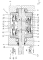
- FIG. 1 shows a longitudinal section through an axial piston pump 1.
- This has a pump housing 2, on which a not shown tank and a pressure port is formed.
- a drive shaft 4 is rotatably supported via a bearing assembly 6.
- a protruding from the pump housing 2 free end portion of the drive shaft 4 is connected to a drive motor, not shown.
- An inner bore 8 of the pump housing 2 accommodating the drive shaft 4 is expanded radially to form a pump chamber 10, in which two swash plates 12, 14 are mounted non-rotatably.
- the two swash plates 12, 14 each have an obliquely to the vertical in Fig. 1 extending support surface 16, on each of which a cylinder drum 18, 20 is supported.
- each cylinder drum 18, 20 has a plurality of cylinder sleeves 22, 23 in each of which a piston 24, 26 is immersed.
- the swash plates 12, 14 and correspondingly the cylinder drums 18, 20 arranged symmetrically to the vertically extending central axis M.
- the two pistons 24, 26 are each formed by the end portions of a double piston 28 which is rotatably inserted into a radially projecting drive flange 30 of the drive shaft 4.
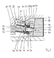
- the storage of the cylinder drums 18, 20 via spherical bearings 32, 34 which allow the occurring due to the inclination of the cylinder drums 18, 20 during the rotation of the shaft 4 tumbling motion. Further details of the arrangement will be explained with reference to the detailed illustration of the cylinder drum 20 in FIG. 2.
- the cylinder drum 20 has a driver 36, which is supported on the drive shaft 4 via the joint 34 and which is slidably supported with a radially widened flange part 40 on the obliquely set support surface 16 of the swashplate 14.
- the self-aligning bearing 34 engages in an inner bore of a hub-shaped projection 38 of the driver 36.
- the tension spring 48 is in turn supported on a support ring 58 which engages around the outer circumference of the cylinder sleeves 23 and the hub-shaped projection 38 and is supported in the axial direction by means of a support means 52.
- the cylinder sleeve 23 has a cylinder bore 54 into which the piston forming the end portion of the double piston 28 dips.
- the radial support of the cylinder sleeve 23 takes place by means of a ball stud 56 formed as a spherical cap 56, which dips into the cylinder bore 54 with a crowned head 58 and sealingly abuts on the inner peripheral wall of the cylinder bore 54 via a seal 60.
- the spherical cap 56 is inserted into a receptacle 62 of the flange part 40 described below in greater detail.
- the spherical cap 56 has a bore 64, which opens into an opening 66 of the flange 40, so that pressure medium from the cylinder sleeve 23 and the piston 26 limited cylinder space to the swash plate 14 and can flow in the reverse direction.
- this connecting channels not shown, formed via which in dependence on the rotational position (inner, outer dead center) of the cylinder drum 18, a connection to the tank or the pressure port is made to lead pressure medium to the cylinder chamber or pressurized high pressure fluid to a consumer to lead.
- the receptacle 62 has a bore portion 66 into which the part of the spherical cap 56 extending away from the head 58 is inserted.
- the bore portion 66 terminates in a kidney-shaped widened opening 68 which extends along a radial segment of the pitch circle along which the cylinder sleeves 23 are arranged.
- the axial length of the part of the spherical cap 56 inserted in the bore section 66 is selected such that an end section 70 protrudes into the opening 68.
- the fastening of the spherical cap 56 is then carried out by crimping these projecting into the kidney-shaped projection 68 end portions (see section X-Y in Fig. 1).
- kidney-shaped openings 68 space is created by these kidney-shaped openings 68 to allow a positive connection of the spherical cap 56 with the driver 36.
- the width b of the kidney-shaped opening 68 corresponds to the diameter of the bore section 66.
- the piston 26 is approximately conical, with its diameter starting from a waist 72 starting at a foot side, acting as a seal piston ring 74 flared and tapered after the piston ring 74 to an end face 76 again spherically is.
- the cone angle is chosen so that the peripheral surfaces of the piston 26 in the two dead centers (see Fig. 1 above: outer dead center, bottom 1: inner dead center) do not collide with the inner peripheral surfaces of the cylinder sleeves 22, 23 and just to this abutment, whereby in these end positions the seal must be ensured by the piston ring 74.
- the geometry of the arrangement according to the invention is chosen so that the cylinder sleeves 22, 23 are each aligned at the inner dead center vertically with respect to the end face 16 of the swash plate, so that the tilt angle at the inner dead center, d. H. during the pressure build-up minimal and thus a symmetrical support of the cylinder sleeves 22, 23 is ensured.
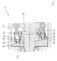
- Fig. 3 shows a partial view of another embodiment of an axial piston pump 1, in which only a cylinder drum 18 is shown.
- the further Zylindertrommmel 20 is executed in a corresponding manner.
- the embodiment shown in Fig. 3 differs from the above-described embodiments substantially in the storage of the cylinder sleeves 22.
- the structure of the double piston 28, the swash plates 12, 14 and the basic structure of the driver 36 is substantially identical, so that will be discussed below only on the different components.
- the cylinder sleeve 22 has a planar bottom surface 78, from which a pin 80 projects in the axial direction to the swash plate 12 out.
- the pin 80 has at its free end portion a head 58 with a seal 60, whose construction corresponds substantially to that of the above-described embodiment.
- the head 58 dips into a ball socket formed as a bearing receiver 82 and is biased by the tension spring 48 in this engaged position in which the spherical portions of the head 58 and the bearing seat 82 abut each other and thus form a universal joint.
- the end face 78 is arranged at a distance from the adjacent annular end face 42 of the driver 36, so that the sleeve to compensate for the transverse movement about the universal joint (82, 58) can tilt.
- a swash plate 12, 14 is shown with a constant angle of attack.
- this angle of attack for changing the stroke may also be variable.
- an axial piston machine with at least one swash plate and a cylinder drum supported thereon, which has a plurality of cylinder sleeves.
- the cylinder sleeves is associated with a row of pistons, which is connected to a shaft. According to the cylinder sleeves are hinged in the cylinder drum.
Landscapes
- Engineering & Computer Science (AREA)
- Mechanical Engineering (AREA)
- General Engineering & Computer Science (AREA)
- Reciprocating Pumps (AREA)
- Pistons, Piston Rings, And Cylinders (AREA)
Claims (17)
- Machine à pistons axiaux avec au moins un disque en nutation (12, 14), sur lequel s'appuie un tambour cylindrique (18, 20), dans lequel sont conduits des pistons (24, 26), qui sont en relation d'action avec un arbre (4), l'axe de rotation du tambour cylindrique (18, 20) étant placé par rapport à l'axe de rotation des pistons (24, 26) et le tambour cylindrique (18, 20) ayant une pluralité de douilles cylindriques (22, 23) en appui direct ou indirect sur le disque en nutation (12, 14),
caractérisée en ce que chaque douille cylindrique (22, 23) est montée de manière pivotante au moyen d'une articulation (58, 54 ; 58, 82). - Machine à pistons axiaux selon la revendication 1, l'articulation (58, 54 ; 58, 82) étant une articulation sphérique.
- Machine à pistons axiaux selon la revendication 1 ou 2, un tourillon d'articulation (56) traversant un fond de la douille cylindrique (22, 23) et constituant l'articulation avec une zone périphérique intérieure (54) de la douille cylindrique (22, 23).
- Machine à pistons axiaux selon la revendication 3, le tourillon d'articulation étant une calotte à bille (56), sur la tête convexe de laquelle (58) est prévu un joint (60) en appui contre la paroi périphérique intérieure (54) de la douille cylindrique (22, 23).
- Machine à pistons axiaux selon la revendication 1 ou 2, un tourillon d'articulation de l'articulation étant constitué par une cheville (80) portant un joint (60), dépassant axialement du fond des douilles cylindriques (22, 23).
- Machine à pistons axiaux selon l'une quelconque des revendications précédentes, les douilles cylindriques (22, 24) étant précontraintes dans une position d'appui.
- Machine à pistons axiaux selon la revendication 6, les douilles cylindriques (22, 23) présentant côté pied un bord d'appui (44) dépassant radialement, sur lequel est appliqué un ressort de tension (48).
- Machine à pistons axiaux selon la revendication 3 ou 4, chaque douille cylindrique (22, 24) ayant une surface de fond (46) conçue de manière convexe.
- Machine à pistons axiaux selon l'une quelconque des revendications précédentes, les douilles cylindriques (22, 23) étant conduites dans un entraîneur (36) du tambour cylindrique (18, 20), qui est en appui avec une surface frontale sur le disque de nutation (12, 14) et qui est relié à l'arbre (4) de manière fixe en rotation et permettant un mouvement de nutation.
- Machine à pistons axiaux selon la revendication 8, l'entraîneur (36) ayant un disque d'entraînement avec une partie de bride (40), sur la surface frontale circulaire (42) de laquelle s'appuient les douilles cylindriques (22, 23).
- Machine à pistons axiaux selon la revendication 10 et 3 ou 4, des percées (66, 86) étant disposées dans la partie de bride (40) en alignement à peu près axial par rapport à la douille cylindrique (22, 23), dans lesquelles percées est fixé respectivement un tourillon d'articulation (56).
- Machine à pistons axiaux selon la revendication 11, la percée (68) étant conçue en section en forme de rein et le tourillon d'articulation (56) étant fixé par concordance des formes par rabattage des zones limitrophes à ces sections en forme de rein (68).
- Machine à pistons axiaux selon la revendication 3 ou 5, le tourillon d'articulation (56) ou la cheville (80) étant traversés par un forage (64).
- Machine à pistons axiaux selon la revendication 5 ou l'une quelconque des revendications se rapportant à celle-ci, une tête convexe (58) de la cheville (80) étant placée dans un logement de palier (82) de la partie de bride (40).
- Machine à pistons axiaux selon l'une quelconque des revendications précédentes avec deux rangées de pistons (24, 26) orientées de manière opposée, auxquelles sont respectivement affectés un tambour cylindrique (18, 20) et un disque en nutation (12, 14).
- Machine à pistons axiaux selon l'une quelconque des revendications précédentes, les pistons étant conçus comme pistons doubles avec deux pistons orientés de manière opposée (24, 26), qui sont reliés à l'arbre (4) de manière fixe en rotation et dont les segments plongeant dans les douilles cylindriques (22, 23) s'agrandissent de manière conique d'un col (72) en direction des segments de piston (74).
- Machine à pistons axiaux selon l'une quelconque des revendications précédentes, celle-ci étant réalisée comme pompe à pistons axiaux.
Applications Claiming Priority (3)
| Application Number | Priority Date | Filing Date | Title |
|---|---|---|---|
| DE10259311 | 2002-12-18 | ||
| DE10259311 | 2002-12-18 | ||
| PCT/DE2003/004013 WO2004055369A1 (fr) | 2002-12-18 | 2003-12-05 | Machine a piston axiaux |
Publications (2)
| Publication Number | Publication Date |
|---|---|
| EP1573200A1 EP1573200A1 (fr) | 2005-09-14 |
| EP1573200B1 true EP1573200B1 (fr) | 2007-02-21 |
Family
ID=32519082
Family Applications (1)
| Application Number | Title | Priority Date | Filing Date |
|---|---|---|---|
| EP03782132A Expired - Lifetime EP1573200B1 (fr) | 2002-12-18 | 2003-12-05 | Machine a piston axiaux |
Country Status (5)
| Country | Link |
|---|---|
| US (1) | US7470116B2 (fr) |
| EP (1) | EP1573200B1 (fr) |
| AT (1) | ATE354729T1 (fr) |
| DE (2) | DE50306608D1 (fr) |
| WO (1) | WO2004055369A1 (fr) |
Cited By (2)
| Publication number | Priority date | Publication date | Assignee | Title |
|---|---|---|---|---|
| DE102010048553A1 (de) | 2010-10-14 | 2012-04-19 | Robert Bosch Gmbh | Triebwelle für eine Hydraulikmaschine und ein Verfahren zur Herstellung einer derartigen Triebwelle |
| DE102010052561A1 (de) | 2010-11-25 | 2012-05-31 | Robert Bosch Gmbh | Verfahren zur Anbindung von Kolben an eine Rotorplatte, Triebwelle und Hydraulikmaschine |
Families Citing this family (32)
| Publication number | Priority date | Publication date | Assignee | Title |
|---|---|---|---|---|
| US7874914B2 (en) | 1996-12-30 | 2011-01-25 | Igt | System and method for communicating game session information |
| EP1705372A1 (fr) * | 2005-03-11 | 2006-09-27 | Innas B.V. | Pompe variable ou moteur hydraulique |
| DE102005021029A1 (de) * | 2005-05-06 | 2006-11-09 | Linde Ag | Axialkolbenmaschine in Schrägscheibenbauweise mit Lagerung des Zylinderblocks auf einem Tragzapfen |
| DE102005058938A1 (de) * | 2005-11-11 | 2007-05-16 | Brueninghaus Hydromatik Gmbh | Hydrostatische Kolbenmaschine |
| DE102006003122A1 (de) * | 2005-11-25 | 2007-05-31 | Robert Bosch Gmbh | Axialkolbenmaschine |
| US20070251378A1 (en) * | 2006-04-27 | 2007-11-01 | Caterpillar Inc. | Dual flow axial piston pump |
| DE102006045442A1 (de) * | 2006-09-26 | 2008-03-27 | Robert Bosch Gmbh | Hydrostatische Antriebseinheit |
| DE102006045444A1 (de) * | 2006-09-26 | 2008-04-03 | Robert Bosch Gmbh | Axialkolbenmaschine |
| CN100485164C (zh) * | 2006-12-29 | 2009-05-06 | 郭有祥 | 陀螺轮转式引擎 |
| DE102007001795A1 (de) * | 2007-01-05 | 2008-07-10 | Robert Bosch Gmbh | Kolbenmaschine |
| DE102007011441A1 (de) | 2007-03-08 | 2008-09-11 | Robert Bosch Gmbh | Axialkolbenmaschine |
| US20090290997A1 (en) * | 2008-05-23 | 2009-11-26 | Caterpillar Inc. | Reduced flow pulsations in a tandem floating cup pump with an odd number of pistons |
| DE102010052067A1 (de) * | 2010-11-19 | 2012-05-24 | Robert Bosch Gmbh | Hydraulische Kolbenmaschine |
| AT511166B1 (de) * | 2011-03-02 | 2013-07-15 | Klaus Ing Voelkerer | Fluidenergiemaschine mit zwei gegenüberliegenden zylinderrotoren |
| DE102011113533A1 (de) * | 2011-09-15 | 2013-03-21 | Robert Bosch Gmbh | Hydrostatische Axialkolbenmaschine |
| DE102012222850A1 (de) | 2011-12-15 | 2013-06-20 | Robert Bosch Gmbh | Hydrostatische Axialkolbenmaschine |
| DE102012006292A1 (de) * | 2012-03-29 | 2013-10-02 | Robert Bosch Gmbh | Hydrostatische Axialkolbenmaschine |
| DE102012006289A1 (de) | 2012-03-29 | 2013-10-02 | Robert Bosch Gmbh | Hydrostatische Axialkolbenmaschine |
| DE102012006290A1 (de) | 2012-03-29 | 2013-10-02 | Robert Bosch Gmbh | Hydrotransformator |
| DE102013222602A1 (de) * | 2013-11-07 | 2015-05-07 | Robert Bosch Gmbh | Hydrostatische Axialkolbenmaschine |
| US20170335820A1 (en) * | 2014-11-08 | 2017-11-23 | Money S.R.L | Hydraulic machine with improved oscillating axial cylinders |
| ES2777213T3 (es) * | 2014-11-11 | 2020-08-04 | Danfoss As | Máquina de pistón axial |
| EP3246565B1 (fr) * | 2016-05-19 | 2019-09-18 | Innas B.V. | Dispositif hydraulique |
| EP3246567B1 (fr) | 2016-05-19 | 2022-03-09 | Innas B.V. | Dispositif hydraulique |
| EP3246566B1 (fr) | 2016-05-19 | 2018-12-19 | Innas B.V. | Dispositif hydraulique, procédé de fabrication d'un dispositif hydraulique et groupe de dispositifs hydrauliques |
| DE102016124048A1 (de) | 2016-12-12 | 2018-06-14 | Kamat Gmbh & Co. Kg | Axialkolbenpumpe mit großer Fördermenge bei geringer Drehzahl und Verwendung einer Kolbenpumpe in einer Windkraftanlage |
| EP3399186B1 (fr) * | 2017-05-03 | 2019-10-16 | Innas B.V. | Dispositif hydraulique |
| EP3477102B1 (fr) * | 2017-10-25 | 2020-12-16 | Innas B.V. | Dispositif hydraulique |
| US10968741B2 (en) | 2019-02-08 | 2021-04-06 | Volvo Car Corporation | Variable pre and de-compression control mechanism and method for hydraulic displacement pump |
| CN110630462A (zh) * | 2019-09-30 | 2019-12-31 | 北京工业大学 | 一种全水润滑的柔性浮杯式轴向柱塞泵 |
| EP4083424B1 (fr) | 2021-04-29 | 2023-11-15 | Innas B.V. | Dispositif hydraulique |
| CN116717453B (zh) * | 2023-08-09 | 2024-04-12 | 深圳市深旭机电工程设备有限公司 | 一种空调压缩机 |
Family Cites Families (25)
| Publication number | Priority date | Publication date | Assignee | Title |
|---|---|---|---|---|
| US3052098A (en) * | 1955-03-21 | 1962-09-04 | Ebert Heinrich | Hydrostatic axial piston fluid transmission |
| US2968286A (en) * | 1956-05-29 | 1961-01-17 | Reiners Walter | Hydraulic axial-piston machine |
| US3584543A (en) * | 1969-04-21 | 1971-06-15 | Gen Motors Corp | Elastic holddown member for the cylinder block of a fluid pump/motor |
| SE355640B (fr) * | 1970-04-03 | 1973-04-30 | New Invent Sa | |
| US3648567A (en) * | 1970-07-06 | 1972-03-14 | Gen Motors Corp | Variable displacement axial pump or motor |
| US4075933A (en) * | 1976-06-04 | 1978-02-28 | Gresen Manufacturing Company | Hydraulic pump or motor |
| CA1097545A (fr) * | 1977-02-02 | 1981-03-17 | Hermann Papst | Traduction non-disponible |
| DE2947553C2 (de) * | 1979-11-26 | 1982-03-25 | Hydromatik Gmbh, 7900 Ulm | Lagerung der Triebwelle einer Axialkolbenmaschine in Schrägachsenbauweise |
| US4361077A (en) * | 1980-06-16 | 1982-11-30 | Varitan, Inc. | Variable positive displacement fluid motor/pump apparatus |
| DE3333812C2 (de) * | 1983-09-19 | 1986-08-07 | Hydromatik GmbH, 7915 Elchingen | Schwenktrommel-Axialkolbenmaschine |
| US4945817A (en) * | 1989-10-24 | 1990-08-07 | General Motors Corporation | Axial piston device |
| US5112197A (en) * | 1990-10-01 | 1992-05-12 | General Motors Corporation | Cross groove joint socket plate torque restraint assembly for a variable displacement compressor |
| CA2145766A1 (fr) | 1992-09-14 | 1994-05-11 | Felice Pecorari | Machine volumetrique a pistons sans bielles |
| US5304043A (en) * | 1992-09-29 | 1994-04-19 | Avmed Compressor Corporation | Multiple axis rotary compressor |
| SK41195A3 (en) * | 1992-10-30 | 1995-10-11 | Felice Pecorari | Volumetric fluid machine |
| US5538401A (en) * | 1994-07-05 | 1996-07-23 | Denison Hydraulics Inc. | Axial piston pump |
| JPH10512644A (ja) * | 1995-01-19 | 1998-12-02 | エッセ・ア・イ ソチエタ アパレッキアツーレ イドラウリケ ソチエタ ペル アツィオニ | 湾曲したライナーを備えた容積装置 |
| JP3542411B2 (ja) * | 1995-06-27 | 2004-07-14 | キヤノン株式会社 | 画像形成装置 |
| WO2001098659A1 (fr) * | 2000-06-20 | 2001-12-27 | Folsom Technologies, Inc. | Pompe et moteur hydrauliques |
| US6354812B1 (en) * | 2000-06-29 | 2002-03-12 | Eaton Corporation | Adjustment maximum displacement stop for variable displacement piston pump |
| DE10055262A1 (de) * | 2000-11-08 | 2002-05-23 | Linde Ag | Hydrostatische Axialkolbenmaschine in Schrägscheibenbauweise |
| DE10124033B4 (de) * | 2001-05-16 | 2009-08-20 | Daimler Ag | Hubkolbenmaschine mit einer Schiebehülse |
| NL1020932C2 (nl) * | 2002-01-12 | 2003-07-15 | Innas Bv | Hydraulische inrichting. |
| US7014429B2 (en) * | 2003-03-06 | 2006-03-21 | The United States Of America As Represented By The Administrator Of The U.S. Environmental Protection Agency | High-efficiency, large angle, variable displacement hydraulic pump/motor |
| US7018181B2 (en) * | 2003-05-01 | 2006-03-28 | Wagner Spray Tech Corporation | Swashplate pump |
-
2003
- 2003-12-05 WO PCT/DE2003/004013 patent/WO2004055369A1/fr not_active Ceased
- 2003-12-05 DE DE50306608T patent/DE50306608D1/de not_active Expired - Lifetime
- 2003-12-05 AT AT03782132T patent/ATE354729T1/de not_active IP Right Cessation
- 2003-12-05 US US10/540,113 patent/US7470116B2/en not_active Expired - Fee Related
- 2003-12-05 DE DE10393875T patent/DE10393875D2/de not_active Expired - Fee Related
- 2003-12-05 EP EP03782132A patent/EP1573200B1/fr not_active Expired - Lifetime
Cited By (2)
| Publication number | Priority date | Publication date | Assignee | Title |
|---|---|---|---|---|
| DE102010048553A1 (de) | 2010-10-14 | 2012-04-19 | Robert Bosch Gmbh | Triebwelle für eine Hydraulikmaschine und ein Verfahren zur Herstellung einer derartigen Triebwelle |
| DE102010052561A1 (de) | 2010-11-25 | 2012-05-31 | Robert Bosch Gmbh | Verfahren zur Anbindung von Kolben an eine Rotorplatte, Triebwelle und Hydraulikmaschine |
Also Published As
| Publication number | Publication date |
|---|---|
| US7470116B2 (en) | 2008-12-30 |
| ATE354729T1 (de) | 2007-03-15 |
| US20060120881A1 (en) | 2006-06-08 |
| EP1573200A1 (fr) | 2005-09-14 |
| WO2004055369A1 (fr) | 2004-07-01 |
| DE50306608D1 (de) | 2007-04-05 |
| DE10393875D2 (de) | 2005-08-18 |
Similar Documents
| Publication | Publication Date | Title |
|---|---|---|
| EP1573200B1 (fr) | Machine a piston axiaux | |
| DE4105092C2 (fr) | ||
| EP0964997B1 (fr) | Moteur a pistons avec entrainement par disque de verrouillage | |
| DE2620910C2 (de) | Kolben für einen Brennkraftmotor | |
| EP1553291B1 (fr) | Machine a piston elevateur | |
| EP1394413B1 (fr) | Compresseur à piston de taille réduite | |
| EP1474617B1 (fr) | Machine a piston ou palier lisse de pivotement | |
| DE1703594B2 (de) | Axialkolbenpumpe | |
| DE102007011441A1 (de) | Axialkolbenmaschine | |
| DE102011113530A1 (de) | Lagerelement, Gleitlager und Hydromaschine mit einem derartigen Gleitlager | |
| DE69816932T2 (de) | Hermetischer motorverdichter für kältemaschinen | |
| DE4311432C2 (de) | Taumelscheibenkompressor mit variabler Förderleistung | |
| DE69820959T2 (de) | Gehäusedichtung für einen Taumelscheibenkompressor | |
| EP1607630A1 (fr) | Compresseur à piston | |
| EP1438505B1 (fr) | Element pompe et pompe a piston permettant la generation d'une haute pression de carburant | |
| EP0752530A1 (fr) | Machine à piston alternatif et entraînement par plateau oscillant | |
| DE102007051369B4 (de) | Hydrostatisches Schrägachsentriebwerk mit einem Synchronisierungsgelenk zur winkel-verstellbaren Triebverbindung eines Zylinderblocks mit einer Triebwelle | |
| DE10124033A1 (de) | Hubkolbenmaschine mit einer Schiebehülse | |
| DE10220610B4 (de) | Kolbenmaschine oder Drehgleitlagerung | |
| DE10315477B4 (de) | Axialkolbenverdichter, insbesondere CO2-Verdichter für Kraftfahrzeug-Klimaanlagen | |
| DE102007037199A1 (de) | Taumelringverdichter | |
| DE112004001050T5 (de) | Hybrid-Taumelelement-Pumpe | |
| EP1944510A1 (fr) | Machine à piston avec cylindre pivotable | |
| DE69723556T2 (de) | Taumelscheibenlagerung für einen kompressor mit variabler verdrängung | |
| DE19530978C2 (de) | Wellengelenk einer Exzenterschneckenpumpe |
Legal Events
| Date | Code | Title | Description |
|---|---|---|---|
| PUAI | Public reference made under article 153(3) epc to a published international application that has entered the european phase |
Free format text: ORIGINAL CODE: 0009012 |
|
| 17P | Request for examination filed |
Effective date: 20050613 |
|
| AK | Designated contracting states |
Kind code of ref document: A1 Designated state(s): AT BE BG CH CY CZ DE DK EE ES FI FR GB GR HU IE IT LI LU MC NL PT RO SE SI SK TR |
|
| GRAP | Despatch of communication of intention to grant a patent |
Free format text: ORIGINAL CODE: EPIDOSNIGR1 |
|
| GRAS | Grant fee paid |
Free format text: ORIGINAL CODE: EPIDOSNIGR3 |
|
| GRAA | (expected) grant |
Free format text: ORIGINAL CODE: 0009210 |
|
| AK | Designated contracting states |
Kind code of ref document: B1 Designated state(s): AT BE BG CH CY CZ DE DK EE ES FI FR GB GR HU IE IT LI LU MC NL PT RO SE SI SK TR |
|
| PG25 | Lapsed in a contracting state [announced via postgrant information from national office to epo] |
Ref country code: IE Free format text: LAPSE BECAUSE OF FAILURE TO SUBMIT A TRANSLATION OF THE DESCRIPTION OR TO PAY THE FEE WITHIN THE PRESCRIBED TIME-LIMIT Effective date: 20070221 Ref country code: NL Free format text: LAPSE BECAUSE OF FAILURE TO SUBMIT A TRANSLATION OF THE DESCRIPTION OR TO PAY THE FEE WITHIN THE PRESCRIBED TIME-LIMIT Effective date: 20070221 Ref country code: FI Free format text: LAPSE BECAUSE OF FAILURE TO SUBMIT A TRANSLATION OF THE DESCRIPTION OR TO PAY THE FEE WITHIN THE PRESCRIBED TIME-LIMIT Effective date: 20070221 Ref country code: SI Free format text: LAPSE BECAUSE OF FAILURE TO SUBMIT A TRANSLATION OF THE DESCRIPTION OR TO PAY THE FEE WITHIN THE PRESCRIBED TIME-LIMIT Effective date: 20070221 Ref country code: DK Free format text: LAPSE BECAUSE OF FAILURE TO SUBMIT A TRANSLATION OF THE DESCRIPTION OR TO PAY THE FEE WITHIN THE PRESCRIBED TIME-LIMIT Effective date: 20070221 |
|
| REG | Reference to a national code |
Ref country code: GB Ref legal event code: FG4D Free format text: NOT ENGLISH |
|
| REG | Reference to a national code |
Ref country code: CH Ref legal event code: EP |
|
| REF | Corresponds to: |
Ref document number: 50306608 Country of ref document: DE Date of ref document: 20070405 Kind code of ref document: P |
|
| REG | Reference to a national code |
Ref country code: IE Ref legal event code: FG4D Free format text: LANGUAGE OF EP DOCUMENT: GERMAN |
|
| PG25 | Lapsed in a contracting state [announced via postgrant information from national office to epo] |
Ref country code: SE Free format text: LAPSE BECAUSE OF FAILURE TO SUBMIT A TRANSLATION OF THE DESCRIPTION OR TO PAY THE FEE WITHIN THE PRESCRIBED TIME-LIMIT Effective date: 20070521 |
|
| PG25 | Lapsed in a contracting state [announced via postgrant information from national office to epo] |
Ref country code: BG Free format text: LAPSE BECAUSE OF EXPIRATION OF PROTECTION Effective date: 20070522 |
|
| GBT | Gb: translation of ep patent filed (gb section 77(6)(a)/1977) |
Effective date: 20070501 |
|
| PG25 | Lapsed in a contracting state [announced via postgrant information from national office to epo] |
Ref country code: ES Free format text: LAPSE BECAUSE OF FAILURE TO SUBMIT A TRANSLATION OF THE DESCRIPTION OR TO PAY THE FEE WITHIN THE PRESCRIBED TIME-LIMIT Effective date: 20070601 |
|
| PG25 | Lapsed in a contracting state [announced via postgrant information from national office to epo] |
Ref country code: PT Free format text: LAPSE BECAUSE OF FAILURE TO SUBMIT A TRANSLATION OF THE DESCRIPTION OR TO PAY THE FEE WITHIN THE PRESCRIBED TIME-LIMIT Effective date: 20070723 |
|
| NLV1 | Nl: lapsed or annulled due to failure to fulfill the requirements of art. 29p and 29m of the patents act | ||
| REG | Reference to a national code |
Ref country code: IE Ref legal event code: FD4D |
|
| EN | Fr: translation not filed | ||
| PG25 | Lapsed in a contracting state [announced via postgrant information from national office to epo] |
Ref country code: SK Free format text: LAPSE BECAUSE OF FAILURE TO SUBMIT A TRANSLATION OF THE DESCRIPTION OR TO PAY THE FEE WITHIN THE PRESCRIBED TIME-LIMIT Effective date: 20070221 |
|
| PLBE | No opposition filed within time limit |
Free format text: ORIGINAL CODE: 0009261 |
|
| STAA | Information on the status of an ep patent application or granted ep patent |
Free format text: STATUS: NO OPPOSITION FILED WITHIN TIME LIMIT |
|
| PG25 | Lapsed in a contracting state [announced via postgrant information from national office to epo] |
Ref country code: CZ Free format text: LAPSE BECAUSE OF FAILURE TO SUBMIT A TRANSLATION OF THE DESCRIPTION OR TO PAY THE FEE WITHIN THE PRESCRIBED TIME-LIMIT Effective date: 20070221 Ref country code: RO Free format text: LAPSE BECAUSE OF FAILURE TO SUBMIT A TRANSLATION OF THE DESCRIPTION OR TO PAY THE FEE WITHIN THE PRESCRIBED TIME-LIMIT Effective date: 20070221 |
|
| 26N | No opposition filed |
Effective date: 20071122 |
|
| PG25 | Lapsed in a contracting state [announced via postgrant information from national office to epo] |
Ref country code: FR Free format text: LAPSE BECAUSE OF FAILURE TO SUBMIT A TRANSLATION OF THE DESCRIPTION OR TO PAY THE FEE WITHIN THE PRESCRIBED TIME-LIMIT Effective date: 20071012 Ref country code: GR Free format text: LAPSE BECAUSE OF FAILURE TO SUBMIT A TRANSLATION OF THE DESCRIPTION OR TO PAY THE FEE WITHIN THE PRESCRIBED TIME-LIMIT Effective date: 20070522 |
|
| BERE | Be: lapsed |
Owner name: BOSCH REXROTH A.G. Effective date: 20071231 |
|
| PG25 | Lapsed in a contracting state [announced via postgrant information from national office to epo] |
Ref country code: MC Free format text: LAPSE BECAUSE OF NON-PAYMENT OF DUE FEES Effective date: 20071231 |
|
| REG | Reference to a national code |
Ref country code: CH Ref legal event code: PL |
|
| PG25 | Lapsed in a contracting state [announced via postgrant information from national office to epo] |
Ref country code: BE Free format text: LAPSE BECAUSE OF NON-PAYMENT OF DUE FEES Effective date: 20071231 |
|
| PG25 | Lapsed in a contracting state [announced via postgrant information from national office to epo] |
Ref country code: LI Free format text: LAPSE BECAUSE OF NON-PAYMENT OF DUE FEES Effective date: 20071231 Ref country code: CH Free format text: LAPSE BECAUSE OF NON-PAYMENT OF DUE FEES Effective date: 20071231 Ref country code: DE Free format text: LAPSE BECAUSE OF NON-PAYMENT OF DUE FEES Effective date: 20080701 |
|
| PG25 | Lapsed in a contracting state [announced via postgrant information from national office to epo] |
Ref country code: FR Free format text: LAPSE BECAUSE OF FAILURE TO SUBMIT A TRANSLATION OF THE DESCRIPTION OR TO PAY THE FEE WITHIN THE PRESCRIBED TIME-LIMIT Effective date: 20070221 |
|
| PG25 | Lapsed in a contracting state [announced via postgrant information from national office to epo] |
Ref country code: EE Free format text: LAPSE BECAUSE OF FAILURE TO SUBMIT A TRANSLATION OF THE DESCRIPTION OR TO PAY THE FEE WITHIN THE PRESCRIBED TIME-LIMIT Effective date: 20070221 |
|
| PG25 | Lapsed in a contracting state [announced via postgrant information from national office to epo] |
Ref country code: AT Free format text: LAPSE BECAUSE OF NON-PAYMENT OF DUE FEES Effective date: 20071205 |
|
| PG25 | Lapsed in a contracting state [announced via postgrant information from national office to epo] |
Ref country code: CY Free format text: LAPSE BECAUSE OF FAILURE TO SUBMIT A TRANSLATION OF THE DESCRIPTION OR TO PAY THE FEE WITHIN THE PRESCRIBED TIME-LIMIT Effective date: 20070221 |
|
| PG25 | Lapsed in a contracting state [announced via postgrant information from national office to epo] |
Ref country code: LU Free format text: LAPSE BECAUSE OF NON-PAYMENT OF DUE FEES Effective date: 20071205 |
|
| PG25 | Lapsed in a contracting state [announced via postgrant information from national office to epo] |
Ref country code: HU Free format text: LAPSE BECAUSE OF FAILURE TO SUBMIT A TRANSLATION OF THE DESCRIPTION OR TO PAY THE FEE WITHIN THE PRESCRIBED TIME-LIMIT Effective date: 20070822 Ref country code: TR Free format text: LAPSE BECAUSE OF FAILURE TO SUBMIT A TRANSLATION OF THE DESCRIPTION OR TO PAY THE FEE WITHIN THE PRESCRIBED TIME-LIMIT Effective date: 20070221 |
|
| REG | Reference to a national code |
Ref country code: DE Ref legal event code: R073 Ref document number: 50306608 Country of ref document: DE |
|
| REG | Reference to a national code |
Ref country code: DE Ref legal event code: R119 Ref document number: 50306608 Country of ref document: DE Ref country code: DE Ref legal event code: R409 Ref document number: 50306608 Country of ref document: DE |
|
| REG | Reference to a national code |
Ref country code: DE Ref legal event code: R073 Ref document number: 50306608 Country of ref document: DE |
|
| REG | Reference to a national code |
Ref country code: DE Ref legal event code: R074 Ref document number: 50306608 Country of ref document: DE Ref country code: DE Ref legal event code: R409 Ref document number: 50306608 Country of ref document: DE |
|
| REG | Reference to a national code |
Ref country code: DE Ref legal event code: R409 Ref document number: 50306608 Country of ref document: DE Ref country code: DE Ref legal event code: R074 Ref document number: 50306608 Country of ref document: DE Effective date: 20111027 |
|
| PGRI | Patent reinstated in contracting state [announced from national office to epo] |
Ref country code: DE Effective date: 20111215 |
|
| PGFP | Annual fee paid to national office [announced via postgrant information from national office to epo] |
Ref country code: GB Payment date: 20121218 Year of fee payment: 10 Ref country code: IT Payment date: 20121219 Year of fee payment: 10 |
|
| PGFP | Annual fee paid to national office [announced via postgrant information from national office to epo] |
Ref country code: DE Payment date: 20130225 Year of fee payment: 10 |
|
| REG | Reference to a national code |
Ref country code: DE Ref legal event code: R119 Ref document number: 50306608 Country of ref document: DE |
|
| GBPC | Gb: european patent ceased through non-payment of renewal fee |
Effective date: 20131205 |
|
| REG | Reference to a national code |
Ref country code: DE Ref legal event code: R074 Ref document number: 50306608 Country of ref document: DE |
|
| REG | Reference to a national code |
Ref country code: DE Ref legal event code: R119 Ref document number: 50306608 Country of ref document: DE Effective date: 20110701 Ref country code: DE Ref legal event code: R119 Ref document number: 50306608 Country of ref document: DE Effective date: 20140701 |
|
| PG25 | Lapsed in a contracting state [announced via postgrant information from national office to epo] |
Ref country code: DE Free format text: LAPSE BECAUSE OF NON-PAYMENT OF DUE FEES Effective date: 20140701 |
|
| PG25 | Lapsed in a contracting state [announced via postgrant information from national office to epo] |
Ref country code: GB Free format text: LAPSE BECAUSE OF NON-PAYMENT OF DUE FEES Effective date: 20131205 |
|
| PG25 | Lapsed in a contracting state [announced via postgrant information from national office to epo] |
Ref country code: IT Free format text: LAPSE BECAUSE OF NON-PAYMENT OF DUE FEES Effective date: 20131231 |
|
| PG25 | Lapsed in a contracting state [announced via postgrant information from national office to epo] |
Ref country code: IT Free format text: LAPSE BECAUSE OF NON-PAYMENT OF DUE FEES Effective date: 20131205 |