EP1573245B1 - Elements photoemetteurs transparents et procede de fabrication - Google Patents
Elements photoemetteurs transparents et procede de fabrication Download PDFInfo
- Publication number
- EP1573245B1 EP1573245B1 EP03808117A EP03808117A EP1573245B1 EP 1573245 B1 EP1573245 B1 EP 1573245B1 EP 03808117 A EP03808117 A EP 03808117A EP 03808117 A EP03808117 A EP 03808117A EP 1573245 B1 EP1573245 B1 EP 1573245B1
- Authority
- EP
- European Patent Office
- Prior art keywords
- notches
- light emitting
- light
- cutting tool
- members
- Prior art date
- Legal status (The legal status is an assumption and is not a legal conclusion. Google has not performed a legal analysis and makes no representation as to the accuracy of the status listed.)
- Expired - Lifetime
Links
- 238000000034 method Methods 0.000 title claims description 5
- 238000004519 manufacturing process Methods 0.000 title claims description 3
- 238000005520 cutting process Methods 0.000 claims abstract description 16
- 238000009826 distribution Methods 0.000 claims description 26
- 239000003086 colorant Substances 0.000 claims description 2
- 230000005540 biological transmission Effects 0.000 claims 1
- 238000007788 roughening Methods 0.000 claims 1
- 239000011248 coating agent Substances 0.000 description 7
- 238000000576 coating method Methods 0.000 description 7
- 239000000463 material Substances 0.000 description 7
- 239000003973 paint Substances 0.000 description 5
- 238000009434 installation Methods 0.000 description 3
- 230000003287 optical effect Effects 0.000 description 3
- PPBRXRYQALVLMV-UHFFFAOYSA-N Styrene Chemical compound C=CC1=CC=CC=C1 PPBRXRYQALVLMV-UHFFFAOYSA-N 0.000 description 2
- 230000008901 benefit Effects 0.000 description 2
- 230000003247 decreasing effect Effects 0.000 description 2
- 238000004382 potting Methods 0.000 description 2
- 230000001681 protective effect Effects 0.000 description 2
- JOYRKODLDBILNP-UHFFFAOYSA-N Ethyl urethane Chemical compound CCOC(N)=O JOYRKODLDBILNP-UHFFFAOYSA-N 0.000 description 1
- BQCADISMDOOEFD-UHFFFAOYSA-N Silver Chemical compound [Ag] BQCADISMDOOEFD-UHFFFAOYSA-N 0.000 description 1
- NIXOWILDQLNWCW-UHFFFAOYSA-N acrylic acid group Chemical group C(C=C)(=O)O NIXOWILDQLNWCW-UHFFFAOYSA-N 0.000 description 1
- 239000000853 adhesive Substances 0.000 description 1
- 230000001070 adhesive effect Effects 0.000 description 1
- 230000004075 alteration Effects 0.000 description 1
- 238000005266 casting Methods 0.000 description 1
- 230000008859 change Effects 0.000 description 1
- 230000008878 coupling Effects 0.000 description 1
- 238000010168 coupling process Methods 0.000 description 1
- 238000005859 coupling reaction Methods 0.000 description 1
- 230000001419 dependent effect Effects 0.000 description 1
- 239000000835 fiber Substances 0.000 description 1
- 239000011521 glass Substances 0.000 description 1
- 229910052736 halogen Inorganic materials 0.000 description 1
- 150000002367 halogens Chemical class 0.000 description 1
- 230000004048 modification Effects 0.000 description 1
- 238000012986 modification Methods 0.000 description 1
- 238000000465 moulding Methods 0.000 description 1
- 229910052754 neon Inorganic materials 0.000 description 1
- GKAOGPIIYCISHV-UHFFFAOYSA-N neon atom Chemical compound [Ne] GKAOGPIIYCISHV-UHFFFAOYSA-N 0.000 description 1
- 239000004033 plastic Substances 0.000 description 1
- 238000004023 plastic welding Methods 0.000 description 1
- 239000004417 polycarbonate Substances 0.000 description 1
- 229920000515 polycarbonate Polymers 0.000 description 1
- 229910052709 silver Inorganic materials 0.000 description 1
- 239000004332 silver Substances 0.000 description 1
Images


Classifications
-
- G—PHYSICS
- G02—OPTICS
- G02B—OPTICAL ELEMENTS, SYSTEMS OR APPARATUS
- G02B6/00—Light guides; Structural details of arrangements comprising light guides and other optical elements, e.g. couplings
- G02B6/0001—Light guides; Structural details of arrangements comprising light guides and other optical elements, e.g. couplings specially adapted for lighting devices or systems
- G02B6/0011—Light guides; Structural details of arrangements comprising light guides and other optical elements, e.g. couplings specially adapted for lighting devices or systems the light guides being planar or of plate-like form
- G02B6/0033—Means for improving the coupling-out of light from the light guide
- G02B6/0035—Means for improving the coupling-out of light from the light guide provided on the surface of the light guide or in the bulk of it
- G02B6/0036—2-D arrangement of prisms, protrusions, indentations or roughened surfaces
-
- G—PHYSICS
- G02—OPTICS
- G02B—OPTICAL ELEMENTS, SYSTEMS OR APPARATUS
- G02B6/00—Light guides; Structural details of arrangements comprising light guides and other optical elements, e.g. couplings
- G02B6/0001—Light guides; Structural details of arrangements comprising light guides and other optical elements, e.g. couplings specially adapted for lighting devices or systems
- G02B6/0005—Light guides; Structural details of arrangements comprising light guides and other optical elements, e.g. couplings specially adapted for lighting devices or systems the light guides being of the fibre type
- G02B6/001—Light guides; Structural details of arrangements comprising light guides and other optical elements, e.g. couplings specially adapted for lighting devices or systems the light guides being of the fibre type the light being emitted along at least a portion of the lateral surface of the fibre
-
- G—PHYSICS
- G02—OPTICS
- G02B—OPTICAL ELEMENTS, SYSTEMS OR APPARATUS
- G02B6/00—Light guides; Structural details of arrangements comprising light guides and other optical elements, e.g. couplings
- G02B6/0001—Light guides; Structural details of arrangements comprising light guides and other optical elements, e.g. couplings specially adapted for lighting devices or systems
- G02B6/0011—Light guides; Structural details of arrangements comprising light guides and other optical elements, e.g. couplings specially adapted for lighting devices or systems the light guides being planar or of plate-like form
- G02B6/0013—Means for improving the coupling-in of light from the light source into the light guide
- G02B6/0015—Means for improving the coupling-in of light from the light source into the light guide provided on the surface of the light guide or in the bulk of it
- G02B6/002—Means for improving the coupling-in of light from the light source into the light guide provided on the surface of the light guide or in the bulk of it by shaping at least a portion of the light guide, e.g. with collimating, focussing or diverging surfaces
- G02B6/0021—Means for improving the coupling-in of light from the light source into the light guide provided on the surface of the light guide or in the bulk of it by shaping at least a portion of the light guide, e.g. with collimating, focussing or diverging surfaces for housing at least a part of the light source, e.g. by forming holes or recesses
-
- Y—GENERAL TAGGING OF NEW TECHNOLOGICAL DEVELOPMENTS; GENERAL TAGGING OF CROSS-SECTIONAL TECHNOLOGIES SPANNING OVER SEVERAL SECTIONS OF THE IPC; TECHNICAL SUBJECTS COVERED BY FORMER USPC CROSS-REFERENCE ART COLLECTIONS [XRACs] AND DIGESTS
- Y10—TECHNICAL SUBJECTS COVERED BY FORMER USPC
- Y10T—TECHNICAL SUBJECTS COVERED BY FORMER US CLASSIFICATION
- Y10T29/00—Metal working
- Y10T29/40—Umbrella-frame making
Definitions
- This invention relates to transparent light emitting members that have specially shaped notches or grooves in one or more surfaces to create a selected light output distribution from such members and their method of manufacture.
- light transparent members including for example rods, panels, films, sheets and plates
- such notches are typically relatively sharp grooves, which do not scatter light very finely.
- the sharp grooves make the light emitting members more susceptible to breakage during installation or when placed under tension.
- the light emitting members may be used, for example, as a back light and/or front light for transparent or translucent devices such as LCDs, dials, gauges, pictures, point of sale advertising, decorative devices, and so on.
- such light emitting members may have special usages in optical scanning and array devices and the like.
- the light emitting members have shallow notches or grooves in a surface thereof that are generally U or C shaped.
- the light emitting members have shallow notches or grooves in one or more surfaces that scatter the light emitted from the members.
- the shallow notches or grooves reduce the risk of breakage of the light emitting members during installation or when the members are placed under tension.
- the light emitting members are relatively inexpensive and easy to mold.
- the light emitting members allow for easy low volume manufacturability of the members with any desired amount of smoothness or roughness on the faces of the notches or grooves.
- the light emitting members may have special arcuate shapes for use in special lighting applications.
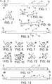
- Fig. 1 there is shown one transparent light emitting member 1 according to an example not forming part of the present invention in the shape of an elongated rod 2 having a pattern of notches or grooves 3 in a surface 4 of the member for causing light that is transmitted through the member by internal reflection to be reflected or refracted out of the member as well known in the art.
- the notches or grooves 3 of the present invention rather than being relatively sharp grooves as is conventional practice, are rounded shallow notches or grooves each having a generally U or C cross-sectional shape as schematically shown in Fig. 2 .
- These rounded notches or grooves 3 may have a minimum depth and width of radius of no more than a few thousandths of an inch, depending on the length and thickness of the light emitting member, and have the advantage that they will scatter the light more finely than sharp grooves and will reduce the risk of breakage of the members during installation or when the members are placed under tension. Also the surfaces of the notches may be smooth or textured or roughened as desired to extract less or more light out through the notches or grooves.
- Such light emitting members may be molded or cast or machined or cut out of any suitable transparent, clear or colored (including scintillating or fluorescent) material including glass or plastic such as acrylic, polycarbonate, styrene, or urethane or the like.
- the notches or grooves 3 may be painted or covered with a reflective color. Also, different notches may be coated with different colors for decorative or visibility purposes when the light emitting member is lighted by one or more white light sources.
- Such light emitting members may be lighted from one or both end edges using any suitable light source 5.
- the rod-like light emitting member 2 of Fig. 1 is shown lighted from one end by a narrow angle light emitting diode (LED) 6 inserted in a slot, cavity or opening 7 machined, molded, cast or otherwise formed in the light emitting member.
- Light source 5 may be held in place within the opening 7, for example, by an interference fit or by embedding, potting or bonding the light source in place using a suitable embedding, potting or bonding material 8. Bonding can also be accomplished using a variety of methods that do not incorporate extra material, for example, thermobonding, heat staking, ultrasonic or plastic welding or the like. Other methods of bonding include insert molding and casting around the light source.
- the light source 5 may also be held adjacent an edge of light emitting member 1 using for example a few drops of adhesive, or by heat shrinking a heat-shrinkable tube 10 around both the light source 5 and an edge of the light emitting member 1 as schematically shown in Fig. 4a .
- a remote light source 5 may be optically coupled to the edge of the light emitting member by focusing the light source on the input surface 11 of a light guide 12 suitably connected to the light emitting member as schematically shown in Fig. 4b .
- suitable holes 7 may be molded or cast in one or more edges of the light emitting member for receipt of the LEDs as schematically shown in Fig. 1 .
- LEDs as the light source has the benefit that LEDs produce very little heat, consume small amounts of electric power, have a relatively long life, are relatively inexpensive, are not damaged by vibration, and do not produce EMI.
- other types of light sources may also be used including, for example, an arc lamp, an incandescent bulb, a lens end bulb, a line light, a halogen lamp, a neon bulb, a fluorescent tube, a fiber optic light pipe transmitting from a remote source, a laser or laser diode, or any other suitable light source.
- the density and/or depth or size of the notches 3 may be varied along the surface of the light emitting member 1 in order to obtain a selected light output distribution from the member. For example, the amount of light traveling through the light emitting member will ordinarily be greater in areas closer to the light source than in areas further removed from the light source.
- the pattern of notches or grooves 3 may be used to adjust for the light variances within the light emitting member, for example, by placing the notches 3 closer together as the distance from the light source increases to provide a more uniform light output distribution from the light emitting member. Also, depending on the length and cross-sectional thickness of the light emitting member, the notches 3 may be made progressively deeper and/or wider with increased distance from the light source to provide a more uniform light output from the member.
- the light emitting member When the light emitting member is lighted from one end only as shown in Fig. 1 , placing the notches 3 progressively closer together and/or making the notches progressively deeper and/or wider as the distance from the lighted end edge increases will result in a more uniform light output distribution from the light emitting member. Further, the faces of the notches may be made progressively more textured or rougher with increased distance from the light source to provide a more uniform light output distribution from the member.
- a reflective film or coating 15 may be provided on the non-lighted end edge of the light emitting member (if lighted from only one end edge as schematically shown in Fig. 1 ) as by applying a reflective film to such non-lighted end edge or coating such non-lighted end edge with white or silver reflective paint to minimize light loss from such non-lighted end edge.
- the light emitting member 1 may also be lighted from both ends as schematically shown in Fig. 3 for increased light output.
- the notches or grooves 3 may be placed closer and closer together as the distance from both lighted end edges increases toward the middle where the concentration of the notches will be greatest to provide a more uniform light output distribution from the light emitting member.
- Fig. 5 shows the rod-like light emitting member 1 according to an example not forming part of the invention as having a cylindrical cross-sectional shape 16.
- light emitting member 1 may have other cross-sectional shapes as well for varying the output ray angle distribution of the emitted light to suit a particular application. For example, changing the cross-sectional shape of the member 1 from the cylindrical cross section 16 shown in Fig. 5 to an elliptical cross section 17 as shown in Fig. 6 will narrow the view angle of the light produced, whereas changing the cross-sectional shape to a semi-cylindrical cross section 18 as shown in Fig. 7 will widen the view angle.
- a rectangular cross-sectional shape 19 as shown in Fig. 8 or a triangular cross-sectional shape 20 as shown in Fig. 9 may be used.
- the light output distribution from a light emitting member 1 with a rectangular cross-sectional shape 19 can be made brighter by notching three of the four sides 4, 21, 22 and 23 instead of just one of the sides 4 as schematically shown in Fig. 10 .
- Figs. 11 and 12 show a variation of the notching pattern along a rod-like light emitting member 1 according to the present invention in which the notches 3 closest to the lighted end 25 are made relatively parallel to the light emitting member to cause a relatively small percentage of the transmitted light to be emitted and the notches 3 further removed from the lighted end are made more and more perpendicular to the axis of the light emitting member as the distance from the lighted end increases to cause a greater percentage of the transmitted light to be emitted to produce a more uniform light output distribution from the light emitting member.
- Figs. 13 and 14 show another pattern of notches 3 extending along the length of a rod-like light emitting member 1 that is lighted from both ends.
- the notches 3 are located along an arc 26, with the notches closest to the top surface of the member adjacent the middle producing brighter light when viewed from the proper angle.
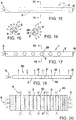
- Figs. 15 and 16 show another rod-like light emitting member 1 according to an example not forming part of the invention in which a rounded shallow notch or groove 3 extends along the length of the member for causing light to be emitted therefrom.
- the groove 3 may be coated with a suitable reflective material 15 such as reflective paint or tape as schematically shown in Fig. 16 to increase its effectiveness in reflecting light.
- the depth of the light emitting groove 3 may if desired progressively increase as the distance from the lighted end increases to produce a more uniform light output distribution.
- the unlighted end edge of the light emitting member 1 may be coated with a suitable reflective material 15 such as reflective paint or tape.
- the groove 3 may if desired be made shallower at the ends and progressively deeper from the ends toward the middle to produce a more uniform light output distribution from the member.
- the rod-like light emitting member 1 shown in Figs. 15 and 16 has a generally cylindrical cross section
- the light emitting member may have other cross-sectional shapes including for example the semi-cylindrical, elliptical, square and triangular shapes previously discussed to obtain a desired light output distribution to suit a particular application.
- the notches or grooves may be provided on more than one side of the members as desired.
- any of the light emitting members of the present invention may be curved along their length to suit a particular application.
- Figs. 17 and 18 show another rod-like light emitting member 1 according to an example not forming part of the invention in which a plurality of longitudinally spaced notches 3 in the shape of rounded shallow dimples 28 are provided along the length of the member for causing light to be emitted therefrom. If the light emitting member is lighted from one end only as shown in Fig. 17 , the dimples 28 may be made progressively deeper and/or closer together as the distance from the light source increases to produce a more uniform light output distribution.
- the surface of the dimples 28 may be coated with a suitable reflective material 15 such as reflective paint or tape as schematically shown in Fig. 18 . Also, the unlighted end edge of the light emitting member may similarly be coated with a suitable reflective coating 15.
- the dimples 28 may be made progressively deeper or closer together as the distance from both ends increases toward the middle with the depth of the dimples being greatest or the spacing between dimples being closest together at the middle to produce a more uniform light output distribution. While the light emitting member 1 shown in Figs. 17 and 18 has a cylindrical cross-sectional shape, the member may have any of the other cross-sectional shapes previously described to fit a particular application. Also, the dimples 28 may be elongated and be provided along more than one side of the member if desired. In addition, the member itself may be curved along its length to suit a particular application.
- Figs. 19 and 20 show another light emitting member 30 according to an example not forming part of the invention in the shape of a panel 31 having a greater cross-sectional width than thickness and bottom and top surfaces 32 and 33.
- the panel 31 may be lighted from one or both end edges and also from one or both side edges as schematically shown in Fig. 20 .
- the number of light sources 5 utilized will depend on the size of the panel as well as the type of light sources used and the brightness and uniformity of light output desired. If LEDs 6 are used as the light source, wide viewing angle LEDs may be used for lighting the panel as opposed to the narrow viewing angle LEDs used to light rod-like light emitting members.
- a pattern of rounded shallow generally U or C shaped notches or grooves 3 having the cross-sectional shape shown in Fig. 2 may be provided in one or more surfaces of the panel member 31 for causing transmitted light to be emitted therefrom. If the panel is lighted from only one end edge, the notches or grooves 3 may be placed closer together as the distance from the lighted end edge increases to provide a more uniform light output distribution from the panel. Moreover, additional notches or grooves 3' may be provided in one or more edges of the panel member 31 in order to reflect the light wherever it is needed.
- the light emitting panel 31 shown in Figs. 19 and 20 is substantially rectangular in shape.
- the light emitting panel 31 may also be arcuately shaped as schematically shown in Figs. 21-28 .
- the curved side edges 34 and 35 of the arcuately shaped panels 31 should either be highly polished or covered with a reflective material or coating 15 such as paint to reflect light back into the panel.
- Such arcuately shaped panels may be lighted from one end edge as schematically shown in Fig. 21 or lighted from both end edges as schematically shown in Fig. 23 .
- the arcuate panels may have sideways enlargements 36 along their length as schematically shown in Fig. 23 .
- the ends of the arcuately shaped panels may be joined together at 40 and lighted by a single light source 5 as schematically shown in Fig. 25 .
- the notches 3 may be placed closer and closer together (or made deeper and deeper or larger and larger) as the distance from the lighted edges increases as schematically shown in Figs. 19-26 .
- the notches 3 may be grouped in special patterns on selected areas of the panel 31 as schematically shown in Figs. 27 and 28 .
- the arcuate shaped panels 31 are shown in Figs. 21-28 as being generally ring shaped. However, such panels may also have other arcuate shapes including for example "J", "S” or "U” shapes.
- any of the light emitting members of the invention may also have patterns of rounded shallow notches or grooves on more than one side.
- Fig. 29 shows a light emitting member 1 or 30 having a pattern of notches or grooves 3 on both the top and bottom surfaces of the member to produce a specified lighting pattern.
- any of the light emitting members of the invention may have a suitable reflective coating or film on different surfaces of the members to reflect light back into or through the members.
- Fig. 30 schematically shows one such light emitting member 1 or 30 having a reflective layer 15 on the notched side 4 or 32 to reflect light back through the other side and on the end edge opposite the lighted end edge to reflect light back into the member.
- any of the light emitting members 1 or 30 of the invention may have a suitable sheet, film or coating 41 such as a diffuser, brightness enhancement film or other optical device adjacent one or more sides of the member as schematically shown in Fig. 31 to alter the light output distribution from the member, for example, make it more even or brighter or change the view angle.
- a suitable sheet, film or coating 41 such as a diffuser, brightness enhancement film or other optical device adjacent one or more sides of the member as schematically shown in Fig. 31 to alter the light output distribution from the member, for example, make it more even or brighter or change the view angle.
- a transparent UV protective film or sleeve 42 may cover the light emitting members 1 or 30 as schematically shown in Fig. 32 . Also a white or mirror-type background may be provided for the members if desired.
- These various light emitting members with rounded shallow notches or grooves are relatively easy and inexpensive to mold. Also such members allow for easy low volume manufacturability because little or no tooling is required for custom applications.
- Low volume manufacturability may involve using a low speed circular cutting tool such as a ball mill, with a high feed rate of the cutting tool and/or members such that the cutting tool will leave tool marks on the face of the notches or grooves thus producing a textured or roughened surface to extract more of the light through the notches or grooves.
- the amount of texturing or roughness of the notches or grooves may be varied along the surface of the light emitting members in order to obtain a selected light output distribution from the members by varying the cutter speed and/or feed rate.
- the notches or grooves may be made progressively more textured or roughened with increased distance from the light source to provide a more uniform light output distribution from the members.
- the depth of the notches or grooves may be progressively increased or decreased by progressively increasing or decreasing the depth of the cutting tool.
Landscapes
- Physics & Mathematics (AREA)
- General Physics & Mathematics (AREA)
- Optics & Photonics (AREA)
- Planar Illumination Modules (AREA)
- Surface Treatment Of Glass (AREA)
- Glass Compositions (AREA)
- Shaping Of Tube Ends By Bending Or Straightening (AREA)
Claims (5)
- Illuminateur (1) comprenant un élément d'émission de lumière (2) transparent de type tige comportant au moins un bord d'extrémité de réception de lumière (25) pour recevoir de la lumière d'une source de lumière (5) pour une transmission à travers ledit élément (2) par réflexion interne, et un motif d'encoches (3) peu profondes sensiblement en forme de U ou de C dans une surface dudit élément (2) pour amener la lumière à être réfléchie ou réfractée hors dudit élément, les axes d'au moins certaines desdites encoches (3) dans ladite surface étant orientés selon différents angles par rapport à l'axe dudit élément (2) le long de la longueur dudit élément (2) pour obtenir une distribution de sortie de lumière sélectionnée à partir dudit élément (2), caractérisé en ce que lesdites encoches (3) sont inclinées plus près d'une direction perpendiculaire à l'axe dudit élément (2) alors que la distance desdites encoches (3) par rapport au dit bord d'extrémité de réception de lumière (25) augmente pour obtenir une distribution de sortie de lumière plus uniforme à partir dudit élément (2).
- Illuminateur selon la revendication 1, dans lequel différentes encoches parmi lesdites encoches (3) sont revêtues de couleurs différentes à des fins décoratives lorsque ledit élément (2) est éclairé par une source de lumière blanche.
- Illuminateur selon la revendication 1, dans lequel ladite source de lumière (5) est fixée au dit bord (25) par une gaine tubulaire (10) dont les extrémités opposées sont thermorétractées sur ladite source de lumière (5) et ledit bord (25).
- Procédé de fabrication de l'illuminateur (1) selon la revendication 1, consistant à usiner le motif d'encoches (3) peu profondes dans au moins une surface de l'élément d'émission de lumière (2) transparent de type tige en utilisant un outil de coupe circulaire, et commander la vitesse relative de l'outil de coupe et l'avance de l'outil de coupe par rapport à l'élément (2) pour produire une surface rugosifiée sur les encoches (3),
caractérisé en ce que :au moins l'une de la vitesse relative de l'outil de coupe et de l'avance de l'outil de coupe par rapport à l'élément (2) est modifiée pendant l'usinage d'au moins certaines des encoches (3) pour modifier le degré de rugosité de la surface sur les encoches (3). - Procédé selon la revendication 4, dans lequel la profondeur de l'outil de coupe est modifiée pendant l'usinage d'au moins certaines des encoches (3) pour modifier la profondeur de ces encoches (3).
Applications Claiming Priority (3)
| Application Number | Priority Date | Filing Date | Title |
|---|---|---|---|
| US264576 | 2002-10-04 | ||
| US10/264,576 US6910783B2 (en) | 2002-10-04 | 2002-10-04 | Transparent light emitting members and method of manufacture |
| PCT/US2003/031206 WO2004033959A2 (fr) | 2002-10-04 | 2003-10-02 | Elements photoemetteurs transparents et procede de fabrication |
Publications (3)
| Publication Number | Publication Date |
|---|---|
| EP1573245A2 EP1573245A2 (fr) | 2005-09-14 |
| EP1573245A4 EP1573245A4 (fr) | 2007-08-01 |
| EP1573245B1 true EP1573245B1 (fr) | 2012-04-11 |
Family
ID=32042265
Family Applications (1)
| Application Number | Title | Priority Date | Filing Date |
|---|---|---|---|
| EP03808117A Expired - Lifetime EP1573245B1 (fr) | 2002-10-04 | 2003-10-02 | Elements photoemetteurs transparents et procede de fabrication |
Country Status (5)
| Country | Link |
|---|---|
| US (2) | US6910783B2 (fr) |
| EP (1) | EP1573245B1 (fr) |
| AT (1) | ATE553404T1 (fr) |
| AU (1) | AU2003277225A1 (fr) |
| WO (1) | WO2004033959A2 (fr) |
Families Citing this family (158)
| Publication number | Priority date | Publication date | Assignee | Title |
|---|---|---|---|---|
| US6783269B2 (en) * | 2000-12-27 | 2004-08-31 | Koninklijke Philips Electronics N.V. | Side-emitting rod for use with an LED-based light engine |
| US6910783B2 (en) * | 2002-10-04 | 2005-06-28 | Lumitex, Inc. | Transparent light emitting members and method of manufacture |
| US20070248307A1 (en) * | 2002-10-04 | 2007-10-25 | Page David J | Transparent light emitting members and method of manufacture |
| US20040156195A1 (en) * | 2002-10-16 | 2004-08-12 | Robertson Jonas J. | Illuminated acrylic flashlight and tool chest light utility light |
| US20060113544A1 (en) * | 2002-12-13 | 2006-06-01 | Koji Otsuka | Semiconductor light-emitting device, method for manufacturing same, and linear light source |
| US7249878B2 (en) * | 2003-01-10 | 2007-07-31 | Eastman Kodak Company | Multi-layer illuminated package |
| US20040228143A1 (en) * | 2003-05-16 | 2004-11-18 | Squicciarini John B. | Transparent rod with optical fiber core |
| DE10332393A1 (de) * | 2003-07-17 | 2005-02-03 | Schefenacker Vision Systems Germany Gmbh & Co. Kg | Leuchte für Fahrzeuge, vorzugsweise Kraftfahrzeuge |
| US20050013141A1 (en) * | 2003-07-17 | 2005-01-20 | Espinoza-Ibarra Ricardo Ernesto | Method and system for independently displaying a plurality of visual signals |
| US7275845B2 (en) * | 2003-10-14 | 2007-10-02 | Miller John F | Illuminatable windshield assembly |
| US20050094415A1 (en) * | 2003-10-29 | 2005-05-05 | Bor-Dong Cheng | Body molding for car |
| US20050237763A1 (en) * | 2004-04-22 | 2005-10-27 | Swanson William P | Light dispersing device |
| GB0422796D0 (en) * | 2004-10-14 | 2004-11-17 | Graham Morton | An illumination device |
| TWM272416U (en) * | 2004-11-23 | 2005-08-11 | Baycom Opto Electronics Technology Co Ltd | Decorative light transmission device |
| US7374324B2 (en) * | 2005-02-09 | 2008-05-20 | Dura Global Technologies, Inc. | LED molded light guide |
| US7537353B2 (en) * | 2005-06-20 | 2009-05-26 | Continental Automotive Systems Us, Inc. | Flood and back lit instrument cluster |
| JP4585390B2 (ja) * | 2005-06-23 | 2010-11-24 | アルプス電気株式会社 | 環状導光体 |
| DE102005035232A1 (de) * | 2005-07-25 | 2007-02-01 | Erich Utsch Ag | Halter für ein Kfz-Kennzeichenschild |
| US20070076428A1 (en) * | 2005-09-30 | 2007-04-05 | Chia-Yeh Wu | Festoon lamp |
| US7401948B2 (en) * | 2005-10-17 | 2008-07-22 | Visteon Global Technologies, Inc. | Near field lens having reduced size |
| US7160010B1 (en) | 2005-11-15 | 2007-01-09 | Visteon Global Technologies, Inc. | Light manifold for automotive light module |
| US7489453B2 (en) * | 2005-11-15 | 2009-02-10 | Visteon Global Technologies, Inc. | Side emitting near field lens |
| US7564070B2 (en) * | 2005-11-23 | 2009-07-21 | Visteon Global Technologies, Inc. | Light emitting diode device having a shield and/or filter |
| US7438454B2 (en) * | 2005-11-29 | 2008-10-21 | Visteon Global Technologies, Inc. | Light assembly for automotive lighting applications |
| FR2895780B1 (fr) * | 2005-12-29 | 2014-08-22 | Saint Gobain | Structure lumineuse a guide plan et a source quasi ponctuelle et ses applications |
| US8109666B2 (en) * | 2006-01-10 | 2012-02-07 | Rohm Co., Ltd. | Light guiding member and linear light source apparatus using same |
| US8409088B2 (en) | 2006-01-18 | 2013-04-02 | Invuity, Inc. | Retractor illumination system |
| US7593615B2 (en) * | 2006-02-10 | 2009-09-22 | Rpc Photonics, Inc. | Optical devices for guiding illumination |
| JP2007259396A (ja) * | 2006-02-23 | 2007-10-04 | Rohm Co Ltd | 線状光源装置、並びに、これを用いた画像読取装置および平面ディスプレイ装置 |
| US7588342B2 (en) * | 2006-04-24 | 2009-09-15 | Energy Focus, Inc. | Lighted refrigerated display case with remote light source |
| KR20070108794A (ko) * | 2006-05-08 | 2007-11-13 | 미래나노텍(주) | 광학 시트 및 상기 광학 시트가 구비된 액정표시장치의백라이트 어셈블리 |
| US9364755B1 (en) | 2006-05-08 | 2016-06-14 | Nintendo Co., Ltd. | Methods and apparatus for using illumination marks for spatial pointing |
| US7549782B2 (en) * | 2006-05-11 | 2009-06-23 | Avago Technologies Ecbu Ip (Singapore) Pte. Ltd. | Semiconductor light source configured as a light tube |
| US7228052B1 (en) * | 2006-05-12 | 2007-06-05 | Lumina Technology Co., Ltd. | LED light pipe structure |
| US8047987B2 (en) * | 2006-05-26 | 2011-11-01 | Invuity, Inc. | Blade insert illuminator |
| GB2438440B (en) * | 2006-05-26 | 2008-04-23 | Design Led Products Ltd | A composite light guiding device |
| US7618176B2 (en) * | 2006-06-22 | 2009-11-17 | Avago Technologies General Ip (Singapore) Pte. Ltd. | Solid state light source adapted for remote illumination |
| US20080310187A1 (en) * | 2006-06-28 | 2008-12-18 | Yujing Technology Co., Ltd. | Light guide device for vehicle lamps |
| US20080002400A1 (en) * | 2006-06-28 | 2008-01-03 | Yujing Technology Co., Ltd. | Illuminating ring |
| US7302156B1 (en) * | 2006-07-12 | 2007-11-27 | Lumio Inc. | Optical system |
| JP4463246B2 (ja) * | 2006-07-26 | 2010-05-19 | 株式会社フジクラ | 線状照明装置用の導光体 |
| DE102006037797B4 (de) * | 2006-08-04 | 2016-06-30 | Automotive Lighting Reutlingen Gmbh | Kraftfahrzeugleuchte |
| EP1890077A1 (fr) | 2006-08-15 | 2008-02-20 | Hella KG Hueck & Co. | Guide d'ondes pour appareil d'éclairage de véhicule |
| DE112007001950T5 (de) * | 2006-08-21 | 2009-07-02 | Innotec Corporation, Zeeland | Elektrische Vorrichtung mit platinenloser Montageanordnung für elektrische Komponenten |
| DE102006045157B4 (de) * | 2006-09-25 | 2020-06-18 | Robert Bosch Gmbh | Handwerkzeugmaschine |
| US20080188277A1 (en) | 2007-02-01 | 2008-08-07 | Ritter Janice E | Electronic Game Device And Method Of Using The Same |
| US7712933B2 (en) * | 2007-03-19 | 2010-05-11 | Interlum, Llc | Light for vehicles |
| US8408773B2 (en) | 2007-03-19 | 2013-04-02 | Innotec Corporation | Light for vehicles |
| US7554742B2 (en) * | 2007-04-17 | 2009-06-30 | Visteon Global Technologies, Inc. | Lens assembly |
| US7478941B2 (en) * | 2007-05-30 | 2009-01-20 | Pixon Technologies Corp. | FLICKERLESS light source |
| US7556411B2 (en) * | 2007-07-06 | 2009-07-07 | Pixon Technologies Corp. | Flickerless light source |
| JP2009021158A (ja) * | 2007-07-13 | 2009-01-29 | Rohm Co Ltd | 線状光源装置 |
| TWM328573U (en) * | 2007-09-28 | 2008-03-11 | Inventec Appliances Corp | Multi-axis light-guiding tube module |
| US8088066B2 (en) | 2007-10-24 | 2012-01-03 | Invuity, Inc. | Blade insert illuminator |
| CN101451682B (zh) * | 2007-12-06 | 2011-06-08 | 富士迈半导体精密工业(上海)有限公司 | 环形照明装置 |
| EP2232592B1 (fr) | 2007-12-12 | 2013-07-17 | Innotec Corporation | Procédé de surmouler une carte de circuit |
| EP2073406B1 (fr) * | 2007-12-17 | 2014-02-12 | Siemens Aktiengesellschaft | Machine dotée d'une communication optique entre une première partie de machine et une seconde partie de machine pivotant en fonction de la première partie de machine |
| US7815339B2 (en) | 2008-01-09 | 2010-10-19 | Innotec Corporation | Light module |
| JP2009218076A (ja) * | 2008-03-10 | 2009-09-24 | Koito Mfg Co Ltd | 車両用灯具 |
| US7972053B2 (en) * | 2008-04-08 | 2011-07-05 | Nurturenergy, Inc. | Lighting apparatus |
| WO2009128517A1 (fr) * | 2008-04-17 | 2009-10-22 | 株式会社フジクラ | Organe d’orientation de lumière et dispositif d’affichage utilisant un tel corps |
| WO2009128516A1 (fr) * | 2008-04-17 | 2009-10-22 | 株式会社フジクラ | Dispositif d’affichage |
| CN101598299B (zh) * | 2008-06-05 | 2012-01-25 | 鸿富锦精密工业(深圳)有限公司 | 光源模组及使用该光源模组的游戏装置 |
| US8066416B2 (en) * | 2008-06-09 | 2011-11-29 | Federal-Mogul Ignition Company | Head lamp assembly and accent lighting therefor |
| CN101603666A (zh) * | 2008-06-11 | 2009-12-16 | 鸿富锦精密工业(深圳)有限公司 | 灯具 |
| US8016441B2 (en) * | 2008-06-24 | 2011-09-13 | Continental Automotive Systems Us, Inc. | One LED illuminated cluster |
| WO2010003273A1 (fr) * | 2008-07-08 | 2010-01-14 | 海立尔股份有限公司 | Module de rétroéclairage flexible |
| KR101479339B1 (ko) * | 2008-07-09 | 2015-01-05 | 삼성전자주식회사 | 광가이드를 이용한 조명 장치 및 이를 구비한 휴대 단말기 |
| US11382711B2 (en) | 2008-08-13 | 2022-07-12 | Invuity, Inc. | Cyclo olefin polymer and copolymer medical devices |
| BE1017952A3 (nl) * | 2008-11-21 | 2010-01-12 | Brelec B V B A | Lichtgeleider met zijdelingse lichtextractie. |
| US8070341B2 (en) * | 2008-12-18 | 2011-12-06 | Visteon Global Technologies, Inc. | Light pipe with uniformly lit appearance |
| FR2942326B1 (fr) * | 2009-02-18 | 2011-07-01 | Faurecia Interieur Ind | Ensemble de guidage de lumiere |
| KR101044987B1 (ko) * | 2009-02-19 | 2011-06-29 | (주)휴먼라이테크 | 발광다이오드를 이용한 조명장치 |
| US20100315811A1 (en) * | 2009-06-10 | 2010-12-16 | Shih-Chou Chen | Curved light guiding illuminator |
| TWM373518U (en) * | 2009-06-25 | 2010-02-01 | Wistron Corp | Light guide plate and membrane keyboard having the light guide plate |
| GB2472078A (en) * | 2009-07-23 | 2011-01-26 | Visteon Global Tech Inc | A light-pipe for illuminating a display area |
| US20110058351A1 (en) * | 2009-09-07 | 2011-03-10 | Wen-Chang Yang | Control panel structure of fitness equipment |
| EP2302294A1 (fr) * | 2009-09-18 | 2011-03-30 | 3M Innovative Properties Company | Connecteur |
| US9096170B2 (en) * | 2009-09-28 | 2015-08-04 | Rite-Hite Holding Corporation | Light fixtures for doorways and other areas |
| TWI454639B (zh) * | 2009-12-28 | 2014-10-01 | Hon Hai Prec Ind Co Ltd | 環形導光結構及採用該環形導光結構之背光模組 |
| KR101028308B1 (ko) * | 2010-01-15 | 2011-04-12 | 엘지이노텍 주식회사 | 백라이트 유닛 및 표시 장치 |
| US20110219648A1 (en) * | 2010-03-12 | 2011-09-15 | Trevor James | Led edge-lit signage utilizing digital print technology |
| US8201983B2 (en) * | 2010-06-01 | 2012-06-19 | Young Lighting Technology Inc. | Illuminating device |
| US9766385B2 (en) * | 2010-06-17 | 2017-09-19 | Philips Lighting Holding B.V. | Illumination device with waveguide and LEDs |
| US8545305B2 (en) | 2010-06-28 | 2013-10-01 | Wms Gaming Inc. | Devices, systems, and methods for dynamically simulating a component of a wagering game |
| US8956006B2 (en) | 2010-08-23 | 2015-02-17 | Energy Focus, Inc. | Elongated LED lamp for replacing a fluorescent lamp |
| CA2809631A1 (fr) | 2010-09-09 | 2012-03-15 | Energy Focus, Inc. | Systeme d'eclairage allonge |
| US8702292B2 (en) | 2010-09-22 | 2014-04-22 | Terralux, Inc. | Linear illumination devices having light guides and LED-based illumination modules |
| US20120087149A1 (en) * | 2010-10-08 | 2012-04-12 | Visteon Global Technologies, Inc. | Ultra-thin light guide for cluster gauge illumination over display structures |
| DE202010014013U1 (de) * | 2010-10-08 | 2010-12-16 | Wolters Cat & Dog Gmbh | Leuchthalsband |
| US20120092874A1 (en) * | 2010-10-15 | 2012-04-19 | Chao-Liang Lin | Light-guiding pillar |
| US9657907B2 (en) * | 2010-12-14 | 2017-05-23 | Bridgelux Inc. | Side light LED troffer tube |
| EP2649923A4 (fr) * | 2011-04-07 | 2014-05-28 | Olympus Medical Systems Corp | Endoscope et dispositif d'éclairement pour endoscope |
| DE102011085385B4 (de) | 2011-10-28 | 2026-01-08 | Bayerische Motoren Werke Aktiengesellschaft | Beleuchtungseinrichtung für ein Kraftfahrzeug |
| US9303204B2 (en) * | 2011-11-30 | 2016-04-05 | Chin Piao Kuo | Planar light source device and method of manufacturing same |
| US9171418B2 (en) | 2011-12-15 | 2015-10-27 | Bally Gaming, Inc. | Gaming devices and gaming systems with multiple display device arrangement |
| KR20140137363A (ko) | 2012-02-17 | 2014-12-02 | 쓰리엠 이노베이티브 프로퍼티즈 컴파니 | 왜상 도광체 |
| US9036964B2 (en) | 2012-02-17 | 2015-05-19 | 3M Innovative Properties Company | Optical light guide coupler |
| US9823404B2 (en) | 2012-02-17 | 2017-11-21 | 3M Innovative Properties Company | Backlight system |
| DE112013002944T5 (de) | 2012-06-13 | 2015-02-19 | Innotec, Corp. | Flexibler Hohllichtleiter |
| US8870428B2 (en) * | 2012-06-20 | 2014-10-28 | Energy Focus, Inc. | Elongated LED lighting arrangement |
| US20130343046A1 (en) * | 2012-06-22 | 2013-12-26 | Chang Ching TSAI | LED Light Tube |
| EP2815691A4 (fr) * | 2012-11-07 | 2015-11-25 | Olympus Corp | Endoscope |
| US9366396B2 (en) | 2013-01-30 | 2016-06-14 | Cree, Inc. | Optical waveguide and lamp including same |
| WO2014117330A1 (fr) * | 2013-01-30 | 2014-08-07 | Nokia Corporation | Couvercle, dispositif électronique portable l'utilisant et son procédé de fabrication |
| US9411086B2 (en) | 2013-01-30 | 2016-08-09 | Cree, Inc. | Optical waveguide assembly and light engine including same |
| US9442243B2 (en) | 2013-01-30 | 2016-09-13 | Cree, Inc. | Waveguide bodies including redirection features and methods of producing same |
| US9625638B2 (en) | 2013-03-15 | 2017-04-18 | Cree, Inc. | Optical waveguide body |
| US10234616B2 (en) | 2013-01-30 | 2019-03-19 | Cree, Inc. | Simplified low profile module with light guide for pendant, surface mount, wall mount and stand alone luminaires |
| US9869432B2 (en) | 2013-01-30 | 2018-01-16 | Cree, Inc. | Luminaires using waveguide bodies and optical elements |
| US9690029B2 (en) | 2013-01-30 | 2017-06-27 | Cree, Inc. | Optical waveguides and luminaires incorporating same |
| US9291320B2 (en) | 2013-01-30 | 2016-03-22 | Cree, Inc. | Consolidated troffer |
| US10436969B2 (en) | 2013-01-30 | 2019-10-08 | Ideal Industries Lighting Llc | Optical waveguide and luminaire incorporating same |
| US10502899B2 (en) * | 2013-03-15 | 2019-12-10 | Ideal Industries Lighting Llc | Outdoor and/or enclosed structure LED luminaire |
| US9798072B2 (en) | 2013-03-15 | 2017-10-24 | Cree, Inc. | Optical element and method of forming an optical element |
| US9920901B2 (en) | 2013-03-15 | 2018-03-20 | Cree, Inc. | LED lensing arrangement |
| US10209429B2 (en) | 2013-03-15 | 2019-02-19 | Cree, Inc. | Luminaire with selectable luminous intensity pattern |
| US10379278B2 (en) * | 2013-03-15 | 2019-08-13 | Ideal Industries Lighting Llc | Outdoor and/or enclosed structure LED luminaire outdoor and/or enclosed structure LED luminaire having outward illumination |
| US10436970B2 (en) | 2013-03-15 | 2019-10-08 | Ideal Industries Lighting Llc | Shaped optical waveguide bodies |
| US10400984B2 (en) | 2013-03-15 | 2019-09-03 | Cree, Inc. | LED light fixture and unitary optic member therefor |
| US9366799B2 (en) | 2013-03-15 | 2016-06-14 | Cree, Inc. | Optical waveguide bodies and luminaires utilizing same |
| US10166402B2 (en) | 2013-05-16 | 2019-01-01 | Excelitas Technologies Corp. | Visible light photo-disinfection patch |
| US10107951B2 (en) * | 2013-05-24 | 2018-10-23 | 3M Innovative Properties Company | Lightguides having angled light extracting surfaces and specific optical absorption coefficient |
| CN105659027B (zh) | 2013-07-18 | 2018-03-13 | 夸克星有限责任公司 | 源光注入不平行于装置光轴的照明装置 |
| US20150049505A1 (en) * | 2013-08-14 | 2015-02-19 | Garmin Switzerland Gmbh | Transparent light guide |
| CN104456425B (zh) * | 2013-09-13 | 2017-09-19 | 扬升照明股份有限公司 | 面光源 |
| TWI563203B (en) * | 2013-09-18 | 2016-12-21 | Nifco Inc | Illumination device |
| JP5907143B2 (ja) * | 2013-10-23 | 2016-04-20 | 豊田合成株式会社 | 照明装置 |
| WO2015126573A1 (fr) | 2014-02-24 | 2015-08-27 | Quarkstar Llc | Module de luminaire ayant un guide de lumière avec une face d'extrémité de réorientation |
| US20150252958A1 (en) * | 2014-03-07 | 2015-09-10 | Lunera Lighting, Inc. | Edge-Lit LED Retrofit for a Fluorescent Tube |
| US9658382B2 (en) * | 2014-03-28 | 2017-05-23 | Quarkstar Llc | Luminaire module having a light guide with redirecting interfaces |
| TWI565983B (zh) * | 2014-05-29 | 2017-01-11 | 元太科技工業股份有限公司 | 光學模組、包含其之顯示裝置及其製造方法 |
| US9521885B2 (en) * | 2014-05-30 | 2016-12-20 | Apple Inc. | Woven display |
| US12372219B2 (en) * | 2014-05-30 | 2025-07-29 | Cree Lighting Usa Llc | LED luminaire with a cavity, finned interior, and a curved outer wall extending from a surface on which the light source is mounted |
| US20160016510A1 (en) * | 2014-07-17 | 2016-01-21 | Continental Automotive Systems, Inc. | Light guide film applied at instrument cluster |
| US9965918B2 (en) | 2014-07-31 | 2018-05-08 | Bally Gaming, Inc. | Overlapping LCD displays for a gaming machine |
| US10330845B2 (en) | 2014-09-24 | 2019-06-25 | Rebo Lighting & Electronics, Llc | Waveguide for controlled light distribution |
| RU2696671C2 (ru) * | 2015-01-06 | 2019-08-05 | Филипс Лайтинг Холдинг Б.В. | Светоизлучающее устройство для светящихся поверхностей |
| CN105864721B (zh) * | 2015-01-24 | 2019-05-21 | 鸿富锦精密工业(武汉)有限公司 | 面板导光装置 |
| EP3295079B1 (fr) * | 2015-05-14 | 2025-07-09 | LMPG Inc. | Ensembles panneaux électroluminescents comprenant une source de lumière montée sur le fond et guides de lumière associés |
| DE102015011904B4 (de) * | 2015-09-11 | 2026-03-26 | MENTOR GmbH & Co Präzisions-Bauteile KG | Beleuchtungsvorrichtung mit einer ebenen Lichtleiterplatte |
| FR3041741B1 (fr) | 2015-09-30 | 2017-11-24 | Valeo Iluminacion Sa | Dispositif optique et systeme de signalisation et/ou d'eclairage pour un vehicule automobile |
| US10060590B2 (en) * | 2015-10-05 | 2018-08-28 | Fu An Industrial Co., Ltd. | Light ring structure for vehicle lamp |
| FR3045133B1 (fr) * | 2015-12-15 | 2020-08-07 | Morpho | Dispositif d'eclairage et procede de fabrication d'un patch d'un tel dispositif |
| US10416377B2 (en) | 2016-05-06 | 2019-09-17 | Cree, Inc. | Luminaire with controllable light emission |
| US11719882B2 (en) | 2016-05-06 | 2023-08-08 | Ideal Industries Lighting Llc | Waveguide-based light sources with dynamic beam shaping |
| US10175653B1 (en) * | 2016-09-21 | 2019-01-08 | Apple Inc. | Watch glow light band |
| JP6890287B2 (ja) * | 2017-09-25 | 2021-06-18 | パナソニックIpマネジメント株式会社 | 照明器具 |
| US10739513B2 (en) | 2018-08-31 | 2020-08-11 | RAB Lighting Inc. | Apparatuses and methods for efficiently directing light toward and away from a mounting surface |
| US10801679B2 (en) | 2018-10-08 | 2020-10-13 | RAB Lighting Inc. | Apparatuses and methods for assembling luminaires |
| US10723262B1 (en) * | 2019-06-11 | 2020-07-28 | Continental Automotive Systems, Inc. | Light guide for ring gauge illumination |
| WO2021173431A1 (fr) | 2020-02-24 | 2021-09-02 | Milwaukee Electric Tool Corporation | Outil à percussion |
| WO2021209492A1 (fr) * | 2020-04-15 | 2021-10-21 | CommScope Connectivity Belgium BV | Dispositif et procédé de scellement de câbles dans des enceintes de télécommunications |
| CN212653400U (zh) | 2020-06-12 | 2021-03-05 | 米沃奇电动工具公司 | 具有照明组件的摆动电动工具 |
| CN212553690U (zh) | 2020-06-12 | 2021-02-19 | 米沃奇电动工具公司 | 摆动电动工具 |
| AT525331B1 (de) * | 2021-07-16 | 2023-09-15 | Rech Alexander | Mobile Elektronikvorrichtung |
| JP2024047269A (ja) * | 2022-09-26 | 2024-04-05 | 株式会社マキタ | 電動作業機及びねじ締め工具 |
| US12201280B2 (en) | 2023-04-27 | 2025-01-21 | Alcon Inc. | Console light guide device |
Citations (3)
| Publication number | Priority date | Publication date | Assignee | Title |
|---|---|---|---|---|
| EP0594089A1 (fr) * | 1992-10-19 | 1994-04-27 | Minnesota Mining And Manufacturing Company | Dispositifs d'illumination et fibres optiques utilisables dans ceux-ci |
| EP1139015A1 (fr) * | 2000-03-31 | 2001-10-04 | Mitsubishi Denki Kabushiki Kaisha | Feu avant, dispositif d'affichage à cristaux liquides et assistant numérique personnel |
| US20020131275A1 (en) * | 2001-01-16 | 2002-09-19 | Estec Co., Ltd. | LED illuminating device and lighting apparatus employing the same |
Family Cites Families (26)
| Publication number | Priority date | Publication date | Assignee | Title |
|---|---|---|---|---|
| US2354367A (en) * | 1940-02-26 | 1944-07-25 | Ford David Otis | Display sign |
| US3829675A (en) | 1973-04-30 | 1974-08-13 | R Mariani | Lighting means for underwater illumination |
| US3892959A (en) | 1973-11-02 | 1975-07-01 | Gte Automatic Electric Lab Inc | Edge-lighted panel arrangement |
| US4630895A (en) | 1985-06-06 | 1986-12-23 | Motorola, Inc. | LCD lightguide |
| US5005108A (en) | 1989-02-10 | 1991-04-02 | Lumitex, Inc. | Thin panel illuminator |
| SE463384B (sv) * | 1989-03-29 | 1990-11-12 | Ericsson Traffic Systems Ab | Trafikljuslins samt foerfarande foer framstaellning av saadan |
| JP2601766Y2 (ja) | 1992-08-31 | 1999-12-06 | 日本電産コパル株式会社 | 面発光装置 |
| US5386347A (en) * | 1992-10-02 | 1995-01-31 | Photo Craft Co., Ltd. | Illuminating apparatus and a method of manufacturing an edge light conductor for use therein |
| JP2630714B2 (ja) | 1992-10-08 | 1997-07-16 | 茶谷産業株式会社 | 面照明装置 |
| DE69418502T2 (de) | 1993-02-01 | 2000-02-24 | Tosoh Corp | Vorrichtung zur Hintergrund-Beleuchtung |
| US5598280A (en) | 1993-03-23 | 1997-01-28 | Dai Nippon Printing Co., Ltd. | Film lens and a surface light source using the same |
| EP0678904A1 (fr) * | 1994-04-12 | 1995-10-25 | Lsi Logic Corporation | Procédé pour découper un wafer à l'aide de coupes multiples |
| US5575549A (en) | 1994-08-12 | 1996-11-19 | Enplas Corporation | Surface light source device |
| US5521342A (en) | 1994-12-27 | 1996-05-28 | General Motors Corporation | Switch having combined light pipe and printed circuit board |
| JP3187280B2 (ja) * | 1995-05-23 | 2001-07-11 | シャープ株式会社 | 面照明装置 |
| US5613751A (en) | 1995-06-27 | 1997-03-25 | Lumitex, Inc. | Light emitting panel assemblies |
| US6712481B2 (en) | 1995-06-27 | 2004-03-30 | Solid State Opto Limited | Light emitting panel assemblies |
| US5895115A (en) | 1996-01-16 | 1999-04-20 | Lumitex, Inc. | Light emitting panel assemblies for use in automotive applications and the like |
| US5961198A (en) | 1996-02-02 | 1999-10-05 | Hitachi, Ltd. | Liquid crystal display device and method of manufacturing backlighting light guide panel therefor |
| US6014919A (en) * | 1996-09-16 | 2000-01-18 | Precision Vascular Systems, Inc. | Method and apparatus for forming cuts in catheters, guidewires, and the like |
| US5845038A (en) * | 1997-01-28 | 1998-12-01 | Minnesota Mining And Manufacturing Company | Optical fiber illumination system |
| JPH10221273A (ja) * | 1997-02-10 | 1998-08-21 | Konica Corp | 導光部材、光検出装置、欠陥検査装置 |
| US5995288A (en) | 1997-04-22 | 1999-11-30 | Dai Nippon Printing Co., Ltd. | Optical sheet optical sheet lamination light source device, and light-transmissive type display apparatus |
| US6565225B2 (en) * | 2000-07-19 | 2003-05-20 | Sanyo Electric Co., Ltd. | Bar-shaped light guide, beam lighting device using the bar-shaped light guide, and surface lighting device using the beam lighting device |
| CA2388251C (fr) * | 2001-05-31 | 2007-09-11 | John Starkey | Broyeur a boulets |
| US6910783B2 (en) * | 2002-10-04 | 2005-06-28 | Lumitex, Inc. | Transparent light emitting members and method of manufacture |
-
2002
- 2002-10-04 US US10/264,576 patent/US6910783B2/en not_active Expired - Lifetime
-
2003
- 2003-10-02 WO PCT/US2003/031206 patent/WO2004033959A2/fr not_active Ceased
- 2003-10-02 AU AU2003277225A patent/AU2003277225A1/en not_active Abandoned
- 2003-10-02 EP EP03808117A patent/EP1573245B1/fr not_active Expired - Lifetime
- 2003-10-02 AT AT03808117T patent/ATE553404T1/de active
-
2005
- 2005-05-11 US US11/126,655 patent/US20050210643A1/en not_active Abandoned
Patent Citations (3)
| Publication number | Priority date | Publication date | Assignee | Title |
|---|---|---|---|---|
| EP0594089A1 (fr) * | 1992-10-19 | 1994-04-27 | Minnesota Mining And Manufacturing Company | Dispositifs d'illumination et fibres optiques utilisables dans ceux-ci |
| EP1139015A1 (fr) * | 2000-03-31 | 2001-10-04 | Mitsubishi Denki Kabushiki Kaisha | Feu avant, dispositif d'affichage à cristaux liquides et assistant numérique personnel |
| US20020131275A1 (en) * | 2001-01-16 | 2002-09-19 | Estec Co., Ltd. | LED illuminating device and lighting apparatus employing the same |
Also Published As
| Publication number | Publication date |
|---|---|
| EP1573245A4 (fr) | 2007-08-01 |
| WO2004033959A2 (fr) | 2004-04-22 |
| WO2004033959A3 (fr) | 2006-05-11 |
| US20040066659A1 (en) | 2004-04-08 |
| AU2003277225A1 (en) | 2004-05-04 |
| US20050210643A1 (en) | 2005-09-29 |
| AU2003277225A8 (en) | 2004-05-04 |
| EP1573245A2 (fr) | 2005-09-14 |
| US6910783B2 (en) | 2005-06-28 |
| ATE553404T1 (de) | 2012-04-15 |
Similar Documents
| Publication | Publication Date | Title |
|---|---|---|
| EP1573245B1 (fr) | Elements photoemetteurs transparents et procede de fabrication | |
| US20100294001A1 (en) | Method of making transparent light emitting members | |
| US5618096A (en) | Light emitting panel assemblies | |
| US7681347B1 (en) | Edge lit sign with illuminated image | |
| US7300194B2 (en) | Light emitting panel assemblies | |
| US8029708B2 (en) | Methods of cutting or forming cavities in a substrate for use in making optical films, components or wave guides | |
| US5550676A (en) | Surface light source element | |
| US5664861A (en) | Light conductive plate and plane illuminating apparatus using the same |
Legal Events
| Date | Code | Title | Description |
|---|---|---|---|
| PUAI | Public reference made under article 153(3) epc to a published international application that has entered the european phase |
Free format text: ORIGINAL CODE: 0009012 |
|
| 17P | Request for examination filed |
Effective date: 20050415 |
|
| AK | Designated contracting states |
Kind code of ref document: A2 Designated state(s): AT BE BG CH CY CZ DE DK EE ES FI FR GB GR HU IE IT LI LU MC NL PT RO SE SI SK TR |
|
| AX | Request for extension of the european patent |
Extension state: AL LT LV MK |
|
| DAX | Request for extension of the european patent (deleted) | ||
| PUAK | Availability of information related to the publication of the international search report |
Free format text: ORIGINAL CODE: 0009015 |
|
| A4 | Supplementary search report drawn up and despatched |
Effective date: 20070704 |
|
| 17Q | First examination report despatched |
Effective date: 20091016 |
|
| REG | Reference to a national code |
Ref country code: DE Ref legal event code: R079 Ref document number: 60340607 Country of ref document: DE Free format text: PREVIOUS MAIN CLASS: F21V0001000000 Ipc: G02B0006000000 |
|
| GRAP | Despatch of communication of intention to grant a patent |
Free format text: ORIGINAL CODE: EPIDOSNIGR1 |
|
| RIC1 | Information provided on ipc code assigned before grant |
Ipc: G02B 6/00 20060101AFI20111017BHEP Ipc: F21V 8/00 20060101ALI20111017BHEP |
|
| GRAS | Grant fee paid |
Free format text: ORIGINAL CODE: EPIDOSNIGR3 |
|
| GRAA | (expected) grant |
Free format text: ORIGINAL CODE: 0009210 |
|
| AK | Designated contracting states |
Kind code of ref document: B1 Designated state(s): AT BE BG CH CY CZ DE DK EE ES FI FR GB GR HU IE IT LI LU MC NL PT RO SE SI SK TR |
|
| REG | Reference to a national code |
Ref country code: GB Ref legal event code: FG4D |
|
| REG | Reference to a national code |
Ref country code: CH Ref legal event code: EP |
|
| REG | Reference to a national code |
Ref country code: AT Ref legal event code: REF Ref document number: 553404 Country of ref document: AT Kind code of ref document: T Effective date: 20120415 |
|
| REG | Reference to a national code |
Ref country code: IE Ref legal event code: FG4D |
|
| REG | Reference to a national code |
Ref country code: DE Ref legal event code: R096 Ref document number: 60340607 Country of ref document: DE Effective date: 20120606 |
|
| REG | Reference to a national code |
Ref country code: NL Ref legal event code: VDEP Effective date: 20120411 |
|
| REG | Reference to a national code |
Ref country code: AT Ref legal event code: MK05 Ref document number: 553404 Country of ref document: AT Kind code of ref document: T Effective date: 20120411 |
|
| PG25 | Lapsed in a contracting state [announced via postgrant information from national office to epo] |
Ref country code: FI Free format text: LAPSE BECAUSE OF FAILURE TO SUBMIT A TRANSLATION OF THE DESCRIPTION OR TO PAY THE FEE WITHIN THE PRESCRIBED TIME-LIMIT Effective date: 20120411 Ref country code: CY Free format text: LAPSE BECAUSE OF FAILURE TO SUBMIT A TRANSLATION OF THE DESCRIPTION OR TO PAY THE FEE WITHIN THE PRESCRIBED TIME-LIMIT Effective date: 20120411 Ref country code: SE Free format text: LAPSE BECAUSE OF FAILURE TO SUBMIT A TRANSLATION OF THE DESCRIPTION OR TO PAY THE FEE WITHIN THE PRESCRIBED TIME-LIMIT Effective date: 20120411 |
|
| PG25 | Lapsed in a contracting state [announced via postgrant information from national office to epo] |
Ref country code: PT Free format text: LAPSE BECAUSE OF FAILURE TO SUBMIT A TRANSLATION OF THE DESCRIPTION OR TO PAY THE FEE WITHIN THE PRESCRIBED TIME-LIMIT Effective date: 20120813 Ref country code: GR Free format text: LAPSE BECAUSE OF FAILURE TO SUBMIT A TRANSLATION OF THE DESCRIPTION OR TO PAY THE FEE WITHIN THE PRESCRIBED TIME-LIMIT Effective date: 20120712 Ref country code: SI Free format text: LAPSE BECAUSE OF FAILURE TO SUBMIT A TRANSLATION OF THE DESCRIPTION OR TO PAY THE FEE WITHIN THE PRESCRIBED TIME-LIMIT Effective date: 20120411 |
|
| PG25 | Lapsed in a contracting state [announced via postgrant information from national office to epo] |
Ref country code: BE Free format text: LAPSE BECAUSE OF FAILURE TO SUBMIT A TRANSLATION OF THE DESCRIPTION OR TO PAY THE FEE WITHIN THE PRESCRIBED TIME-LIMIT Effective date: 20120411 |
|
| PG25 | Lapsed in a contracting state [announced via postgrant information from national office to epo] |
Ref country code: RO Free format text: LAPSE BECAUSE OF FAILURE TO SUBMIT A TRANSLATION OF THE DESCRIPTION OR TO PAY THE FEE WITHIN THE PRESCRIBED TIME-LIMIT Effective date: 20120411 Ref country code: NL Free format text: LAPSE BECAUSE OF FAILURE TO SUBMIT A TRANSLATION OF THE DESCRIPTION OR TO PAY THE FEE WITHIN THE PRESCRIBED TIME-LIMIT Effective date: 20120411 Ref country code: AT Free format text: LAPSE BECAUSE OF FAILURE TO SUBMIT A TRANSLATION OF THE DESCRIPTION OR TO PAY THE FEE WITHIN THE PRESCRIBED TIME-LIMIT Effective date: 20120411 Ref country code: SK Free format text: LAPSE BECAUSE OF FAILURE TO SUBMIT A TRANSLATION OF THE DESCRIPTION OR TO PAY THE FEE WITHIN THE PRESCRIBED TIME-LIMIT Effective date: 20120411 Ref country code: EE Free format text: LAPSE BECAUSE OF FAILURE TO SUBMIT A TRANSLATION OF THE DESCRIPTION OR TO PAY THE FEE WITHIN THE PRESCRIBED TIME-LIMIT Effective date: 20120411 Ref country code: DK Free format text: LAPSE BECAUSE OF FAILURE TO SUBMIT A TRANSLATION OF THE DESCRIPTION OR TO PAY THE FEE WITHIN THE PRESCRIBED TIME-LIMIT Effective date: 20120411 Ref country code: CZ Free format text: LAPSE BECAUSE OF FAILURE TO SUBMIT A TRANSLATION OF THE DESCRIPTION OR TO PAY THE FEE WITHIN THE PRESCRIBED TIME-LIMIT Effective date: 20120411 |
|
| PLBE | No opposition filed within time limit |
Free format text: ORIGINAL CODE: 0009261 |
|
| STAA | Information on the status of an ep patent application or granted ep patent |
Free format text: STATUS: NO OPPOSITION FILED WITHIN TIME LIMIT |
|
| PG25 | Lapsed in a contracting state [announced via postgrant information from national office to epo] |
Ref country code: IT Free format text: LAPSE BECAUSE OF FAILURE TO SUBMIT A TRANSLATION OF THE DESCRIPTION OR TO PAY THE FEE WITHIN THE PRESCRIBED TIME-LIMIT Effective date: 20120411 |
|
| 26N | No opposition filed |
Effective date: 20130114 |
|
| PG25 | Lapsed in a contracting state [announced via postgrant information from national office to epo] |
Ref country code: ES Free format text: LAPSE BECAUSE OF FAILURE TO SUBMIT A TRANSLATION OF THE DESCRIPTION OR TO PAY THE FEE WITHIN THE PRESCRIBED TIME-LIMIT Effective date: 20120722 |
|
| REG | Reference to a national code |
Ref country code: DE Ref legal event code: R097 Ref document number: 60340607 Country of ref document: DE Effective date: 20130114 |
|
| PG25 | Lapsed in a contracting state [announced via postgrant information from national office to epo] |
Ref country code: MC Free format text: LAPSE BECAUSE OF NON-PAYMENT OF DUE FEES Effective date: 20121031 |
|
| REG | Reference to a national code |
Ref country code: CH Ref legal event code: PL |
|
| REG | Reference to a national code |
Ref country code: IE Ref legal event code: MM4A |
|
| PG25 | Lapsed in a contracting state [announced via postgrant information from national office to epo] |
Ref country code: BG Free format text: LAPSE BECAUSE OF FAILURE TO SUBMIT A TRANSLATION OF THE DESCRIPTION OR TO PAY THE FEE WITHIN THE PRESCRIBED TIME-LIMIT Effective date: 20120711 Ref country code: CH Free format text: LAPSE BECAUSE OF NON-PAYMENT OF DUE FEES Effective date: 20121031 Ref country code: IE Free format text: LAPSE BECAUSE OF NON-PAYMENT OF DUE FEES Effective date: 20121002 Ref country code: LI Free format text: LAPSE BECAUSE OF NON-PAYMENT OF DUE FEES Effective date: 20121031 |
|
| PG25 | Lapsed in a contracting state [announced via postgrant information from national office to epo] |
Ref country code: TR Free format text: LAPSE BECAUSE OF FAILURE TO SUBMIT A TRANSLATION OF THE DESCRIPTION OR TO PAY THE FEE WITHIN THE PRESCRIBED TIME-LIMIT Effective date: 20120411 |
|
| PG25 | Lapsed in a contracting state [announced via postgrant information from national office to epo] |
Ref country code: LU Free format text: LAPSE BECAUSE OF NON-PAYMENT OF DUE FEES Effective date: 20121002 |
|
| PG25 | Lapsed in a contracting state [announced via postgrant information from national office to epo] |
Ref country code: HU Free format text: LAPSE BECAUSE OF FAILURE TO SUBMIT A TRANSLATION OF THE DESCRIPTION OR TO PAY THE FEE WITHIN THE PRESCRIBED TIME-LIMIT Effective date: 20031002 |
|
| REG | Reference to a national code |
Ref country code: FR Ref legal event code: PLFP Year of fee payment: 13 |
|
| REG | Reference to a national code |
Ref country code: FR Ref legal event code: PLFP Year of fee payment: 14 |
|
| REG | Reference to a national code |
Ref country code: FR Ref legal event code: PLFP Year of fee payment: 15 |
|
| REG | Reference to a national code |
Ref country code: FR Ref legal event code: PLFP Year of fee payment: 16 |
|
| PGFP | Annual fee paid to national office [announced via postgrant information from national office to epo] |
Ref country code: DE Payment date: 20181019 Year of fee payment: 16 |
|
| PGFP | Annual fee paid to national office [announced via postgrant information from national office to epo] |
Ref country code: GB Payment date: 20181019 Year of fee payment: 16 Ref country code: FR Payment date: 20181022 Year of fee payment: 16 |
|
| REG | Reference to a national code |
Ref country code: DE Ref legal event code: R119 Ref document number: 60340607 Country of ref document: DE |
|
| PG25 | Lapsed in a contracting state [announced via postgrant information from national office to epo] |
Ref country code: DE Free format text: LAPSE BECAUSE OF NON-PAYMENT OF DUE FEES Effective date: 20200501 |
|
| GBPC | Gb: european patent ceased through non-payment of renewal fee |
Effective date: 20191002 |
|
| PG25 | Lapsed in a contracting state [announced via postgrant information from national office to epo] |
Ref country code: GB Free format text: LAPSE BECAUSE OF NON-PAYMENT OF DUE FEES Effective date: 20191002 Ref country code: FR Free format text: LAPSE BECAUSE OF NON-PAYMENT OF DUE FEES Effective date: 20191031 |