EP1573696B9 - Für rauchmelder geeignete detektorbaugruppe - Google Patents
Für rauchmelder geeignete detektorbaugruppe Download PDFInfo
- Publication number
- EP1573696B9 EP1573696B9 EP03779565A EP03779565A EP1573696B9 EP 1573696 B9 EP1573696 B9 EP 1573696B9 EP 03779565 A EP03779565 A EP 03779565A EP 03779565 A EP03779565 A EP 03779565A EP 1573696 B9 EP1573696 B9 EP 1573696B9
- Authority
- EP
- European Patent Office
- Prior art keywords
- battery
- assembly
- module
- base
- conductor
- Prior art date
- Legal status (The legal status is an assumption and is not a legal conclusion. Google has not performed a legal analysis and makes no representation as to the accuracy of the status listed.)
- Expired - Lifetime
Links
Images







Classifications
-
- G—PHYSICS
- G08—SIGNALLING
- G08B—SIGNALLING SYSTEMS, e.g. PERSONAL CALLING SYSTEMS; ORDER TELEGRAPHS; ALARM SYSTEMS
- G08B29/00—Checking or monitoring of signalling or alarm systems; Prevention or correction of operating errors, e.g. preventing unauthorised operation
- G08B29/18—Prevention or correction of operating errors
- G08B29/181—Prevention or correction of operating errors due to failing power supply
-
- G—PHYSICS
- G08—SIGNALLING
- G08B—SIGNALLING SYSTEMS, e.g. PERSONAL CALLING SYSTEMS; ORDER TELEGRAPHS; ALARM SYSTEMS
- G08B17/00—Fire alarms; Alarms responsive to explosion
- G08B17/10—Actuation by presence of smoke or gases, e.g. automatic alarm devices for analysing flowing fluid materials by the use of optical means
-
- G—PHYSICS
- G08—SIGNALLING
- G08B—SIGNALLING SYSTEMS, e.g. PERSONAL CALLING SYSTEMS; ORDER TELEGRAPHS; ALARM SYSTEMS
- G08B17/00—Fire alarms; Alarms responsive to explosion
- G08B17/10—Actuation by presence of smoke or gases, e.g. automatic alarm devices for analysing flowing fluid materials by the use of optical means
- G08B17/11—Actuation by presence of smoke or gases, e.g. automatic alarm devices for analysing flowing fluid materials by the use of optical means using an ionisation chamber for detecting smoke or gas
- G08B17/113—Constructional details
Definitions
- Smoke alarms and carbon monoxide alarms are typically mounted at various locations around a house or other buildings to detect dangerous air quality conditions that may arise as a result of fire and give an alarm signal. Such alarm units must be highly reliable so that the alarm can detect conditions invisible to the human senses when the occupants of the building are asleep. Domestic smoke alarms in the past have typically been powered by a battery that gave about one year of normal operation. No connection to the mains circuit was made. Recent changes to regulations in many countries have mandated the use of fixed wiring to provide mains power combined with battery back up for loss of mains power in smoke alarms.
- the small connector plug and separate terminal housing referred to above is used in many countries around the world.
- the problem with this method of termination is the requirement for a separate terminal connection means plus the plug can get knocked out of its connection when insulation batts or the like are pulled over the smoke alarm.
- the cable length may also not reach a fixing point for the terminal box. In this case the electrician has to make a fixing point closer to the smoke alarm.
- a smoke alarm comprises a base plate for mounting upon a ceiling.
- a mains cable is trained in through the base and makes an electrical connection to a terminal block.
- An alarm body containing a backup battery is then electrically and mechanically connected to the base by sliding it in the plane of the base until electrical and mechanical connections are made. The body may be separated for the isolation of a new battery by releasing a safety catch and sliding it in the opposite direction.
- a detector assembly powered by mains electricity and an elongate backup battery, the assembly comprising:
- lockout means comprises:
- the assembly is for use with a standard nine volt battery having an end face with a pair of projecting spaced apart snap connectors, wherein the battery support portion comprises a pair of standard upwardly facing snap connectors arranged and constructed to engage the snap connectors of the battery.
- the blocking member comprises an upwardly extending leg joined to a foot, the foot having a battery face engaging portion, the engaging portion located adjacent the snap connectors of the battery support portion, wherein the engaging portion is displaced and held down by the face of the battery when the battery is installed thereby holding the blocking member into its retracted position.
- the biasing means comprises a spring, for instance, a coil spring.
- the means of connecting to the mains electricity comprises: at least two terminals for receiving electrical wiring.
- each terminal comprises:
- the quick connection means comprises at least two co-operable pairs of conductors, in use the conductor pairs transmitting power from the base to the detector module, the pairs of conductors each comprising:
- each forked conductor comprises two spaced apart resilient prongs, the prongs biased towards each other to grip the stud.
- the body is shaped to define a post the inside of which forms the mouth.
- the post has a recess for receiving a cable tie to facilitate retention of a mains electrical cable.
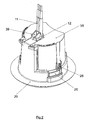
- the detector assembly 10 comprises two main components, a ceiling mountable base 20 and a plug in detector module 70.
- the base 20 has a body 22 defining a downwardly opening socket 23 and a mouth 24 within the socket 23 for receiving a portion of a backup battery 76.
- the base 20 is mountable in a ceiling through a circular cut out using mounting arms 25.
- Mounting arms 25 rotate about mounting screws 26.
- a cover 35 is mounted about a hinge 36 to double insulate the terminal area in the roof cavity.
- the top cover 35 includes a break out area 37 for up to three additional cables.
- Upright portion or post 39 is provided by body 22 to enable secure connection of the power supply cable using a cable tie 12 as is shown in Figures 1 and 12.
- the same post 39 forms the mouth 24 for receiving a portion of the battery 76.
- the body 22 of the base 20 defines an aperture 27 position adjacent the mouth 24.
- the aperture 27 provides a path for electrical connection between the detector module 70 and the base 20.
- a means of connecting the assembly 10 to mains electricity is provided by four terminals A E N I (Active, Earth, Neutral, Interconnect).
- the terminals are arranged in line making wiring easy as is shown in Figures 3, 9 and 12.
- the diameter of the terminals 31, 32, 33 and 34 is preferably five millimeters. Connection of wiring to these terminals is made easy by the fact that the top cover 35 can flip open 180 degrees giving clear access to the terminal area as is shown in Figure 3.
- terminal 31 comprises a body 36 that defines a cylindrical recess for receiving a mains wire and a screw 38 threadable received within a tapped hole through the body 36 into the cylindrical recess.
- a stud conductor 41 is also defined by the body 36. In use, the screw 38 clamps the wire in place within the cylindrical recess and power is transmitted from the wire into the body 36 and out through the stud conductor 41 to the detector module 70.
- the detector module 70 has a battery support portion 75 that holds the battery 76 in a vertical orientation extending away from and protruding from the body of the detector module 70.
- the battery may be mounted on its side with one side extending away from the body of the detector module.
- a quick connection means for mechanically and electrically connecting the detector module 70 to the base 20 is provided.
- the quick connection means comprises at least two cooperable pairs of conductors, in use the conductor pairs transmitting power from the base 20 to the detector module 70.
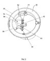
- the pairs of conductors are most clearly shown in Figures 12 and 13. They are mutually shaped and constructed so as to provide sufficient mechanical holding strength to support the module against gravity.
- quick connection means for mechanical connection and for electrical connection may be separate.
- each of the cooperable pairs of conductors comprises a stud conductor, such as the stud conductor 41 shown in Figure 13, and a forked conductor, such as a conductor 91 shown in the same Figure.
- Forked conductor 91 has a pair of spaced apart resilient prongs 91' that are biased towards each other and are disposed on opposite sides of the stud 41 thereby gripping the stud 41.
- the slot formed between each pair of prongs ensures that contact with the corresponding stud is achieved in spite of height differences arising from manufacturing tolerance variations.
- the lockout means is arranged to prevent operation of the above described connection means when no battery is installed within the detector module 70.
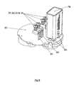
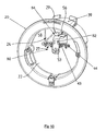
- the lockout means includes a shutter 50 mounted to the base 20 as shown in Figures 5, 10 and 11.
- the construction of the shutter is best seen in Figure 10.
- Figure 10 shows that the shutter includes a leg 54 having an upper end 56 connected to an upper end 29 of the mouth 24.
- a foot 53 is connected to the lower end 58 of the leg 54.
- the foot 53 has a blocking portion, the blocking portion extending over the aperture 27 so as to block the path through which the quick connection means operates when the shutter is in its closed position as shown in Figure 10. In this position, cut outs 52 are not aligned with the row of terminal studs 41, 42, 43 and 44 and therefore the central forked conductors 92 and 93 are mechanically blocked from engaging the studs 42 and 43.
- the shutter 50 is shaped and positioned such that when a battery 76 is installed in the detector module 70, as is shown in Figure 4, the battery 76 will displace it as the detector module 70 is inserted up into the base 20. This is best seen in the cutaway view of Figure 12.
- the upper part of the battery 76 engages the leg 54 of the shutter 50 before the top of the forked conductor 92 reaches the cut out area 52.
- the cut out area 52 is in the position shown in Figure 11 by the time the forked conductor 92 is about to pass through towards the terminal stud 42.
- electrical connection between the detector module 70 and the ceiling mountable base 20 is made via linear connection rather than by a plug in terminal or a rotating connection as is commonly used in other smoke detector systems.
- the printed circuit board 80 housed within the detector module 70 is shown in Figures 6, 7, 8 and 9.
- a sensor 82 is shown.
- the sensor 82 is a smoke sensor.
- a carbon monoxide or other type of detector may be fitted.
- a horn 84 is provided to produce a loud warning signal.
- Conventional red and green LEDs 85 and 86 are provided together with light pipes 105 and 106 (light pipes shown in Figures 4 and 6).
- a push-to-test button 102 is provided as shown in Figures 6 and 7.
- Figure 9 shows how the battery 76 simply engages battery contacts 81.
- the terminals 31, 32, 33 and 34 although shown in Figure 9 for clarity of illustration, are in fact located within the ceiling mountable base 20.
- Figure 9 shows how the terminal 31, 32, 33 and 34 engage with the contact tabs 91, 92, 93 and 94 when the detector module 70 is installed with a battery 76 within the ceiling mountable base 20.
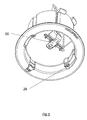
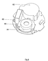
- FIG. 14 and 15 A second embodiment of the invention is shown in figures 14 and 15. This embodiment of the invention is similar to the first embodiment of the invention described above except for the lockout means.
- the lockout means for the second embodiment of the invention comprises a blocking member 120 pivotably mounted to the module 70 for rotation from a blocking position to a retracted position.
- the blocking member is shown in its blocking position in figure 14 and its retracted position in figure 15.
- the lockout means also comprises a biasing means in the form of a spring 128 positioned within recess 28 for biasing the blocking member 120 into its blocking position when no batteries are installed within the detector module as shown figure 14.
- the spring 128 is clearly shown in figure 15, but has been omitted from figure 14 for clarity.
- the battery contact 81 of the first embodiment of the invention has been replaced with standard snap connectors 181 as shown in figure 14. These snap connectors engage with the standard projecting spaced apart snap connectors mounted on the end face of a standard knife or battery.
- the blocking member 120 comprises an upwardly extending leg 122 joined to a foot 124, the foot having a battery face engaging portion 126 located adjacent snap connectors 181 of the battery support portion.
- the engaging portion 126 is displaced and held down by the face 77 of the battery 76 when the battery 76 is installed, thereby holding the blocking member 120 into its retracted position.
- the leg 122 of the blocking member 120 is adjacent and parallel to the battery 76 allowing it to enter the mouth within the base 20.
- the above described detector assemblies 10 both provide a compact low profile smoke detector that is easy to install by an electrical contractor.
Landscapes
- Physics & Mathematics (AREA)
- General Physics & Mathematics (AREA)
- Chemical & Material Sciences (AREA)
- Analytical Chemistry (AREA)
- Business, Economics & Management (AREA)
- Emergency Management (AREA)
- Engineering & Computer Science (AREA)
- Computer Security & Cryptography (AREA)
- Fire-Detection Mechanisms (AREA)
- Fire Alarms (AREA)
- Battery Mounting, Suspending (AREA)
Claims (12)
- Detektoranordnung, die durch Netzstrom und eine längliche Backup-Batterie gespeist wird, wobei die Anordnung Folgendes umfasst:eine deckenmontierbare Basis (20) mit: einem eine sich nach unten öffnende Fassung (23) definierenden Körper (22), einer Mündung (24) in der Fassung (23) zur Aufnahme eines Teils der Batterie (76) und einen Mittel zur Verbindung mit dem Netzstrom;ein Detektormodul (70) mit einem Batteriestützteil (75) zum Halten der Batterie in einer vertikalen Ausrichtung, wobei das Modul durch die Fassung aufgenommen werden kann;ein Schnellverbindungsmittel zur mechanischen Verbindung des Detektormoduls (70) mit der Basis (20);ein Schnellverbindungsmittel zur elektrischen Verbindung des Detektormoduls (70) mit der Basis (20); wobei die elektrische Verbindung Energie von dem Energieversorgungsmittel zum Modul (70) zuführt; undein Sperrmittel, das dazu angeordnet ist, eine Betätigung mindestens des mechanischen Schnellverbindungsmittels zu verhindern, wenn im Detektormodul keine Batterie installiert ist.
- Anordnung nach Anspruch 1, bei der das Sperrmittel Folgendes umfasst:ein Blockierglied (120), das schwenkbar am Modul zur Drehung aus einer Blockierposition in eine zurückgezogene Position angebracht ist; undein Vorspannmittel (128) zum Vorspannen des Blockierglieds (120) in seine Blockierposition, wenn keine Batterie (76) im Detektormodul (70) installiert ist.
- Anordnung nach Anspruch 2 zur Verwendung mit einer standardmäßigen Neun-Volt-Batterie mit einer Endfläche (77) mit einem Paar vorragender, beabstandeter Schnappverbinder,
wobei der Batteriestützteil (75) ein Paar standardmäßiger nach oben weisender Schnappverbinder (181) umfasst, die zur Ineingriffnahme der Schnappverbinder der Batterie angeordnet und ausgeführt sind. - Anordnung nach Anspruch 3, bei der das Blockierglied (120) einen sich nach oben erstreckenden Schenkel (122) umfasst, der mit einem Fuß (124) verbunden ist, wobei der Fuß (124) einen Batterieflächeneingriffsteil (126) aufweist, der neben den Schnappverbindern (181) des Batteriestützteils angeordnet ist,
wobei der Eingriffsteil (126) durch die Fläche (77) der Batterie (76) verschoben und nach unten gehalten wird, wenn die Batterie (76) installiert ist, wodurch das Blockierglied (120) in seiner zurückgezogenen Position gehalten wird. - Anordnung nach Anspruch 4, bei der das Vorspannmittel (128) eine Feder umfasst.
- Anordnung nach Anspruch 5, bei der das Mittel zur Verbindung mit dem Netzstrom mindestens zwei Anschlüsse (31 - 34) zur Aufnahme von elektrischer Verdrahtung umfasst.
- Anordnung nach einem der Ansprüche 1 bis 6, bei der jeder Anschluss (31 - 34) Folgendes umfasst:einen Körper (36), der eine zylindrische Aussparung zur Aufnahme eines Netzdrahtes und einen Stiftverbinder (41) definiert; undeine Schraube (38), die in einem Gewindeloch durch den Körper (36) in die zylindrische Aussparung in Gewindeaufnahme steht,wobei die Schraube (38) im Gebrauch den Draht in der zylindrischen Aussparung festklemmt und Energie von dem Draht in den Körper (36) und durch den Stift (41) heraus zum Modul übertragen wird.
- Anordnung nach Anspruch 7, bei der das Schnellverbindungsmittel mindestes zwei Leiterpaare, die zusammenwirken können, umfasst, wobei die Leiterpaare im Gebrauch Energie von der Basis zum Detektormodul übertragen, wobei die Leiterpaare jeweils Folgendes umfassen:den Stiftverbinder (41), undeinen am Modul (70) angebrachten gegabelten Leiter (91),wobei die Leiter gegenseitig so geformt und ausgeführt sind, dass sie eine ausreichende mechanische Haltekraft zum Abstützen des Moduls gegen Schwerkraft bereitstellen.
- Anordnung nach Anspruch 8, bei der jeder gegabelte Leiter zwei voneinander beabstandete elastische Zinken (91) umfasst, die zueinander vorgespannt sind, um den Stift (41) zu ergreifen.
- Anordnung nach Anspruch 9, bei der die gegabelten Leiter (91) aus Phosphorbronze hergestellt sind.
- Anordnung nach einem der Ansprüche 1 bis 10, bei der der Körper zur Definition einer Stütze (39) geformt ist, deren Innenseite die Mündung (24) bildet.
- Anordnung nach Anspruch 11, bei der die Stütze (39) eine Aussparung zur Aufnahme eines Kabelbinders zwecks Erleichterung des Haltens eines Netzstromkabels aufweist.
Priority Applications (1)
| Application Number | Priority Date | Filing Date | Title |
|---|---|---|---|
| EP06256058A EP1783711B1 (de) | 2002-12-18 | 2003-12-18 | Für Rauchalarme geeignete Detektorbaugruppe |
Applications Claiming Priority (3)
| Application Number | Priority Date | Filing Date | Title |
|---|---|---|---|
| AU2002953417 | 2002-12-18 | ||
| AU2002953417A AU2002953417A0 (en) | 2002-12-18 | 2002-12-18 | Detector assembly suited to smoke alarms |
| PCT/AU2003/001684 WO2004055750A1 (en) | 2002-12-18 | 2003-12-18 | Detector assembly suited to smoke alarms |
Related Child Applications (1)
| Application Number | Title | Priority Date | Filing Date |
|---|---|---|---|
| EP06256058A Division EP1783711B1 (de) | 2002-12-18 | 2003-12-18 | Für Rauchalarme geeignete Detektorbaugruppe |
Publications (4)
| Publication Number | Publication Date |
|---|---|
| EP1573696A1 EP1573696A1 (de) | 2005-09-14 |
| EP1573696A4 EP1573696A4 (de) | 2006-03-15 |
| EP1573696B1 EP1573696B1 (de) | 2007-07-11 |
| EP1573696B9 true EP1573696B9 (de) | 2007-11-28 |
Family
ID=30004502
Family Applications (2)
| Application Number | Title | Priority Date | Filing Date |
|---|---|---|---|
| EP06256058A Expired - Lifetime EP1783711B1 (de) | 2002-12-18 | 2003-12-18 | Für Rauchalarme geeignete Detektorbaugruppe |
| EP03779565A Expired - Lifetime EP1573696B9 (de) | 2002-12-18 | 2003-12-18 | Für rauchmelder geeignete detektorbaugruppe |
Family Applications Before (1)
| Application Number | Title | Priority Date | Filing Date |
|---|---|---|---|
| EP06256058A Expired - Lifetime EP1783711B1 (de) | 2002-12-18 | 2003-12-18 | Für Rauchalarme geeignete Detektorbaugruppe |
Country Status (14)
| Country | Link |
|---|---|
| US (1) | US7414538B2 (de) |
| EP (2) | EP1783711B1 (de) |
| CN (1) | CN100437652C (de) |
| AT (2) | ATE366974T1 (de) |
| AU (2) | AU2002953417A0 (de) |
| BR (1) | BR0317568A (de) |
| CA (1) | CA2510752A1 (de) |
| DE (2) | DE60314905D1 (de) |
| DK (1) | DK1573696T3 (de) |
| MX (1) | MXPA05006687A (de) |
| NZ (1) | NZ540253A (de) |
| SG (1) | SG174725A1 (de) |
| WO (1) | WO2004055750A1 (de) |
| ZA (1) | ZA200505729B (de) |
Families Citing this family (27)
| Publication number | Priority date | Publication date | Assignee | Title |
|---|---|---|---|---|
| DE10353836A1 (de) | 2003-11-18 | 2005-06-09 | Robert Bosch Gmbh | Brandmelder |
| GB0506671D0 (en) * | 2005-04-01 | 2005-05-11 | Fireangel Ltd | Alarm |
| AU2011203296B2 (en) * | 2005-05-10 | 2013-09-26 | Hochiki Corporation | Sounder |
| CN101171616A (zh) | 2005-05-10 | 2008-04-30 | 报知机股份有限公司 | 发声器 |
| AU2011203306B2 (en) * | 2005-05-10 | 2011-11-03 | Hochiki Corporation | Sounder |
| AU2011203307B2 (en) * | 2005-05-10 | 2013-08-22 | Hochiki Corporation | Sounder |
| AU2005100740B4 (en) * | 2005-09-09 | 2005-12-22 | Firetronics Pty Ltd | Semi countersunk smoke detector |
| US20110210854A1 (en) * | 2009-12-31 | 2011-09-01 | Chris Kelly | Building safety detector assembly |
| PL392067A1 (pl) * | 2010-08-05 | 2012-02-13 | Diehl Ako Stiftung & Co. Kg | Sygnalizator dymu z mechanizmem zabezpieczającym |
| CA143371S (en) * | 2011-11-23 | 2012-10-15 | Cavius Aps | Smoke sensor |
| CA147547S (en) | 2012-08-27 | 2013-04-19 | Cavius Aps | Heat detector |
| ES2451915R1 (es) | 2012-09-27 | 2014-06-02 | Utc Fire & Security Americas Corporation, Inc. | Sistema modular de detección de humo y procedimiento para montar un sistema de detección de humo |
| USD758230S1 (en) | 2013-09-05 | 2016-06-07 | Cavius Aps | Smoke alarm |
| US20150130621A1 (en) * | 2013-10-21 | 2015-05-14 | Ronald F. Seiler | Remotely Installed Fires & Smoke Detector |
| USD769756S1 (en) | 2014-01-30 | 2016-10-25 | Cavius Aps | Heat detector |
| DE102015004458B4 (de) | 2014-06-26 | 2016-05-12 | Elmos Semiconductor Aktiengesellschaft | Vorrichtung und Verfahren für einen klassifizierenden, rauchkammerlosen Luftzustandssensor zur Prognostizierung eines folgenden Betriebszustands |
| DE102014019773B4 (de) | 2014-12-17 | 2023-12-07 | Elmos Semiconductor Se | Vorrichtung und Verfahren zur Unterscheidung von festen Objekten, Kochdunst und Rauch mittels des Displays eines Mobiltelefons |
| DE102014019172B4 (de) | 2014-12-17 | 2023-12-07 | Elmos Semiconductor Se | Vorrichtung und Verfahren zur Unterscheidung von festen Objekten, Kochdunst und Rauch mit einem kompensierenden optischen Messsystem |
| USD820709S1 (en) * | 2015-04-01 | 2018-06-19 | Xtralis Global | Flange of a sampling point assembly |
| US10222079B2 (en) * | 2015-06-10 | 2019-03-05 | British Gas Trading Limited | Battery-powered control device |
| US10600299B2 (en) * | 2015-10-15 | 2020-03-24 | Steven Benjamin Faubion | Smoke detector with removable battery compartment |
| CN105608830B (zh) * | 2016-03-15 | 2017-12-12 | 宁波市乐星感应电器有限公司 | 一种新型结构的烟雾报警器 |
| KR101911371B1 (ko) * | 2018-04-20 | 2018-10-25 | 윈텍정보(주) | 부가기능 확장형 화재감지기 |
| CN113870511A (zh) * | 2020-06-30 | 2021-12-31 | 宝武装备智能科技有限公司 | 用于电源插线板的火灾报警装置 |
| CN116526202A (zh) * | 2022-01-24 | 2023-08-01 | 郑州万马云电子科技有限公司 | 吸顶式基站 |
| US20240337640A1 (en) * | 2023-04-07 | 2024-10-10 | Carrier Corporation | Replaceable module for a gas detector |
| CN116154568B (zh) * | 2023-04-20 | 2023-06-20 | 深圳市誉铭旺电子股份有限公司 | 一种感温探测器线缆装置 |
Family Cites Families (18)
| Publication number | Priority date | Publication date | Assignee | Title |
|---|---|---|---|---|
| US4257039A (en) * | 1978-12-26 | 1981-03-17 | Norma J. Webb | Smoke detector |
| US4870395A (en) * | 1988-03-10 | 1989-09-26 | Seatt Corporation | Battery powered smoke alarm safety lockout system |
| GB2221331A (en) * | 1988-07-28 | 1990-01-31 | John Edward Kingston | Smoke detector |
| US4881063A (en) * | 1989-01-30 | 1989-11-14 | Ei Company, Ltd. | Battery removal indicator |
| US4959640A (en) * | 1989-03-09 | 1990-09-25 | Pioneer Manufacturing, Inc. | Apparatus for detect missing battery in smoke detector |
| US5103216A (en) * | 1989-06-12 | 1992-04-07 | Pittway Corporation | Improperly inserted battery detector |
| JP2606954B2 (ja) * | 1990-08-30 | 1997-05-07 | シャープ株式会社 | 電池の収納構造 |
| US5280273A (en) * | 1992-12-21 | 1994-01-18 | Goldstein Mark K | Toxic gas detector system having convenient battery and sensor replacement |
| CH685410A5 (de) * | 1993-02-15 | 1995-06-30 | Cerberus Ag | Vorrichtung zur Funktionsprüfung von Rauchmeldern. |
| GB9307187D0 (en) * | 1993-04-06 | 1993-05-26 | Dee Electronics Limited | Gas alarm |
| US5596314A (en) * | 1994-08-01 | 1997-01-21 | Quantum Group, Inc. | Enclosure for a gas detector system |
| US5820406A (en) * | 1996-07-29 | 1998-10-13 | Hetherington; Michael Warnett | Terminal and door latch for battery operated devices |
| AU749397B2 (en) * | 1997-01-17 | 2002-06-27 | Shane Eric Bessell | Smoke detector assembly |
| DE69810103D1 (de) * | 1998-08-25 | 2003-01-23 | Lucent Technologies Inc | Stromversorgungsmodul |
| IE990427A1 (en) * | 1999-04-13 | 2000-11-15 | E I Technology Ltd | An Alarm Device |
| US6172612B1 (en) * | 1999-06-04 | 2001-01-09 | Mark Odachowski | Smoke detector with remote testing, shutoff and powering means |
| US6160487A (en) * | 1999-07-22 | 2000-12-12 | Kidde Walter Portable Equipment Inc | Single lockout mechanism for a multiple battery compartment that is particularly suited for smoke and carbon monoxide detector apparatus |
| GB2371666A (en) * | 2001-01-25 | 2002-07-31 | James Turner | Fire alarm and light fitting |
-
2002
- 2002-12-18 AU AU2002953417A patent/AU2002953417A0/en not_active Abandoned
-
2003
- 2003-12-18 WO PCT/AU2003/001684 patent/WO2004055750A1/en not_active Ceased
- 2003-12-18 NZ NZ540253A patent/NZ540253A/en not_active IP Right Cessation
- 2003-12-18 DK DK03779565T patent/DK1573696T3/da active
- 2003-12-18 EP EP06256058A patent/EP1783711B1/de not_active Expired - Lifetime
- 2003-12-18 SG SG2011040987A patent/SG174725A1/en unknown
- 2003-12-18 MX MXPA05006687A patent/MXPA05006687A/es active IP Right Grant
- 2003-12-18 US US10/539,263 patent/US7414538B2/en not_active Expired - Fee Related
- 2003-12-18 ZA ZA200505729A patent/ZA200505729B/en unknown
- 2003-12-18 EP EP03779565A patent/EP1573696B9/de not_active Expired - Lifetime
- 2003-12-18 CA CA002510752A patent/CA2510752A1/en not_active Abandoned
- 2003-12-18 AU AU2003287769A patent/AU2003287769B2/en not_active Ceased
- 2003-12-18 DE DE60314905T patent/DE60314905D1/de not_active Expired - Lifetime
- 2003-12-18 AT AT03779565T patent/ATE366974T1/de not_active IP Right Cessation
- 2003-12-18 BR BR0317568-5A patent/BR0317568A/pt not_active Application Discontinuation
- 2003-12-18 AT AT06256058T patent/ATE409933T1/de not_active IP Right Cessation
- 2003-12-18 CN CNB2003801071019A patent/CN100437652C/zh not_active Expired - Fee Related
- 2003-12-18 DE DE60323887T patent/DE60323887D1/de not_active Expired - Fee Related
Also Published As
| Publication number | Publication date |
|---|---|
| CN1729492A (zh) | 2006-02-01 |
| HK1082834A1 (en) | 2006-06-16 |
| SG174725A1 (en) | 2011-10-28 |
| AU2003287769B2 (en) | 2008-05-29 |
| EP1783711B1 (de) | 2008-10-01 |
| AU2003287769A1 (en) | 2004-07-09 |
| DE60314905D1 (de) | 2007-08-23 |
| ATE409933T1 (de) | 2008-10-15 |
| BR0317568A (pt) | 2005-11-22 |
| US7414538B2 (en) | 2008-08-19 |
| AU2002953417A0 (en) | 2003-01-09 |
| CN100437652C (zh) | 2008-11-26 |
| MXPA05006687A (es) | 2006-02-22 |
| ZA200505729B (en) | 2007-01-31 |
| EP1573696B1 (de) | 2007-07-11 |
| EP1573696A4 (de) | 2006-03-15 |
| EP1783711A1 (de) | 2007-05-09 |
| ATE366974T1 (de) | 2007-08-15 |
| DK1573696T3 (da) | 2007-11-05 |
| CA2510752A1 (en) | 2004-07-01 |
| WO2004055750A1 (en) | 2004-07-01 |
| NZ540253A (en) | 2007-01-26 |
| DE60323887D1 (de) | 2008-11-13 |
| EP1573696A1 (de) | 2005-09-14 |
| US20060202849A1 (en) | 2006-09-14 |
Similar Documents
| Publication | Publication Date | Title |
|---|---|---|
| EP1573696B9 (de) | Für rauchmelder geeignete detektorbaugruppe | |
| US9997860B1 (en) | Coverplate and method for electrical outlet | |
| US5418521A (en) | Power cable with alarm | |
| US20030092297A1 (en) | Convenience light with supplemental electrical outlet | |
| US6036536A (en) | Different features in the structure of an electrical outlet | |
| CN100413158C (zh) | 带有万向支架安装的传感器的转接器 | |
| US20070103330A1 (en) | Remotely located battery for a smoke detector | |
| AU2008100363A4 (en) | Detector assembly suited to smoke alarms | |
| EP1045354B1 (de) | Alarmvorrichtung | |
| JP3324016B2 (ja) | 火災報知設備の中継器 | |
| US20010046815A1 (en) | Method of providing electrical energy to devices without using prongs | |
| HK1082834B (en) | Detector assembly suited to smoke alarms | |
| HK1100234A (en) | Detector assembly suited to smoke alarms | |
| GB2312312A (en) | A mains powered alarm sensor unit having a primary battery backup | |
| US3908103A (en) | Combined outlet and safety switch unit with adapter | |
| US11171447B2 (en) | Plug and socket assemblies that operatively associate by way of a safety locking mechanism for facilitating plugging and unplugging of electrical fixtures | |
| JP3243280B2 (ja) | 配線装置 | |
| KR100436880B1 (ko) | 누전차단기가 장착된 콘센트 | |
| CN223679963U (zh) | 按钮开关及插排 | |
| AU2004298121B2 (en) | Improvements in and relating to electrical power, communication and data cable management systems | |
| JPH0529026A (ja) | ハーネスプラグ | |
| IE960718A1 (en) | A mains powered alarm sensor unit having a primary battery backup | |
| JPH0529027A (ja) | ハーネスコネクタ | |
| JP2002150445A (ja) | 火災報知設備 | |
| JP2004021653A (ja) | 警報器の取り付けベース |
Legal Events
| Date | Code | Title | Description |
|---|---|---|---|
| PUAI | Public reference made under article 153(3) epc to a published international application that has entered the european phase |
Free format text: ORIGINAL CODE: 0009012 |
|
| 17P | Request for examination filed |
Effective date: 20050622 |
|
| AK | Designated contracting states |
Kind code of ref document: A1 Designated state(s): AT BE BG CH CY CZ DE DK EE ES FI FR GB GR HU IE IT LI LU MC NL PT RO SE SI SK TR |
|
| AX | Request for extension of the european patent |
Extension state: AL LT LV MK |
|
| A4 | Supplementary search report drawn up and despatched |
Effective date: 20060201 |
|
| DAX | Request for extension of the european patent (deleted) | ||
| REG | Reference to a national code |
Ref country code: HK Ref legal event code: DE Ref document number: 1082834 Country of ref document: HK |
|
| GRAP | Despatch of communication of intention to grant a patent |
Free format text: ORIGINAL CODE: EPIDOSNIGR1 |
|
| RAP1 | Party data changed (applicant data changed or rights of an application transferred) |
Owner name: CLIPSAL AUSTRALIA PTY LTD. |
|
| GRAS | Grant fee paid |
Free format text: ORIGINAL CODE: EPIDOSNIGR3 |
|
| GRAA | (expected) grant |
Free format text: ORIGINAL CODE: 0009210 |
|
| AK | Designated contracting states |
Kind code of ref document: B1 Designated state(s): AT BE BG CH CY CZ DE DK EE ES FI FR GB GR HU IE IT LI LU MC NL PT RO SE SI SK TR |
|
| REG | Reference to a national code |
Ref country code: GB Ref legal event code: FG4D |
|
| REG | Reference to a national code |
Ref country code: CH Ref legal event code: EP |
|
| REF | Corresponds to: |
Ref document number: 60314905 Country of ref document: DE Date of ref document: 20070823 Kind code of ref document: P |
|
| REG | Reference to a national code |
Ref country code: IE Ref legal event code: FG4D |
|
| REG | Reference to a national code |
Ref country code: SE Ref legal event code: TRGR |
|
| REG | Reference to a national code |
Ref country code: HK Ref legal event code: GR Ref document number: 1082834 Country of ref document: HK |
|
| REG | Reference to a national code |
Ref country code: DK Ref legal event code: T3 |
|
| ET | Fr: translation filed | ||
| PG25 | Lapsed in a contracting state [announced via postgrant information from national office to epo] |
Ref country code: PT Free format text: LAPSE BECAUSE OF FAILURE TO SUBMIT A TRANSLATION OF THE DESCRIPTION OR TO PAY THE FEE WITHIN THE PRESCRIBED TIME-LIMIT Effective date: 20071211 Ref country code: ES Free format text: LAPSE BECAUSE OF FAILURE TO SUBMIT A TRANSLATION OF THE DESCRIPTION OR TO PAY THE FEE WITHIN THE PRESCRIBED TIME-LIMIT Effective date: 20071022 Ref country code: BG Free format text: LAPSE BECAUSE OF FAILURE TO SUBMIT A TRANSLATION OF THE DESCRIPTION OR TO PAY THE FEE WITHIN THE PRESCRIBED TIME-LIMIT Effective date: 20071011 Ref country code: FI Free format text: LAPSE BECAUSE OF FAILURE TO SUBMIT A TRANSLATION OF THE DESCRIPTION OR TO PAY THE FEE WITHIN THE PRESCRIBED TIME-LIMIT Effective date: 20070711 |
|
| PG25 | Lapsed in a contracting state [announced via postgrant information from national office to epo] |
Ref country code: AT Free format text: LAPSE BECAUSE OF FAILURE TO SUBMIT A TRANSLATION OF THE DESCRIPTION OR TO PAY THE FEE WITHIN THE PRESCRIBED TIME-LIMIT Effective date: 20070711 |
|
| PG25 | Lapsed in a contracting state [announced via postgrant information from national office to epo] |
Ref country code: BE Free format text: LAPSE BECAUSE OF FAILURE TO SUBMIT A TRANSLATION OF THE DESCRIPTION OR TO PAY THE FEE WITHIN THE PRESCRIBED TIME-LIMIT Effective date: 20070711 |
|
| PG25 | Lapsed in a contracting state [announced via postgrant information from national office to epo] |
Ref country code: GR Free format text: LAPSE BECAUSE OF FAILURE TO SUBMIT A TRANSLATION OF THE DESCRIPTION OR TO PAY THE FEE WITHIN THE PRESCRIBED TIME-LIMIT Effective date: 20071012 |
|
| PLBE | No opposition filed within time limit |
Free format text: ORIGINAL CODE: 0009261 |
|
| STAA | Information on the status of an ep patent application or granted ep patent |
Free format text: STATUS: NO OPPOSITION FILED WITHIN TIME LIMIT |
|
| PG25 | Lapsed in a contracting state [announced via postgrant information from national office to epo] |
Ref country code: CZ Free format text: LAPSE BECAUSE OF FAILURE TO SUBMIT A TRANSLATION OF THE DESCRIPTION OR TO PAY THE FEE WITHIN THE PRESCRIBED TIME-LIMIT Effective date: 20070711 Ref country code: SK Free format text: LAPSE BECAUSE OF FAILURE TO SUBMIT A TRANSLATION OF THE DESCRIPTION OR TO PAY THE FEE WITHIN THE PRESCRIBED TIME-LIMIT Effective date: 20070711 |
|
| 26N | No opposition filed |
Effective date: 20080414 |
|
| PG25 | Lapsed in a contracting state [announced via postgrant information from national office to epo] |
Ref country code: RO Free format text: LAPSE BECAUSE OF FAILURE TO SUBMIT A TRANSLATION OF THE DESCRIPTION OR TO PAY THE FEE WITHIN THE PRESCRIBED TIME-LIMIT Effective date: 20070711 |
|
| PG25 | Lapsed in a contracting state [announced via postgrant information from national office to epo] |
Ref country code: DE Free format text: LAPSE BECAUSE OF FAILURE TO SUBMIT A TRANSLATION OF THE DESCRIPTION OR TO PAY THE FEE WITHIN THE PRESCRIBED TIME-LIMIT Effective date: 20071012 Ref country code: MC Free format text: LAPSE BECAUSE OF NON-PAYMENT OF DUE FEES Effective date: 20071231 |
|
| REG | Reference to a national code |
Ref country code: CH Ref legal event code: NV Representative=s name: BUGNION S.A. |
|
| PG25 | Lapsed in a contracting state [announced via postgrant information from national office to epo] |
Ref country code: IE Free format text: LAPSE BECAUSE OF NON-PAYMENT OF DUE FEES Effective date: 20071218 |
|
| PG25 | Lapsed in a contracting state [announced via postgrant information from national office to epo] |
Ref country code: EE Free format text: LAPSE BECAUSE OF FAILURE TO SUBMIT A TRANSLATION OF THE DESCRIPTION OR TO PAY THE FEE WITHIN THE PRESCRIBED TIME-LIMIT Effective date: 20070711 |
|
| PG25 | Lapsed in a contracting state [announced via postgrant information from national office to epo] |
Ref country code: SI Free format text: LAPSE BECAUSE OF FAILURE TO SUBMIT A TRANSLATION OF THE DESCRIPTION OR TO PAY THE FEE WITHIN THE PRESCRIBED TIME-LIMIT Effective date: 20070711 |
|
| PG25 | Lapsed in a contracting state [announced via postgrant information from national office to epo] |
Ref country code: CY Free format text: LAPSE BECAUSE OF FAILURE TO SUBMIT A TRANSLATION OF THE DESCRIPTION OR TO PAY THE FEE WITHIN THE PRESCRIBED TIME-LIMIT Effective date: 20070711 |
|
| PG25 | Lapsed in a contracting state [announced via postgrant information from national office to epo] |
Ref country code: LU Free format text: LAPSE BECAUSE OF NON-PAYMENT OF DUE FEES Effective date: 20071218 |
|
| PG25 | Lapsed in a contracting state [announced via postgrant information from national office to epo] |
Ref country code: HU Free format text: LAPSE BECAUSE OF FAILURE TO SUBMIT A TRANSLATION OF THE DESCRIPTION OR TO PAY THE FEE WITHIN THE PRESCRIBED TIME-LIMIT Effective date: 20080112 Ref country code: TR Free format text: LAPSE BECAUSE OF FAILURE TO SUBMIT A TRANSLATION OF THE DESCRIPTION OR TO PAY THE FEE WITHIN THE PRESCRIBED TIME-LIMIT Effective date: 20070711 |
|
| PG25 | Lapsed in a contracting state [announced via postgrant information from national office to epo] |
Ref country code: IT Free format text: LAPSE BECAUSE OF NON-PAYMENT OF DUE FEES Effective date: 20071231 |
|
| REG | Reference to a national code |
Ref country code: FR Ref legal event code: PLFP Year of fee payment: 13 |
|
| REG | Reference to a national code |
Ref country code: FR Ref legal event code: PLFP Year of fee payment: 14 |
|
| PGFP | Annual fee paid to national office [announced via postgrant information from national office to epo] |
Ref country code: GB Payment date: 20161214 Year of fee payment: 14 Ref country code: FR Payment date: 20161111 Year of fee payment: 14 Ref country code: NL Payment date: 20161212 Year of fee payment: 14 Ref country code: DK Payment date: 20161212 Year of fee payment: 14 Ref country code: CH Payment date: 20161213 Year of fee payment: 14 |
|
| PGFP | Annual fee paid to national office [announced via postgrant information from national office to epo] |
Ref country code: SE Payment date: 20161213 Year of fee payment: 14 |
|
| REG | Reference to a national code |
Ref country code: DK Ref legal event code: EBP Effective date: 20171231 |
|
| REG | Reference to a national code |
Ref country code: CH Ref legal event code: PL |
|
| REG | Reference to a national code |
Ref country code: NL Ref legal event code: MM Effective date: 20180101 |
|
| GBPC | Gb: european patent ceased through non-payment of renewal fee |
Effective date: 20171218 |
|
| PG25 | Lapsed in a contracting state [announced via postgrant information from national office to epo] |
Ref country code: SE Free format text: LAPSE BECAUSE OF NON-PAYMENT OF DUE FEES Effective date: 20171219 |
|
| PG25 | Lapsed in a contracting state [announced via postgrant information from national office to epo] |
Ref country code: NL Free format text: LAPSE BECAUSE OF NON-PAYMENT OF DUE FEES Effective date: 20180101 |
|
| REG | Reference to a national code |
Ref country code: FR Ref legal event code: ST Effective date: 20180831 |
|
| PG25 | Lapsed in a contracting state [announced via postgrant information from national office to epo] |
Ref country code: FR Free format text: LAPSE BECAUSE OF NON-PAYMENT OF DUE FEES Effective date: 20180102 |
|
| PG25 | Lapsed in a contracting state [announced via postgrant information from national office to epo] |
Ref country code: GB Free format text: LAPSE BECAUSE OF NON-PAYMENT OF DUE FEES Effective date: 20171218 Ref country code: LI Free format text: LAPSE BECAUSE OF NON-PAYMENT OF DUE FEES Effective date: 20171231 Ref country code: CH Free format text: LAPSE BECAUSE OF NON-PAYMENT OF DUE FEES Effective date: 20171231 |
|
| PG25 | Lapsed in a contracting state [announced via postgrant information from national office to epo] |
Ref country code: DK Free format text: LAPSE BECAUSE OF NON-PAYMENT OF DUE FEES Effective date: 20171231 |