EP1573863B1 - Modulare vorrichtung und verfahren zu der datenübertragung zwischen einem datenverteilungsnetzwerk und einem heimischen telekommunikationsnetzwerk - Google Patents
Modulare vorrichtung und verfahren zu der datenübertragung zwischen einem datenverteilungsnetzwerk und einem heimischen telekommunikationsnetzwerk Download PDFInfo
- Publication number
- EP1573863B1 EP1573863B1 EP02793064A EP02793064A EP1573863B1 EP 1573863 B1 EP1573863 B1 EP 1573863B1 EP 02793064 A EP02793064 A EP 02793064A EP 02793064 A EP02793064 A EP 02793064A EP 1573863 B1 EP1573863 B1 EP 1573863B1
- Authority
- EP
- European Patent Office
- Prior art keywords
- locking element
- devices
- network
- operative position
- modules
- Prior art date
- Legal status (The legal status is an assumption and is not a legal conclusion. Google has not performed a legal analysis and makes no representation as to the accuracy of the status listed.)
- Expired - Lifetime
Links
- 238000004891 communication Methods 0.000 title claims description 65
- 238000009826 distribution Methods 0.000 title claims description 24
- 238000000034 method Methods 0.000 title claims description 9
- 230000003213 activating effect Effects 0.000 claims description 11
- 238000012360 testing method Methods 0.000 claims description 8
- 230000000875 corresponding effect Effects 0.000 description 6
- 238000005516 engineering process Methods 0.000 description 6
- 230000004913 activation Effects 0.000 description 3
- 230000006870 function Effects 0.000 description 3
- 230000015654 memory Effects 0.000 description 3
- 230000003287 optical effect Effects 0.000 description 3
- 238000009423 ventilation Methods 0.000 description 3
- 101150012579 ADSL gene Proteins 0.000 description 2
- 102100020775 Adenylosuccinate lyase Human genes 0.000 description 2
- 108700040193 Adenylosuccinate lyases Proteins 0.000 description 2
- 230000002596 correlated effect Effects 0.000 description 2
- 230000000694 effects Effects 0.000 description 2
- 230000006855 networking Effects 0.000 description 2
- 238000012546 transfer Methods 0.000 description 2
- 239000004676 acrylonitrile butadiene styrene Substances 0.000 description 1
- 230000009471 action Effects 0.000 description 1
- 230000008878 coupling Effects 0.000 description 1
- 238000010168 coupling process Methods 0.000 description 1
- 238000005859 coupling reaction Methods 0.000 description 1
- 230000009849 deactivation Effects 0.000 description 1
- 238000013461 design Methods 0.000 description 1
- 238000004519 manufacturing process Methods 0.000 description 1
- 239000000463 material Substances 0.000 description 1
- 238000012986 modification Methods 0.000 description 1
- 230000004048 modification Effects 0.000 description 1
- 238000005457 optimization Methods 0.000 description 1
- 230000003094 perturbing effect Effects 0.000 description 1
- 239000004033 plastic Substances 0.000 description 1
- 229920003023 plastic Polymers 0.000 description 1
- 239000004417 polycarbonate Substances 0.000 description 1
- 229920000515 polycarbonate Polymers 0.000 description 1
- 230000000087 stabilizing effect Effects 0.000 description 1
Images
Classifications
-
- H—ELECTRICITY
- H04—ELECTRIC COMMUNICATION TECHNIQUE
- H04L—TRANSMISSION OF DIGITAL INFORMATION, e.g. TELEGRAPHIC COMMUNICATION
- H04L12/00—Data switching networks
- H04L12/28—Data switching networks characterised by path configuration, e.g. LAN [Local Area Networks] or WAN [Wide Area Networks]
- H04L12/2854—Wide area networks, e.g. public data networks
- H04L12/2856—Access arrangements, e.g. Internet access
- H04L12/2869—Operational details of access network equipments
- H04L12/2898—Subscriber equipments
-
- H—ELECTRICITY
- H01—ELECTRIC ELEMENTS
- H01R—ELECTRICALLY-CONDUCTIVE CONNECTIONS; STRUCTURAL ASSOCIATIONS OF A PLURALITY OF MUTUALLY-INSULATED ELECTRICAL CONNECTING ELEMENTS; COUPLING DEVICES; CURRENT COLLECTORS
- H01R13/00—Details of coupling devices of the kinds covered by groups H01R12/70 or H01R24/00 - H01R33/00
- H01R13/46—Bases; Cases
- H01R13/514—Bases; Cases composed as a modular blocks or assembly, i.e. composed of co-operating parts provided with contact members or holding contact members between them
-
- H—ELECTRICITY
- H01—ELECTRIC ELEMENTS
- H01R—ELECTRICALLY-CONDUCTIVE CONNECTIONS; STRUCTURAL ASSOCIATIONS OF A PLURALITY OF MUTUALLY-INSULATED ELECTRICAL CONNECTING ELEMENTS; COUPLING DEVICES; CURRENT COLLECTORS
- H01R13/00—Details of coupling devices of the kinds covered by groups H01R12/70 or H01R24/00 - H01R33/00
- H01R13/66—Structural association with built-in electrical component
- H01R13/70—Structural association with built-in electrical component with built-in switch
- H01R13/701—Structural association with built-in electrical component with built-in switch the switch being actuated by an accessory, e.g. cover, locking member
-
- H—ELECTRICITY
- H04—ELECTRIC COMMUNICATION TECHNIQUE
- H04L—TRANSMISSION OF DIGITAL INFORMATION, e.g. TELEGRAPHIC COMMUNICATION
- H04L12/00—Data switching networks
- H04L12/02—Details
- H04L12/10—Current supply arrangements
-
- Y—GENERAL TAGGING OF NEW TECHNOLOGICAL DEVELOPMENTS; GENERAL TAGGING OF CROSS-SECTIONAL TECHNOLOGIES SPANNING OVER SEVERAL SECTIONS OF THE IPC; TECHNICAL SUBJECTS COVERED BY FORMER USPC CROSS-REFERENCE ART COLLECTIONS [XRACs] AND DIGESTS
- Y10—TECHNICAL SUBJECTS COVERED BY FORMER USPC
- Y10S—TECHNICAL SUBJECTS COVERED BY FORMER USPC CROSS-REFERENCE ART COLLECTIONS [XRACs] AND DIGESTS
- Y10S439/00—Electrical connectors
- Y10S439/928—Modular electrically interengaging parts, e.g. stove with replaceable heating elements formed on coupling parts
Definitions
- the present invention relates to a modular apparatus and method for data communication between a distribution network and a residential network. More generally, the invention relates to a modular apparatus and method for allowing bi-directional data communication between a plurality of heterogeneous communication networks, and a local communication network allowing to interconnect residential appliances comprising a modular apparatus as above defined.
- the term “data” will be used to generally indicate those information or signals which are typically transmitted over a network, such as computer data, voice and video signals, etc.
- the term “distribution network” will be used to generally indicate a network adapted to transfer data to one or more narrower network
- the term “residential network” will be used to indicate a network adapted to receive data from a wider network and to transfer these data, directly or by interposition of narrower local networks, to a plurality of appliances, such as computers, printers, faxes, photocopying machines, television sets, telephones, etc.
- the term "distribution network” will be used to indicate, preferably, a wide area network (WAN) or any other type of external or metropolitan network
- the term "residential network” will be used to indicate, preferably, a local area network (LAN) or any other type of in-home network (such as that or those of residential or business settings).
- WAN wide area network
- LAN local area network
- the data communication between the distribution network and the residential network is bi-directional.
- WAN wide area network
- LAN local area networks
- appropriate systems are needed within the residential or business settings to provide a bridging (or routing, or gateway) function between the external or wide area network and one or more in-home or local area networks, thus allowing data distribution to different kinds of residential or business appliances, such as computers, printers, faxes, photocopying machines, television sets, telephones, etc.. It is very likely that this need will be always increasing in the future as new networking technologies will be discovered.
- gateway systems provide simultaneous access to multiple types of WANs or LANs using any of a variety of communication protocols.
- these systems are modular systems which are capable of accepting additional modules as desired by the user, and the modules are capable of transferring data to and from other modules.
- US patent application No. US 2002/0065935 A1 discloses a scalable modular gateway capable of communicating computer data, as well as voice and video services, between a variety of heterogeneous communication networks using any of a variety of communication protocols.
- the modular communication system includes at least two modules forming a stack.
- a first module interfaces a metropolitan distribution network (WAN) and a second module interfaces at least one residential network (LAN).
- WAN metropolitan distribution network
- LAN residential network
- Stacking pegs assist the proper.alignment of the modules when stacked together.
- the modules communicate with each other using connectors which are mated when the modules are stacked together. Communications buses allow data communication between the modules.
- the Applicant has realized that the current available gateways, as the one disclosed in the above identified patent application, suffers of some limitations and drawbacks.
- One of these is correlated to the possibility of damaging either the WAN or LAN or appliances connected thereto by permitting electrical and data communication between the modules even when these modules are not correctly and stably connected to each other, or by permitting the user to intentionally or accidentally interconnect modules which are not functionally fully compatible to each other, for example because they come from different manufactures.
- Another drawback is correlated to the possibility of transmitting corrupted or erroneous information, perturbing the WAN and/or LAN or temporarily making unavailable one of the services (such as telephony) linked to the LAN or the WAN.
- the Applicant has realized that to ensure high performance of the gateway and avoiding that the same gateway be damaged by intention or accident, or even that the WAN or LAN or appliances connected to the gateway be damaged, it is highly advisable at first to achieve a stable and correct mechanical and electrical connection between the modules and secondly to activate the electrical supply between the modules only when this stable and correct mechanical and electrical connection is achieved. Data communication between the modules is enabled only after each module is electrically supplied.
- the present invention relates, in a first aspect thereof, to a modular apparatus for data communication between a distribution network and a residential network, comprising according to claim 1.
- gateways any kind of apparatus which connect a distribution network and a residential network to each other, such as gateways, bridges, routers, etc..
- the invention relates to a modular apparatus capable of allowing data communication between a variety of different networks connected thereto (for example between a WAN and a LAN) through a plurality of devices (modules).
- the apparatus of the invention allows achieving high performance of the communication system and avoiding damaging by intention or accident of the same apparatus, or even of the networks or appliances connected thereto, by accomplishing and keeping a stable and correct mechanical and electrical connection between the devices or modules. More advantageously, this is achieved by providing an interconnecting device or lock which carries out both the functions of locking these modules to each other once connected (thus achieving and keeping over the time a stable and correct mechanical and electrical connection between the modules) and activating the electrical supply between the modules only when these modules are locked to each other. Therefore, the interconnecting device of the apparatus of this invention prevents powering of the expansion modules and this prevents data communication between the modules when these are not stably and correctly connected to each other, thus preserving the same modules, the networks and the appliances from possible damages.
- said at least interconnecting device is adapted to mate-with appropriate seats provided on said first and second devices, thus advantageously preventing the user from accidentally or voluntarily interconnecting modules which are not structurally and functionally fully compatible to each other and which therefore could cause the above mentioned damages (such as modules coming from different manufactures).
- the apparatus of the invention interfaces the WAN or external network through the first device (base module) by xDSL (e.g., ADSL) or optical technology.
- the base module receives the data from the WAN and routes these to different LANs or directly to different appliances through the other devices (expansion modules) of the apparatus.
- said first device also interfaces a local network so that, if only one module is needed to transmit data to the appliances of the residential setting, the apparatus consists of only the first device.
- the modular design of the apparatus of the invention advantageously has a variable geometrical configuration capable of accepting additional modules as the customer requires and as new networking technologies are discovered.
- the apparatus of the invention is not a fixed-size apparatus and may grow in capability as the customer requires and as new communications technologies are created.
- the manufacturing cost of the apparatus is therefore somehow proportionate to the number of modules and type of in-home networks needed, that means a very low initial cost if only few modules are required to supply data to the residential appliances, such.cost increasing only as new technologies evolve and new modules are required.
- said first and at least one second devices are mechanically and electrically connected to each other in a stack and said at least one interconnecting device is operatively interposed between said first and at least one second devices.
- the stack is a vertical stack and connectors for electrical connection and data communication between the modules are provided along a vertical direction so that they do not project out of the gateway when the modules are stacked together. This configuration advantageously allows to achieve space-optimization and aestethical value within the residential setting. However, even if less preferred, horizontal stack and other forms and shapes of module interconnection are also possible without affecting the operation and the main inventive aspects of the apparatus of this invention.
- said at least one interconnecting device defines a first operative configuration wherein said first and at least one second devices are unlocked so as to be disconnectable from each other and wherein the electrical supply (and, hence, data communication) between said modules is prevented, and a second operative configuration wherein said first and at least one second devices are locked so as to be not disconnectable from each other and wherein the electrical supply between said modules is activated.
- the user is thus advantageously prevented to connect/disconnect the modules to/from each other when electrical connection and data communication is occurring, thus avoiding to incur the risk of damages for the modules, the networks and the residential appliances.
- said at least one interconnecting device comprises a locking element which is mobile between a first operative position corresponding to said first operative configuration of the apparatus and a second operative position corresponding to said second operative configuration of the apparatus.
- the locking element allows to obtain and keep over the time the desired stable and correct mechanical and electrical connection between the modules, this being a prerequisite for allowing activation of the electrical connection and data communication between these modules.
- said at least one interconnecting device further comprises:
- the apparatus of the invention further comprises a pin integrally formed with said first device and a hole formed into said locking element, wherein said hole slidably houses said pin and comprises a narrower end portion adapted to cooperate with said pin when said locking element is at said second operative position, thus securing said first device to said locking element (and thus to the second device or expansion module).
- the apparatus of the present invention further comprises a switch adapted to be switched on by said locking element when said locking element is at said second operative position thus activating the electrical supply between said first and at least one second devices, and to be switched off by said locking element when said locking element is moved away from said second operative position thus deactivating the electrical supply (and, hence, data communication) between said first and at least one second devices.
- a switch adapted to be switched on by said locking element when said locking element is at said second operative position thus activating the electrical supply between said first and at least one second devices, and to be switched off by said locking element when said locking element is moved away from said second operative position thus deactivating the electrical supply (and, hence, data communication) between said first and at least one second devices.
- this switch allows, in combination with the sliding element, activation of the electrical supply between the modules only when these modules are locked to each other (that is, when the locking element is at its second operative positions), and deactivation of electrical supply (and, consequently, data communication) when the modules are unlocked from each other (that is, when the locking element is moved away from its second operative position toward its first operative position).
- the use in combination of the sliding element and the switch insures that the electrical supply of the modules and data communication between the modules can occur only when the modules are stably and correctly connected.
- the apparatus of the present invention further comprises a first processor housed into said first device, a second processor housed into said at least one second device and a data transmitting/receiving line between said first and said second processors.
- said first processor is a microprocessor
- said second processor is a microcontroller
- said data transmitting/receiving line is a serial connection line.
- data communication between the first device and the at least one second device is enabled only upon condition that an appropriate sequence of data is exchanged on the serial connection line, to the effect that the at least one second device is recognized by the first device as being authorized to data communication.
- the apparatus of the present invention further comprises a first processor housed into said first device and a contactless data transmitting/receiving device between said first processor and said at least one second device.
- said first processor is a network processor and said contactless data transmitting/receiving device comprises a reader chip housed into said first device and a memory chip housed into said at least one second device.
- data communication between the first device and the at least one second device is enabled only upon condition that an appropriate sequence of data is exchanged between the reader chip and the memory chip, to the effect that the at least one second device is recognized by the first device as being authorized to data communication.
- the present invention relates to a method for communicating data between a distribution network and a residential network, comprising the steps of:
- the step of locking said first device and at least one second device to each other and activating the electrical supply between said first device and said at least one second device comprises the steps of:
- the step of moving said locking element from said first operative position to said second operative position comprises the step of switching on, when the locking element is at said second operative position, a switch which in turn activates the electrical supply between said first and at least one second devices.
- the step of switching on said switch further comprises the steps of:
- the data communication is enabled only if the expansion module is identified as a functionally compatible expansion module, thus preventing the risk of possible damages for the networks, the devices of the apparatus and the residential appliances.
- the present invention relates to a local communication network allowing to interconnect residential appliances, comprising a modular apparatus as described above.
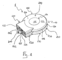
- a modular apparatus for allowing bi-directional data communication between a distribution network and a residential network is indicated with reference numeral 1. More generally, apparatus 1 allows data communication between a plurality of heterogeneous communication networks.
- Apparatus 1 is adapted to be located in a residential setting, but it is suitable to be located in business settings too.
- Apparatus 1 provides for a bridging (or routing, or gateway) function between an external network (such as a WAN) and one or more in-home networks (such as a LAN), thus allowing bi-directional data distribution between the external network and different kinds of residential or business appliances, such as computers, printers, faxes, photocopying machines, television sets, telephones, etc.
- an external network such as a WAN
- in-home networks such as a LAN
- apparatus 1 comprises a first device (or base module) 100 adapted to interface the distribution network (for example by ADSL or optical technology) and a second device (or first expansion module) 200 adapted to interface the residential network.
- the first and second devices are mechanically and electrically connected to each other and together form a stack 10.
- the first and second device communicate data reciprocally and with the distribution network and the residential network, respectively, using any of a variety of communication protocols.
- the first device 100 is preferably further adapted to be connected to the residential network so that, if a simple connection (e.g., a single link) is needed to transmit data to the appliances of the residential setting, the apparatus 1 can consist of a single module, i.e., only the first device 100.
- a simple connection e.g., a single link
- the second device can be further adapted to interface a second distribution network, either of the same type or, preferably, of a different type from the distribution network interfaced by the first device, so as to provide an additional or alternative link of the residential network (or networks) to external networks.
- the stack 10 may be placed horizontally or, preferably, vertically.
- the devices 100 and 200 within the stack may be placed in any order.
- the first device 100 is placed at the top of the stack and the second device 200 (and any other possible further expansion module, not shown) is placed below the first device 100, as shown in figure 1.
- a base element (not shown) is placed at the bottom of the stack 10 to support and hold the stack 10 over a table or the floor.
- the stack 10 may be hung on a wall: in particular, in case of vertical stack, the base element may comprise a vertical plate adapted to be hung on the wall and a horizontal plate adapted to support the stack, whereas in case of horizontal stack, the expansion module placed at the bottom of the stack may be provided with a plate for hanging the stack to the wall.
- the vertical stack of modules may be supported and rest directly on a table or other supporting surface without interposition of a base element.
- the modules 100 and 200 are flat in shape in order to be easily associated in a stack. They are preferably made of plastic material, for example of acrylonitrile butadiene styrene (ABS) filled with polycarbonate.
- ABS acrylonitrile butadiene styrene
- a modular apparatus 1 comprising just two devices, namely the base module 100 and the first expansion module 200
- the same considerations will fully apply to modular apparatuses comprising more than two devices, namely a base module and more that one expansion module.
- the external structural configuration of the various expansion modules is identical for the parts associated with connectivity with the other modules, said expansion modules being different from each other only with respect to the internal configuration and/or to the communication protocol used to interface different appliances or residential networks. Therefore, what said with respect to the expansion module 200 is fully applicable to any other expansion module intended to be used in the apparatus 1 of the invention.
- a second expansion module will be connected to the first expansion module 200 in the same way (and by means of the same elements) as the first expansion module 200 is connected to the base module 100.
- the base module 100 comprises a first portion' 110 which is circular-like in shape and a second portion 120 which is quadrangular-like in shape.
- the base module 100 further comprises an upper surface 130 (shown in figures 1 and 2), a bottom surface 140 (shown in fig. 3) and a side surface 150.
- the first portion 110 of the base module 100 comprises, at the upper surface 130, a central portion 111 which is slightly lifted up with respect to the surrounding portion 112 in order to create a circular opening 113 for allowing ventilation of the electronic and or optical devices provided into the base module 100.
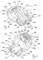
- the first portion 110 of the base module 100 further comprises, at the bottom surface 140, a plurality of vent slots (all indicated with 114 in figure 3) which contribute to the ventilation within the base module 100.
- a slot 115 for housing a card, e.g. a smart card, (not shown) for enabling data communication between the base module 100 and the distribution network is formed on the side surface 150 of the base module 100 (see figures 1 and 2).
- a connector 116 is provided on the bottom surface 140 of the base module 100, at an end of the first portion 110 thereof, for allowing electrical connection and data communication between the base module 100 and the first expansion module 200, as it will be better explained in the following.
- the second portion 120 comprises a frontal surface 121 (shown in figures 1 and 3) provided with a plurality of connectors and ports (all indicated with 122 in figure 1 and not visible in figures 2 and 3) for allowing electrical connections and data communication between the base module 100 and the distribution network and/or between the base module 100 and a first residential network or first residential appliances.
- a switch 123 is provided on the frontal surface 121 to allow functional activation of the base module 100.
- the bottom surface 140 further comprises a portion 141 for allowing mechanical connection between the base module 100 and the first expansion module 200.
- the portion 141 Around the portion 141, four projecting legs 142 are provided for placing the base module 100 on the first expansion module 200 when these module are stacked together.
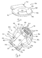
- Respective projecting bases 143 are provided for each leg 142, These projecting bases 143 are intended to be housed into corresponding recess seats 233 (see figure 4) provided on the first expansion module 200 for assisting correct alignment of the base module 100 over the first expansion module 200 when these modules are stacked together.
- Four holes 144 are further provided at the bottom surface 140 of the base module 100 for housing corresponding pins 234 (see figure 4) provided on the first expansion module 200, thus contributing to the alignment of these modules when stacked together.
- An undercut projecting seat 145 is provided at one end of portion 141 and an undercut pin 147 is provided at the opposite end of portion 141 for firmly securing the base module 100 to the first expansion module 200 as better explained in the following.
- the undercut projecting seat 145 is intended to be housed into a corresponding recess seat 235 (see figure 4) provided on the first expansion module 200.
- Two projecting surfaces 146 are provided on the opposite side to the portion 141 for contributing to the mechanical connection between the base module 100 and the first expansion module 200.
- the projecting surfaces 146 are intended to the housed into corresponding recess seats 236 (see figure 4) provided on the first expansion module 200.
- the portion 141 for allowing mechanical connection between the base module 100 and the first expansion module 200 is therefore defined by: the four projecting bases 143, the undercut projecting seat 145, the two projecting surfaces 146 and the undercut pin 147.
- a microswitch (not shown) is provided into the base module 100 for activating electrical supply (and, hence, data communication) between the base module 100 and the first expansion device 200 only when a stable and correct mechanical connection between these module is achieved.
- the microswitch is located at the bottom surface 140, preferably at the undercut projecting seat 145, and is switched on/off as better explained in the following.
- the first expansion module 200 comprises a first portion 210 which is circular-like in shape (having same dimension and shape of the first portion 110 of the base module 100) and a second portion 220 which is quadrangular-like in shape (having same dimension and shape of the second portion 120 of the base module 100).
- the first expansion module 200 further comprises an upper surface 230 (shown in figures 1 and 4), a bottom surface 240 (shown in fig. 5) and a side surface 250.
- the bottom surface 240 is structurally and functionally identical to the bottom surface 140 of the base module 100. Moreover, the bottom surface 240 preferably comprises a plurality of vent slots (all indicated with 214 in figure 5 and having the same locations of vent slots 114 on the bottom surface 140 of the base module 100) for allowing ventilation within the first expansion module 200.
- the bottom surface 240 further comprises a portion 241 intended for allowing mechanical connection between the first expansion module 200 and a second expansion module (not shown) in the same way as the base module 100 is mechanically connected to the first expansion module 200.
- a portion 241 intended for allowing mechanical connection between the first expansion module 200 and a second expansion module (not shown) in the same way as the base module 100 is mechanically connected to the first expansion module 200.
- the portion 241 Around the portion 241, four projecting legs 242, each provided on a respective projecting base 243, and four holes 244 are provided for assisting correct alignment of the first expansion module 200 over a possible additional expansion module, when these modules are stacked.
- An undercut projecting seat 245 is provided at one end of portion 241 and an undercut pin 247 is provided at the opposite end of the portion 241 for firmly securing the first expansion module 200 to an additional expansion module in the same way as the first expansion module 200 is firmly secured to the base module 100.
- Two projecting surfaces 246 are provided on the opposite side to the portion 241 for contributing to the mechanical connection between the first expansion module 200 and a possible additional module.
- the portion 241 for allowing mechanical connection between the first expansion module 200 and a possible additional module is therefore defined by: the four projecting bases 243, the undercut projecting seat 245, the two projecting surfaces 246 and the undercut pin 247.
- a connector 216 is further provided on the bottom surface 240 of the first expansion module 200, at one end of the first portion 210 thereof, for allowing electrical connection and data communication between the first expansion module 200 and a possible additional expansion module, in the same way as the base module 100 is electrically connected to the first expansion module 200.
- a microswitch (not shown) is provided into the first expansion module 200 for activating the electrical power supply from the first expansion module 200 to a possible additional module only when a stable and correct mechanical connection between these module is achieved.
- the microswitch is located at the bottom surface 240, preferably at the undercut projecting seat 245, and is switched on/off in the same way as the microswitch of the base module 100.
- the modules are adapted to being electrically supplied by an electrical supply device coupled to the base module, via a supply line implemented in the connectors that provide electrical coupling between the modules.
- an unregulated power supply device is coupled to the base module.
- the base module and each expansion module are provided with suitable stabilizing electronics to extract one or more stable supply voltages, as needed in each module, from the unregulated power supply.
- the microswitch of each specific expansion module is adapted to interrupt the supply line at the entrance of that module, so that until the microswitch remains open the power supply coming from the supply line in the input connector is not fed to the electronic equipment in the module itself nor to output connector, i.e. to the following expansion module or modules.
- the second portion 220 of the first expansion module 200 comprises a frontal surface 221 (shown in figures 1, 4 and 5) provided with a plurality of connectors and ports (all indicated with 222 in figure 1 and not shown in figures 4 and 5) for allowing electrical connections and data communication between the first expansion module 100 and a second residential network or second residential appliances, and/or between the first expansion module 100 and a distribution network.
- the upper surface 230 comprises a projecting plate 231 for allowing mechanical connection between the first expansion module 200 and the base module 100.
- This plate 231 is adapted to cooperate with portion 141 of the base module 100 for mechanically associating and firmly securing the first expansion module 200 to the base module 100, as it will be better explained in the following.
- the above mentioned recess seats 233, 235, 236 are respectively provided for housing the above mentioned projecting bases 143, undercut projecting seat 145 and projecting surfaces 146, when the modules are stacked.
- the above mentioned four pins 234 intended to be housed into the holes 144 of the base module 100 are provided on the upper surface 230.
- Plate 231 comprises a longitudinal undercut seat 232 housing an elongate element 300.
- Element 300 is held within the seat 232 by the undercut portion thereof and is only capable of sliding within seat 232 between a first operative position (shown in figures 1 and 4) and an opposite second operative position (not shown), wherein this element is pushed ahead.
- Element 300 acts as a locking element to firmly secure base module 100 and first expansion module 200 each to the other when they are stacked-and mechanically connected.
- a hole 301 is formed on the locking element 300.
- Hole 301 comprises a narrower end portion 302 adapted to tightly house undercut pin 147 when the base module 100 is stacked on the first expansion module 200 and the locking element 300 is at its second operative position.
- a connector 260 is provided on the upper surface 230 of the first expansion module 200, at the first portion 210 thereof, for allowing electrical connection and data communication between the first expansion module 200 and base module 100, as it will be better explained in the following.
- Connector 260 of the expansion module 200 is intended to mate and cooperate with connector 116 of the base module 100.
- the locking element 300 defines, in cooperation with the undercut projecting seat 150 and undercut pin 147 of the base module 100, an interconnecting device which, being operatively interposed between the base module 100 and the first expansion module 200, locks these modules each to the other, thus keeping a stable and correct mechanical and electrical connection between these modules over time.
- the mechanical connection between the base module 100 and the first expansion module 200 is effected by facing the bottom surface 140 of the base module 100 against the upper surface 230 of the first expansion module 200 and associating these module by housing, respectively, the pins 234 of the first expansion module 200 into the holes 144 of the base module, the projecting bases 143, undercut seat 145 and surfaces 146 of the base module 100 into the recess seats 233, 235, 236 of the first expansion module 200, and the undercut pin 147 of the base module 100 into the hole 301 of the locking element 300 (which is at its first operative position).
- connector 116 mates with connector 260. In this operative configuration the modules 100 and 200 are mechanically and electrically connected to each other, but they are still disconnectable and the electrical connection and data communication between these modules is still disabled.
- a free end 300a of the sliding element 300 is housed within the undercut projecting seat 145 of the base module 100 and the undercut pin 147 slides into the narrower end portion 302 of the hole 301 thus locking the first expansion module 200 to the base module 100 by firmly securing the pin 147 into the hole end portion 302 of the locking element 300 and the end portion 300a of the locking element 300 into the projecting undercut seat 145 of the base module 100.
- the modules 100 and 200 are locked to each other.
- the electrical connection and data communication between the base module 100 and the expansion module 200 occurs through connectors 116 and 260, which are mated when the modules are stacked.
- the electrical supply (and, hence, data communication) is activated only when the microswitch provided on the base module 100 is switched on by the end portion 300a of locking element 300, i.e. when locking element 300 is pushed ahead to its second operative position.
- the microswitch is switch off and the electrical supply between the base module 100 and the first expansion module 200 is deactivated.
- Communication between the base module 100 and the expansion module 200 can be achieved by providing a processor (such as a microprocessor or microcontroller) (not shown) into the base modules of the apparatus 1.
- a processor such as a microprocessor or microcontroller
- the processor housed into the base module 100 can be a network processor which routes different data to different expansion module according to predetermined communication protocols via one or more appropriate communication buses.
- a serial connection line such as ISO 7816-3, further connects a microprocessor in the base module 100 with microcontrollers of each expansion modules in a repeated master-slave chain configuration, that is a serial configuration wherein each module acts as a master for the following module and as a slave for the previous one.
- a serial connection line such as ISO 7816-3
- the serial communication line also includes address lines through which the microprocessor in the base module can address the microcontrollers in the expansion modules.
- the single bi-directional serial communication line may be replaced by a serial communication signal line bus, such as an I2C bus, wherein the base module acts as a master and each expansion module acts as a slave, and a respective address is assigned to each expansion module; some, e.g. two, of the lines of the serial communication bus are for example used to assign the respective address to the expansion modules; an expansion module reads the address assigned thereto and generates, for example on an incremental basis, a new address to be assigned to the next expansion module which will be added.
- a serial communication signal line bus such as an I2C bus
- a contactless data transmitting/receiving device is used in place of the serial connection line.
- the base module comprises a chip acting as controller/reader/writer (such as a CRX14 contactless coupler chip from STMicroelectronics) whereas the expansion modules comprises respective chips acting as memories (such as a SRIX4K contactless memory chip from STMicroelectronics).
- the processor of the base module communicates simultaneously, via the controller/reader/writer chip with memories of the expansion modules by a wireless system for identification thereof.
- the memory chips are powered from the reader chip by radiofrequency when the expansion modules are within a distance range of 10-20 cm from the base module. Therefore, the test for identification here can occur even when the expansion modules are not powered (i.e. even when the electrical supply between the modules is not activated).
Landscapes
- Engineering & Computer Science (AREA)
- Computer Networks & Wireless Communication (AREA)
- Signal Processing (AREA)
- Connector Housings Or Holding Contact Members (AREA)
Claims (12)
- Modulare Vorrichtung (1) zur Datenkommunikation zwischen einem Verteilernetzwerk und einem privaten Netzwerk (residential network), welche umfasst:- eine erste Vorrichtung (100), die einen ersten Verbinder (116) aufweist, welcher fest mit der Vorrichtung verbunden und zur Kopplung mit einem Verteilernetzwerk ausgeführt ist,- mindestens eine zweite Vorrichtung (200), die mindestens einen zweiten Verbinder (260) aufweist, welcher fest mit der Vorrichtung verbunden und zur Kopplung mit einem privaten Netzwerk ausgeführt ist und mechanisch und elektrisch mit der ersten Vorrichtung verbunden werden kann,- mindestens eine Kopplungseinrichtung, die so ausgeführt, ist, dass sie die erste Vorrichtung (100) und mindestens eine zweite Vorrichtung (200) miteinander verriegelt und die elektrische Versorgung zwischen der ersten Vorrichtung (100) und der mindestens einen zweiten Vorrichtung (200) aktiviert, wobei die mindestens eine Kopplungseinrichtung eine erste Arbeitskonfiguration, in der die erste (100) und die mindestens eine zweite Vorrichtung (200) entriegelt werden, sodass die Verbindung zwischen ihnen gelöst werden kann und die elektrische Versorgung zwischen den Modulen unterbrochen wird, und eine zweite Arbeitskonfiguration vorgibt, in der die erste (100) und die mindestens eine zweite Vorrichtung (200) verriegelt werden, sodass sie nicht voneinander gelöst werden können und die elektrische Versorgung zwischen den Modulen aktiviert wird,dadurch gekennzeichnet, dass mindestens eine Kopplungseinrichtung ein Verriegelungselement (300) aufweist, welches zwischen einer ersten Arbeitsposition, die der ersten Arbeitskonfiguration der Vorrichtung (1) entspricht, und einer zweiten Arbeitsposition, die der zweiten Arbeitskonfiguration der Vorrichtung (1) entspricht, gleitbar ist.
- Modulare Vorrichtung (1) nach Anspruch 1, welche ferner umfasst:- einen ersten Sitz (145) für das auf der ersten Vorrichtung ausgebildete Verriegelungselement,- einen zweiten Sitz (232) für das auf der mindestens einen zweiten Vorrichtung ausgebildete Verriegelungselement,wobei der zweite Sitz (232) das Verriegelungselement (300) gleitbar aufnimmt und der erste Sitz (145) so ausgeführt ist, dass er ein freies Ende des Verriegelungselements (300) aufnimmt, wenn sich das Verriegelungselement (300) in der zweiten Arbeitsposition befindet.
- Modulare Vorrichtung (1) nach Anspruch 2, welche ferner umfasst:- einen Stift (247), der mit der ersten Vorrichtung einstückig ausgebildet ist, und- ein Loch (301), das im Verriegelungselement ausgebildet ist,wobei das Loch (301) den Stift gleitbar aufnimmt und einen schmaleren Endabschnitt aufweist, der für ein Zusammenwirken mit dem Stift (247) ausgeführt ist, wenn sich das Verriegelungselement (300) in der zweiten Arbeitsposition befindet, sodass die erste Vorrichtung (100) sicher am Verriegelungselement (300) befestigt wird.
- Modulare Vorrichtung (1) nach einem der vorhergehenden Ansprüche, die ferner einen Schalter aufweist, der so ausgeführt ist, dass er vom Verriegelungselement (300) eingeschaltet wird, wenn sich das Verriegelungselement (300) in der zweiten Arbeitsposition befindet, wodurch die elektrische Versorgung zwischen der ersten und der mindestens einen zweiten Vorrichtung aktiviert wird, und vom Verriegelungselement ausgeschaltet wird, wenn das Verriegelungselement aus der zweiten Arbeitsposition herausbewegt wird, wodurch die elektrische Versorgung zwischen der ersten (100) und der mindestens einen zweiten (200) Vorrichtung deaktiviert wird.
- Modulare Vorrichtung (1) nach einem der vorhergehenden Ansprüche, die ferner einen ersten Prozessor, der in der ersten Vorrichtung aufgenommen ist, einen zweiten Prozessor, der in der in der mindestens einen zweiten Vorrichtung aufgenommen ist, und eine Datenübertragungs/-empfangsleitung zwischen dem ersten und zweiten Prozessor umfasst.
- Modulare Vorrichtung (1) nach Anspruch 5, bei der der erste Prozessor ein Mikroprozessor, der zweite Prozessor eine Mikrosteuereinheit und die Datenübertragungs/-empfangsleitung eine serielle Verbindungsleitung ist.
- Modulare Vorrichtung (1) nach einem der Ansprüche 1 bis 4, welche ferner einen ersten Prozessor, der in der ersten Vorrichtung (100) aufgenommen ist, und eine kontaktlose Datenübertragungs/-empfangsleitung zwischen dem ersten Mikroprozessor und der mindestens einen zweiten Vorrichtung (200) umfasst.
- Modulare Vorrichtung (1) nach Anspruch 7, bei der der erste Prozessor ein Netzwerkprozessor ist und die kontaktlose Datenübertragungs/-empfangsleitung einen Lesechip enthält, der in der ersten Vorrichtung aufgenommen ist und einen Speicherchip enthält, der in der mindestens einen zweiten Vorrichtung aufgenommen ist.
- Verfahren zur Datenkommunikation zwischen einem Verteilernetzwerk und einem privaten Netzwerk, welches die folgenden Schritte umfasst:- Koppeln eines Verteilernetzwerks an eine erste Vorrichtung (100), welche einen ersten Verbinder (116) aufweist, der fest mit der Vorrichtung verbunden ist,- Koppeln eines privaten Netzwerks an mindestens eine zweite Vorrichtung (200), die mindestens einen zweiten Verbinder (260) aufweist, welcher fest mit der Vorrichtung verbunden ist,- elektrisch und mechanisches Verbinden der ersten Vorrichtung (100) mit der mindestens einen zweiten Vorrichtung (200),- Verriegeln der ersten Vorrichtung (100) und der mindestens einen zweiten Vorrichtung (200) miteinander und Aktivieren der elektrischen Versorgung zwischen der ersten Vorrichtung (100) und der mindestens einen zweiten Vorrichtung (200) mit Hilfe mindestens einer Kopplungseinrichtung,dadurch gekennzeichnet, dass der Schritt der Verriegelung der ersten Vorrichtung (100) und der mindestens einen zweiten Vorrichtung (200) miteinander und der Aktivierung der elektrischen Versorgung zwischen der ersten Vorrichtung und der mindestens einen zweiten Vorrichtung die folgenden Schritte umfasst:- gleitendes Bewegen mindestens eines Verriegelungselements (300) von einer ersten Arbeitsposition, bei der die erste (100) und die mindestens eine zweite Vorrichtung (200) entriegelt und voneinander gelöst werden und die elektrische Versorgung zwischen der ersten (100) und der mindestens einen zweiten Vorrichtung (200) unterbrochen wird, zu einer zweiten Arbeitsposition, in der die erste (100) und die mindestens eine zweite Vorrichtung (200) verriegelt werden, sodass sie nicht voneinander gelöst werden können und die elektrische Versorgung zwischen der ersten und der mindestens einen zweiten Vorrichtung aktiviert wird.
- Verfahren nach Anspruch 9, bei dem der Schritt der gleitenden Bewegung des Verriegelungselements (300) von der ersten Arbeitsposition in die zweite Arbeitsposition den Schritt des Einschaltens eines Schalters umfasst, wenn sich das Verriegelungselement (300) in der zweiten Arbeitsposition befindet, wodurch wiederum die elektrische Versorgung zwischen der ersten (100) und der mindestens einen zweiten Vorrichtung (200) aktiviert wird.
- Verfahren nach Anspruch 10, bei dem der Schritt des Einschaltens des Schalters ferner die folgenden Schritte umfasst:- Aktivieren der elektrischen Versorgung zwischen der ersten (100) und der mindestens einen zweiten (200) Vorrichtung,- Testen der mindestens einen zweiten Vorrichtung (200) zur Erkennung derselben mit Hilfe der ersten Vorrichtung (100) und,- wenn der Test positiv ausfällt, Freigeben der Datenkommunikation zwischen der ersten (100) und der mindestens einen zweiten Vorrichtung (200) und,- wenn der Test negativ ausfällt, Sperren der Datenkommunikation zwischen der ersten (100) und der mindestens einen zweiten Vorrichtung (200).
- Lokales Kommunikationsnetzwerk, welches eine Kopplung privater Geräte ermöglicht, die eine modulare Vorrichtung (1) gemäß einem der Ansprüche 1 bis 8 umfassen.
Priority Applications (1)
| Application Number | Priority Date | Filing Date | Title |
|---|---|---|---|
| AT02793064T ATE334490T1 (de) | 2002-12-18 | 2002-12-18 | Modulare vorrichtung und verfahren zu der datenübertragung zwischen einem datenverteilungsnetzwerk und einem heimischen telekommunikationsnetzwerk |
Applications Claiming Priority (1)
| Application Number | Priority Date | Filing Date | Title |
|---|---|---|---|
| PCT/EP2002/014482 WO2004055949A1 (en) | 2002-12-18 | 2002-12-18 | Modular apparatus and method for data communication between a distribution network and a residential network |
Publications (2)
| Publication Number | Publication Date |
|---|---|
| EP1573863A1 EP1573863A1 (de) | 2005-09-14 |
| EP1573863B1 true EP1573863B1 (de) | 2006-07-26 |
Family
ID=32523980
Family Applications (1)
| Application Number | Title | Priority Date | Filing Date |
|---|---|---|---|
| EP02793064A Expired - Lifetime EP1573863B1 (de) | 2002-12-18 | 2002-12-18 | Modulare vorrichtung und verfahren zu der datenübertragung zwischen einem datenverteilungsnetzwerk und einem heimischen telekommunikationsnetzwerk |
Country Status (5)
| Country | Link |
|---|---|
| US (1) | US7588472B2 (de) |
| EP (1) | EP1573863B1 (de) |
| AU (1) | AU2002358752A1 (de) |
| DE (1) | DE60213487T2 (de) |
| WO (1) | WO2004055949A1 (de) |
Families Citing this family (25)
| Publication number | Priority date | Publication date | Assignee | Title |
|---|---|---|---|---|
| US7676584B2 (en) * | 2005-05-17 | 2010-03-09 | Kid Group Llc | Method and apparatus for providing games and content |
| US8032705B2 (en) * | 2005-05-17 | 2011-10-04 | Kid Group Llc | Method and apparatus for providing games and content |
| KR100772412B1 (ko) * | 2006-07-18 | 2007-11-01 | 삼성전자주식회사 | 홈 컨트롤 네트워크 제어 장치 및 방법 |
| EP2226902A3 (de) * | 2009-03-06 | 2013-03-13 | Phitek Systems Limited | Bordunterhaltungssystemverbinder |
| WO2011146429A1 (en) | 2010-05-17 | 2011-11-24 | Thales Avionics, Inc. | Airline passenger seat modular user interface device |
| US9191203B2 (en) | 2013-08-06 | 2015-11-17 | Bedrock Automation Platforms Inc. | Secure industrial control system |
| US8862802B2 (en) | 2011-12-30 | 2014-10-14 | Bedrock Automation Platforms Inc. | Switch fabric having a serial communications interface and a parallel communications interface |
| US10834820B2 (en) | 2013-08-06 | 2020-11-10 | Bedrock Automation Platforms Inc. | Industrial control system cable |
| US11967839B2 (en) | 2011-12-30 | 2024-04-23 | Analog Devices, Inc. | Electromagnetic connector for an industrial control system |
| US9600434B1 (en) | 2011-12-30 | 2017-03-21 | Bedrock Automation Platforms, Inc. | Switch fabric having a serial communications interface and a parallel communications interface |
| US11144630B2 (en) | 2011-12-30 | 2021-10-12 | Bedrock Automation Platforms Inc. | Image capture devices for a secure industrial control system |
| US12061685B2 (en) | 2011-12-30 | 2024-08-13 | Analog Devices, Inc. | Image capture devices for a secure industrial control system |
| US9467297B2 (en) | 2013-08-06 | 2016-10-11 | Bedrock Automation Platforms Inc. | Industrial control system redundant communications/control modules authentication |
| US9437967B2 (en) | 2011-12-30 | 2016-09-06 | Bedrock Automation Platforms, Inc. | Electromagnetic connector for an industrial control system |
| US8971072B2 (en) | 2011-12-30 | 2015-03-03 | Bedrock Automation Platforms Inc. | Electromagnetic connector for an industrial control system |
| US11314854B2 (en) | 2011-12-30 | 2022-04-26 | Bedrock Automation Platforms Inc. | Image capture devices for a secure industrial control system |
| US9727511B2 (en) | 2011-12-30 | 2017-08-08 | Bedrock Automation Platforms Inc. | Input/output module with multi-channel switching capability |
| US9449756B2 (en) | 2013-05-02 | 2016-09-20 | Bedrock Automation Platforms Inc. | Electromagnetic connectors |
| US10834094B2 (en) | 2013-08-06 | 2020-11-10 | Bedrock Automation Platforms Inc. | Operator action authentication in an industrial control system |
| US8868813B2 (en) | 2011-12-30 | 2014-10-21 | Bedrock Automation Platforms Inc. | Communications control system with a serial communications interface and a parallel communications interface |
| US10613567B2 (en) | 2013-08-06 | 2020-04-07 | Bedrock Automation Platforms Inc. | Secure power supply for an industrial control system |
| US9300083B2 (en) | 2013-09-30 | 2016-03-29 | Apple Inc. | Stackable magnetically-retained connector interface |
| CN111293495B (zh) | 2014-07-07 | 2022-05-24 | 基岩自动化平台公司 | 工业控制系统电缆 |
| CN105867526A (zh) * | 2015-01-22 | 2016-08-17 | 鸿富锦精密工业(深圳)有限公司 | 电子装置 |
| US12621331B2 (en) * | 2020-11-13 | 2026-05-05 | Cyberark Software Ltd. | Detection of security risks based on secretless connection data |
Family Cites Families (7)
| Publication number | Priority date | Publication date | Assignee | Title |
|---|---|---|---|---|
| US4718858A (en) * | 1986-06-16 | 1988-01-12 | Western Digital Corporation | Mechanical interconnect system for electronic units enclosed in stackable housings |
| US5311397A (en) * | 1992-08-06 | 1994-05-10 | Logistics Management Inc. | Computer with modules readily replaceable by unskilled personnel |
| US5959992A (en) * | 1995-12-20 | 1999-09-28 | International Business Machines Corporation | Process for operating a communication equipment comprising a set of mechanically connected apparatuses being vertically and horizontally packed, and apparatus using the same |
| US6537109B1 (en) * | 1997-01-16 | 2003-03-25 | Hewlett-Packard Company | Chainable I/O termination block system |
| WO2000013054A1 (en) * | 1998-09-02 | 2000-03-09 | The Whitaker Corporation | Transceiver housing and ejection mechanism therefore |
| EP1317783B1 (de) * | 2000-09-12 | 2006-10-18 | Tyco Electronics AMP GmbH | Modulares verbindungssystem für ethernet-anwendungen im industriellen sektor |
| US20020065935A1 (en) * | 2000-10-18 | 2002-05-30 | Koperda Frank R. | Method and system for a modular residential gateway |
-
2002
- 2002-12-18 EP EP02793064A patent/EP1573863B1/de not_active Expired - Lifetime
- 2002-12-18 WO PCT/EP2002/014482 patent/WO2004055949A1/en not_active Ceased
- 2002-12-18 AU AU2002358752A patent/AU2002358752A1/en not_active Abandoned
- 2002-12-18 US US10/538,875 patent/US7588472B2/en not_active Expired - Lifetime
- 2002-12-18 DE DE60213487T patent/DE60213487T2/de not_active Expired - Lifetime
Also Published As
| Publication number | Publication date |
|---|---|
| US7588472B2 (en) | 2009-09-15 |
| DE60213487T2 (de) | 2007-08-23 |
| DE60213487D1 (de) | 2006-09-07 |
| AU2002358752A8 (en) | 2004-07-09 |
| US20080123669A1 (en) | 2008-05-29 |
| EP1573863A1 (de) | 2005-09-14 |
| AU2002358752A1 (en) | 2004-07-09 |
| WO2004055949A1 (en) | 2004-07-01 |
Similar Documents
| Publication | Publication Date | Title |
|---|---|---|
| US7588472B2 (en) | Modular apparatus and method for data communication between a distribution network and a residential network | |
| CN101682800B (zh) | 使用共模传输识别通信接插系统中的接插线连接的系统和方法 | |
| US6726509B2 (en) | Stackable power supply system | |
| US6944689B2 (en) | Printer/powered peripheral node system | |
| US6059583A (en) | Interconnection between media connectors of unknown interface standards and a computer communications card | |
| EP2345106B1 (de) | Abschlusskappe zur verwendung in einem verdrahteten netzwerkverwaltungssystem | |
| US20040161964A1 (en) | RJ-45 jack with RJ-11 detection | |
| US20080178014A1 (en) | Power Sourcing Unit for Power Over Ethernet System | |
| JP2001274567A (ja) | 取り外し可能な構成要素のための電気的コネクタ | |
| US20060187954A1 (en) | Expandable modular residential gateway | |
| CA2147948A1 (en) | Connector module for local area network | |
| CN103548217A (zh) | 用于数据网络的接线板组件适配器 | |
| US7513801B2 (en) | Apparatus with detachably connected memory-card type adapter | |
| US5404268A (en) | Interface allowing normal or inverted insertion of data communications card | |
| US6905351B1 (en) | Electrical connector for open/close type | |
| BR102017021868A2 (pt) | Sistema de identificação dos pares de portas e dos respectivos cabos de conexão em paineis de ligação de redes de telecomunicação | |
| US6671764B2 (en) | PC adapter card with an interchangeable connector set | |
| US20020057206A1 (en) | Method and appparatus for an improved remotely switchable power supply | |
| US6125034A (en) | Computer having internally mounted peripheral devices with moveable adapter | |
| WO2009134222A1 (en) | System and method for efficient association of a power outlet and device | |
| US5810613A (en) | Circuit board connecting device | |
| AU2003259777B2 (en) | Improved connector assembly that maintains backward compatibility | |
| CN1965555B (zh) | 用于插入插入式模块的插入式模块框以及插入式模块 | |
| AU673386B2 (en) | LAN interface | |
| US7025611B2 (en) | Connection device |
Legal Events
| Date | Code | Title | Description |
|---|---|---|---|
| PUAI | Public reference made under article 153(3) epc to a published international application that has entered the european phase |
Free format text: ORIGINAL CODE: 0009012 |
|
| 17P | Request for examination filed |
Effective date: 20050607 |
|
| AK | Designated contracting states |
Kind code of ref document: A1 Designated state(s): AT BE BG CH CY CZ DE DK EE ES FI FR GB GR IE IT LI LU MC NL PT SE SI SK TR |
|
| AX | Request for extension of the european patent |
Extension state: AL LT LV MK RO |
|
| RAP1 | Party data changed (applicant data changed or rights of an application transferred) |
Owner name: TELECOM ITALIA S.P.A. Owner name: PIRELLI & C. S.P.A. |
|
| GRAP | Despatch of communication of intention to grant a patent |
Free format text: ORIGINAL CODE: EPIDOSNIGR1 |
|
| GRAC | Information related to communication of intention to grant a patent modified |
Free format text: ORIGINAL CODE: EPIDOSCIGR1 |
|
| DAX | Request for extension of the european patent (deleted) | ||
| RIN1 | Information on inventor provided before grant (corrected) |
Inventor name: SIMONELLI, FRANCESCO, Inventor name: TAGLIABUE, GIOVANNI, Inventor name: OLIVETI, GUIDO,C/O PIRELLI CAVI E SISTEMI S.P.A. |
|
| RIN1 | Information on inventor provided before grant (corrected) |
Inventor name: TAGLIABUE, GIOVANNI, Inventor name: SIMONELLI, FRANCESCO, Inventor name: OLIVETI, GUIDO,C/O PIRELLI CAVI E SISTEMI S.P.A. |
|
| GRAS | Grant fee paid |
Free format text: ORIGINAL CODE: EPIDOSNIGR3 |
|
| GRAA | (expected) grant |
Free format text: ORIGINAL CODE: 0009210 |
|
| AK | Designated contracting states |
Kind code of ref document: B1 Designated state(s): AT BE BG CH CY CZ DE DK EE ES FI FR GB GR IE IT LI LU MC NL PT SE SI SK TR |
|
| PG25 | Lapsed in a contracting state [announced via postgrant information from national office to epo] |
Ref country code: SK Free format text: LAPSE BECAUSE OF FAILURE TO SUBMIT A TRANSLATION OF THE DESCRIPTION OR TO PAY THE FEE WITHIN THE PRESCRIBED TIME-LIMIT Effective date: 20060726 Ref country code: SI Free format text: LAPSE BECAUSE OF FAILURE TO SUBMIT A TRANSLATION OF THE DESCRIPTION OR TO PAY THE FEE WITHIN THE PRESCRIBED TIME-LIMIT Effective date: 20060726 Ref country code: NL Free format text: LAPSE BECAUSE OF FAILURE TO SUBMIT A TRANSLATION OF THE DESCRIPTION OR TO PAY THE FEE WITHIN THE PRESCRIBED TIME-LIMIT Effective date: 20060726 Ref country code: LI Free format text: LAPSE BECAUSE OF FAILURE TO SUBMIT A TRANSLATION OF THE DESCRIPTION OR TO PAY THE FEE WITHIN THE PRESCRIBED TIME-LIMIT Effective date: 20060726 Ref country code: FI Free format text: LAPSE BECAUSE OF FAILURE TO SUBMIT A TRANSLATION OF THE DESCRIPTION OR TO PAY THE FEE WITHIN THE PRESCRIBED TIME-LIMIT Effective date: 20060726 Ref country code: CZ Free format text: LAPSE BECAUSE OF FAILURE TO SUBMIT A TRANSLATION OF THE DESCRIPTION OR TO PAY THE FEE WITHIN THE PRESCRIBED TIME-LIMIT Effective date: 20060726 Ref country code: BE Free format text: LAPSE BECAUSE OF FAILURE TO SUBMIT A TRANSLATION OF THE DESCRIPTION OR TO PAY THE FEE WITHIN THE PRESCRIBED TIME-LIMIT Effective date: 20060726 Ref country code: CH Free format text: LAPSE BECAUSE OF FAILURE TO SUBMIT A TRANSLATION OF THE DESCRIPTION OR TO PAY THE FEE WITHIN THE PRESCRIBED TIME-LIMIT Effective date: 20060726 Ref country code: AT Free format text: LAPSE BECAUSE OF FAILURE TO SUBMIT A TRANSLATION OF THE DESCRIPTION OR TO PAY THE FEE WITHIN THE PRESCRIBED TIME-LIMIT Effective date: 20060726 |
|
| REG | Reference to a national code |
Ref country code: GB Ref legal event code: FG4D |
|
| REG | Reference to a national code |
Ref country code: CH Ref legal event code: EP |
|
| REG | Reference to a national code |
Ref country code: IE Ref legal event code: FG4D |
|
| REF | Corresponds to: |
Ref document number: 60213487 Country of ref document: DE Date of ref document: 20060907 Kind code of ref document: P |
|
| PG25 | Lapsed in a contracting state [announced via postgrant information from national office to epo] |
Ref country code: DK Free format text: LAPSE BECAUSE OF FAILURE TO SUBMIT A TRANSLATION OF THE DESCRIPTION OR TO PAY THE FEE WITHIN THE PRESCRIBED TIME-LIMIT Effective date: 20061026 Ref country code: BG Free format text: LAPSE BECAUSE OF FAILURE TO SUBMIT A TRANSLATION OF THE DESCRIPTION OR TO PAY THE FEE WITHIN THE PRESCRIBED TIME-LIMIT Effective date: 20061026 Ref country code: SE Free format text: LAPSE BECAUSE OF FAILURE TO SUBMIT A TRANSLATION OF THE DESCRIPTION OR TO PAY THE FEE WITHIN THE PRESCRIBED TIME-LIMIT Effective date: 20061026 |
|
| PG25 | Lapsed in a contracting state [announced via postgrant information from national office to epo] |
Ref country code: ES Free format text: LAPSE BECAUSE OF FAILURE TO SUBMIT A TRANSLATION OF THE DESCRIPTION OR TO PAY THE FEE WITHIN THE PRESCRIBED TIME-LIMIT Effective date: 20061106 |
|
| PG25 | Lapsed in a contracting state [announced via postgrant information from national office to epo] |
Ref country code: IE Free format text: LAPSE BECAUSE OF NON-PAYMENT OF DUE FEES Effective date: 20061218 |
|
| PG25 | Lapsed in a contracting state [announced via postgrant information from national office to epo] |
Ref country code: PT Free format text: LAPSE BECAUSE OF FAILURE TO SUBMIT A TRANSLATION OF THE DESCRIPTION OR TO PAY THE FEE WITHIN THE PRESCRIBED TIME-LIMIT Effective date: 20061226 |
|
| PG25 | Lapsed in a contracting state [announced via postgrant information from national office to epo] |
Ref country code: MC Free format text: LAPSE BECAUSE OF NON-PAYMENT OF DUE FEES Effective date: 20061231 |
|
| NLV1 | Nl: lapsed or annulled due to failure to fulfill the requirements of art. 29p and 29m of the patents act | ||
| ET | Fr: translation filed | ||
| PLBE | No opposition filed within time limit |
Free format text: ORIGINAL CODE: 0009261 |
|
| STAA | Information on the status of an ep patent application or granted ep patent |
Free format text: STATUS: NO OPPOSITION FILED WITHIN TIME LIMIT |
|
| 26N | No opposition filed |
Effective date: 20070427 |
|
| PG25 | Lapsed in a contracting state [announced via postgrant information from national office to epo] |
Ref country code: GR Free format text: LAPSE BECAUSE OF FAILURE TO SUBMIT A TRANSLATION OF THE DESCRIPTION OR TO PAY THE FEE WITHIN THE PRESCRIBED TIME-LIMIT Effective date: 20061027 |
|
| PG25 | Lapsed in a contracting state [announced via postgrant information from national office to epo] |
Ref country code: EE Free format text: LAPSE BECAUSE OF FAILURE TO SUBMIT A TRANSLATION OF THE DESCRIPTION OR TO PAY THE FEE WITHIN THE PRESCRIBED TIME-LIMIT Effective date: 20060726 |
|
| PG25 | Lapsed in a contracting state [announced via postgrant information from national office to epo] |
Ref country code: LU Free format text: LAPSE BECAUSE OF NON-PAYMENT OF DUE FEES Effective date: 20061218 Ref country code: TR Free format text: LAPSE BECAUSE OF FAILURE TO SUBMIT A TRANSLATION OF THE DESCRIPTION OR TO PAY THE FEE WITHIN THE PRESCRIBED TIME-LIMIT Effective date: 20060726 |
|
| PG25 | Lapsed in a contracting state [announced via postgrant information from national office to epo] |
Ref country code: CY Free format text: LAPSE BECAUSE OF FAILURE TO SUBMIT A TRANSLATION OF THE DESCRIPTION OR TO PAY THE FEE WITHIN THE PRESCRIBED TIME-LIMIT Effective date: 20060726 |
|
| REG | Reference to a national code |
Ref country code: DE Ref legal event code: R082 Ref document number: 60213487 Country of ref document: DE Representative=s name: HOFFMANN - EITLE, DE |
|
| REG | Reference to a national code |
Ref country code: FR Ref legal event code: TP Owner name: ADB BROADBAND S.P.A., IT Effective date: 20120109 Ref country code: FR Ref legal event code: CD Owner name: ADB BROADBAND S.P.A., IT Effective date: 20120109 |
|
| REG | Reference to a national code |
Ref country code: DE Ref legal event code: R082 Ref document number: 60213487 Country of ref document: DE Representative=s name: HOFFMANN - EITLE, DE Effective date: 20120208 Ref country code: DE Ref legal event code: R081 Ref document number: 60213487 Country of ref document: DE Owner name: ADB BROADBAND S.P.A., IT Free format text: FORMER OWNER: PIRELLI & C. S.P.A., TELECOM ITALIA S.P.A., , IT Effective date: 20120208 Ref country code: DE Ref legal event code: R082 Ref document number: 60213487 Country of ref document: DE Representative=s name: HOFFMANN - EITLE PATENT- UND RECHTSANWAELTE PA, DE Effective date: 20120208 Ref country code: DE Ref legal event code: R081 Ref document number: 60213487 Country of ref document: DE Owner name: ADB BROADBAND S.P.A., IT Free format text: FORMER OWNERS: PIRELLI & C. S.P.A., MAILAND/MILANO, IT; TELECOM ITALIA S.P.A., MILAN, IT Effective date: 20120208 |
|
| PGFP | Annual fee paid to national office [announced via postgrant information from national office to epo] |
Ref country code: FR Payment date: 20121126 Year of fee payment: 11 |
|
| PGFP | Annual fee paid to national office [announced via postgrant information from national office to epo] |
Ref country code: GB Payment date: 20121212 Year of fee payment: 11 |
|
| PGFP | Annual fee paid to national office [announced via postgrant information from national office to epo] |
Ref country code: DE Payment date: 20121219 Year of fee payment: 11 |
|
| REG | Reference to a national code |
Ref country code: DE Ref legal event code: R119 Ref document number: 60213487 Country of ref document: DE |
|
| GBPC | Gb: european patent ceased through non-payment of renewal fee |
Effective date: 20131218 |
|
| REG | Reference to a national code |
Ref country code: DE Ref legal event code: R119 Ref document number: 60213487 Country of ref document: DE Effective date: 20140701 |
|
| REG | Reference to a national code |
Ref country code: FR Ref legal event code: ST Effective date: 20140829 |
|
| PG25 | Lapsed in a contracting state [announced via postgrant information from national office to epo] |
Ref country code: DE Free format text: LAPSE BECAUSE OF NON-PAYMENT OF DUE FEES Effective date: 20140701 |
|
| PG25 | Lapsed in a contracting state [announced via postgrant information from national office to epo] |
Ref country code: GB Free format text: LAPSE BECAUSE OF NON-PAYMENT OF DUE FEES Effective date: 20131218 Ref country code: FR Free format text: LAPSE BECAUSE OF NON-PAYMENT OF DUE FEES Effective date: 20131231 |
|
| REG | Reference to a national code |
Ref country code: GB Ref legal event code: 732E Free format text: REGISTERED BETWEEN 20150319 AND 20150325 |
|
| REG | Reference to a national code |
Ref country code: GB Ref legal event code: 732E Free format text: REGISTERED BETWEEN 20150514 AND 20150520 |
|
| REG | Reference to a national code |
Ref country code: FR Ref legal event code: TP Owner name: ADVANCED DIGITAL BROADCAST S.A., CH Effective date: 20150511 |
|
| PG25 | Lapsed in a contracting state [announced via postgrant information from national office to epo] |
Ref country code: IT Free format text: LAPSE BECAUSE OF NON-PAYMENT OF DUE FEES Effective date: 20151218 |
|
| PG25 | Lapsed in a contracting state [announced via postgrant information from national office to epo] |
Ref country code: IT Free format text: LAPSE BECAUSE OF NON-PAYMENT OF DUE FEES Effective date: 20151218 |
|
| PGRI | Patent reinstated in contracting state [announced from national office to epo] |
Ref country code: IT Effective date: 20170710 |
|
| PGFP | Annual fee paid to national office [announced via postgrant information from national office to epo] |
Ref country code: IT Payment date: 20201221 Year of fee payment: 19 |
|
| PG25 | Lapsed in a contracting state [announced via postgrant information from national office to epo] |
Ref country code: IT Free format text: LAPSE BECAUSE OF NON-PAYMENT OF DUE FEES Effective date: 20211231 |