EP1573933B1 - Verfahren und system zum empfangen eines Ultrabreitbandsignals mit selbstanpassender Anzahl von Ausbreitungswegen - Google Patents
Verfahren und system zum empfangen eines Ultrabreitbandsignals mit selbstanpassender Anzahl von Ausbreitungswegen Download PDFInfo
- Publication number
- EP1573933B1 EP1573933B1 EP03815405A EP03815405A EP1573933B1 EP 1573933 B1 EP1573933 B1 EP 1573933B1 EP 03815405 A EP03815405 A EP 03815405A EP 03815405 A EP03815405 A EP 03815405A EP 1573933 B1 EP1573933 B1 EP 1573933B1
- Authority
- EP
- European Patent Office
- Prior art keywords
- correlation
- direct
- pulses
- elementary
- pulse
- Prior art date
- Legal status (The legal status is an assumption and is not a legal conclusion. Google has not performed a legal analysis and makes no representation as to the accuracy of the status listed.)
- Expired - Lifetime
Links
Images


Classifications
-
- H—ELECTRICITY
- H04—ELECTRIC COMMUNICATION TECHNIQUE
- H04B—TRANSMISSION
- H04B1/00—Details of transmission systems, not covered by a single one of groups H04B3/00 - H04B13/00; Details of transmission systems not characterised by the medium used for transmission
- H04B1/69—Spread spectrum techniques
- H04B1/7163—Spread spectrum techniques using impulse radio
- H04B1/719—Interference-related aspects
-
- H—ELECTRICITY
- H04—ELECTRIC COMMUNICATION TECHNIQUE
- H04B—TRANSMISSION
- H04B1/00—Details of transmission systems, not covered by a single one of groups H04B3/00 - H04B13/00; Details of transmission systems not characterised by the medium used for transmission
- H04B1/69—Spread spectrum techniques
- H04B1/7163—Spread spectrum techniques using impulse radio
- H04B1/71637—Receiver aspects
Definitions
- the invention relates to a method and a system for receiving an ultra-broadband signal with a number of self-adaptive propagation paths.
- the technique of radio communications in ultra-wide band signal does not use a carrier frequency. Instead of modulating a signal or carrier carrier wave, the information to be transmitted is transmitted directly in baseband, using very short carrier pulses, less than a nanosecond, and therefore a very large bandwidth , several GHz.
- a UWB signal is not a continuous signal but, on the contrary, a train of very short pulses and very low duty cycle.
- the multiple access to the transmission by such a signal is realized, usually, making time hops (Time Hopping) governed by a pseudo random sequence.
- the signal can be modulated in amplitude, by the form factor or even the delay of the successive pulses.
- UWB signal transmission and reception techniques are sui generis techniques, approaching spread spectrum signal detection techniques.
- UWB "rake" signal receivers are designed to operate in disturbed environments, where the location topology creates complex, variable or slowly varying transmission channels due to multiple multiple secondary propagation paths. and, in practice, prohibits the existence of a propagation path in direct vision.
- UWB signal receivers known from the state of the art usually have a so-called "rake" structure inspired by those used for spread spectrum signal receivers.
- the aforementioned UWB receivers comprise a "finger" rake reception branch, each branch receiving a particular reception path.
- the output of each of the reception branches is recombined, after weighting, ( ⁇ 1 , ... ⁇ j , ⁇ N , according to the strategy adopted by the receiver designer.
- a receiving branch is constituted by an analog correlator, a correlation pattern generator and an analog integrator. The continuation of the path relative to the reception branch in question is ensured by the control logic of the receiver.
- the control logic of the receiver triggers the pattern generation corresponding to the arrival times of a pulse.
- the latter generates a correlation pattern designed to have a high intercorrelation value with the received pulse and a zero intercorrelation value in the presence of white noise.
- a large intermediate intercorrelation value indicates the presence of a direct or secondary pulse.
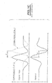
- the figure 1C represents, by way of illustration, an example of this principle in the case of a 2-PPM digital modulation, the transmission of binary values 0 and 1 being represented by the transmission of two pulses A and B offset temporally.
- the correlation pattern is designed so that the value of the cross-correlation coefficient is positive in the presence of an unshifted pulse (A), corresponding to the transmission of a zero but negative value in the presence of a shifted pulse (B) , corresponding to the transmission of a value one, and zero in the absence of pulses.
- the correlation pattern is thus symmetrical with respect to a center of asymmetry.
- FIG. figure 1D Another concrete example illustrated in the case of a PPM modulation with two simultaneous users each having a pseudo random sequence is represented in FIG. figure 1D .
- the symbol is repeated three times, each user thus emitting three pulses, representative of the same symbol.
- the symbol time T s is divided into three frames Tf in which each user codes a single single pulse.
- each pulse is shifted by a time interval ⁇ with respect to the beginning of each elementary frame interval when the bit transmission represented is that of the value 1 instead of the value 0, in the absence of an offset.
- Such receivers are therefore confined to high-end applications, for which the cost criterion is secondary vis-à-vis that of the overall quality performance of the link.
- UWB all-digital rake receiver solutions have been envisaged, in which the received signal is directly digitized at the antenna output. Although, because of purely signal processing software digitized supra, the structure of such receivers is no longer in connection with the traditional rake architecture, such solutions are not viable at present because the current analog-digital converters are not suitable for such use, and digital processing to perform on the aforementioned digital signals can not be performed in real time by the current digital signal processors.
- Another object of the present invention is the implementation of a method and a system for receiving a UWB signal by means of which the implementation costs are substantially reduced, because of the aforementioned simplification.
- Another object of the present invention is the implementation of a method and a system for receiving an ultra-broadband signal by which, despite the significant simplification of the structure used, an improvement in the quality Linkage and overall performance is significantly achieved due to the lack of hardware limitation in the number of main and secondary propagation paths actually handled.
- Another object of the present invention is, finally, because of the absence of hardware limitation of the number of main and secondary paths actually mentioned above, the implementation of a method and a system for receiving an ultra signal. a large band with a number of propagation paths actually treated as auto-adaptive, which makes it possible to optimize the quality of the radio link between transmitter and receiver, even in the presence of a transmission channel originating from a variable severe environment.
- the method and the UWB reception system, objects of the present invention find application to the radio link of domestic appliances or professionals of any type, especially in environment corresponding to a transmission channel over the air path that is substantially disturbed or variable.
- the receiving method of the invention receiving a sequence of successive modulated direct pulses over a symbol time T s , each pulse propagating along a direct propagation path with which a plurality of successive secondary impulses distinct, each propagating along a secondary propagation path distinct from the direct propagation path.
- each direct pulse corresponds to a shortest propagation time
- each distinct successive secondary pulse associated with the aforementioned direct pulse, then being successively shifted in time with respect to the moment of reception, of the direct impulse to which these latter are associated.
- the direct and secondary propagation paths in no way prejudge the number of reflections of the corresponding pulse propagating on these paths.
- the successive distinct secondary pulses are generated by a substantially increasing number of reflections, each reflection being the seat of attenuation.
- the successive distinct secondary pulses are considered to have a substantially decreasing amplitude or energy as a function of their reception rank.
- pulses ID ij are considered , these pulses corresponding, for example, to the pulses emitted, as represented in FIG. figure 1D when the modulation is of type 2-PPM for example.
- the index i denotes the user 1 or 2
- the index j denotes the rank of the pulse transmitted in each frame T f according to the pseudo-random code assigned to each user.
- the time shift ⁇ is the same as in the case of the figure 1 D for simplification.
- the method which is the subject of the invention then consists in receiving, in a step A, the succession of successive direct pulses modulated and the plurality of secondary pulses associated with each of the successive direct pulses modulated on the same receiving circuit.
- i and j represent the user reference, respectively the frame reference in the symbol time T s and k represents the rank of the received pulse, direct pulse and / or secondary pulse.
- the receiving step A is then followed by a step B consisting of generating, by calculation, a composite correlation pattern constituted by a sequence of elementary correlation patterns.
- each elementary correlation pattern corresponds, in the nonlimiting example of the 2-PPM modulation, to the so-called template signal represented in FIG. figure 1C .
- the sequence of elementary correlation patterns comprises a first elementary correlation pattern associated with each forward pulse, that is, any pulse corresponding in position in each frame T f to the position given by the pseudo-random code assigned to each user and, of course, successive elementary correlation patterns each associated with a successive secondary pulse of rank k, k ⁇ [1, N].
- the sliding secondary correlation detection of the set of direct or secondary pulses received over a symbol time is carried out by way of non-limiting example. It is indicated, in fact, that the calculation thus carried out on a symbol time can then be used for the next symbol time, due to the fact that, on a symbol time, where appropriate on two consecutive symbol times, the transmission channel is considered substantially invariable.
- the process of implementing and calculating the composite correlation pattern will be described in more detail in the description.
- Step B is then followed by a step C of calculating the value of the global intercorrelation coefficient
- GCC means the value of the overall cross-correlation coefficient obtained
- the value of the global intercorrelation coefficient GCC is thus constituted by the sum of the intercorrelation coefficients of each of the direct and secondary pulses obtained for each of the modulated pulses transmitted for the same symbol and represents a global correlation value of the symbol. transmitted for each user.
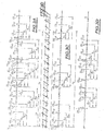
- the operation of calculating the global intercorrelation coefficient thus comprises, with reference to step C of the figure 2 the calculation of the elementary intercorrelation coefficient between each elemental intercorrelation pattern and the direct impulse respectively the secondary impulse associated with each of the elementary intercorrelation patterns, and then the integration, on the symbol time T s , of the set of elemental intercorrelation coefficient values.
- the process of calculating the value of the global intercorrelation coefficient GCC is then performed, as shown in FIG. Figures 3C , then 3D, for each of the users and, of course, for the direct pulses and the secondary pulses associated therewith from the composite correlation pattern, and the succession of the aforementioned pulses.
- the discrimination the rank of the secondary pulses is not essential, only the position of these pulses in a symbol time T s being finally taken into consideration.
- the method that is the subject of the present invention thus appears to be particularly remarkable in that the number of pulses finally retained for performing the computation operation of the composite correlation pattern and then the value of the overall intercorrelation coefficient can be high. and easily selected, for example, at a number of 10 secondary pulses for each direct pulse according to the characteristics of use and implementation of the method which is the subject of the invention,
- the choice of the number of pulses retained may be guided by considerations relating either to the amplitude and / or energy level of the secondary pulses or, more simply, to the number of pulses retained.
- the number of secondary pulses retained can consist in discriminating any direct pulse of the same frame and in retaining the secondary pulses between two successive direct pulses or even three successive direct pulses.
- the number of secondary pulses thus retained makes it possible to define and retain the first N paths.
- Another possibility for the choice of the number of secondary pulses may consist, for the countable set of direct pulses and secondary pulses considered, to retain N paths for which the amplitude or the energy of the direct pulse respectively secondary pulses are maximum.
- the number N of paths selected may be adapted either according to a selection criterion of the first N paths for execution of a faster processing or, on the contrary, according to a selection criterion of N paths corresponding to an amplitude. and / or a maximum energy of the direct pulse and secondary pulses depending on the propagation conditions.
- a mode of operation thus makes it possible to optimize the quality of the ultra-wideband signal link.
- this process consists, in fact, of establishing by correlation on at least one symbol time T s , an image of the transmission channel in terms of direct pulses and of secondary pulses of propagation time and difference in propagation time between direct pulses and successive secondary pulses, then to update, by sliding correlation, the image of the transmission channel to update the appearance and disappearance of paths of secondary propagation, the case appropriate direct propagation paths, and establish, over at least one symbol time, the composite correlation pattern as the updated image of the transmission channel.
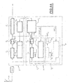
- the acquisition and updating channel 1 makes it possible, by sliding correlation, to update the appearance and disappearance of secondary propagation paths, as well as of the main propagation path and of course, to establish on at least one symbol time the composite correlation pattern previously mentioned in the description.
- the acquisition and updating channel 1 makes it possible to deliver a path list signal representative of the image of the transmission channel, the list of paths being denoted LT on the figure 4 , this list being delivered for example for each symbol time T s .
- the path list signal can correspond to the designation of the instants, on the symbol time, to which each elementary correlation pattern must be successively generated to achieve the aforementioned composite correlation pattern.
- the instants designated by the path list signal LT are, of course, offset in time with respect to the instant of the first elementary correlation pattern associated with each direct pulse of the difference in propagation time between the propagation time of the direct pulse on the direct propagation path and the propagation time of the associated secondary pulse propagating on the corresponding secondary propagation path.
- system which is the subject of the present invention comprises a single correlation channel 2 receiving the direct and secondary propagation path list signal LT, the unique correlation path 2 making it possible to calculate the value of the overall intercorrelation coefficient GCC.
- the aforementioned acquisition and updating channel 1 comprises a global acquisition correlation path and this path, denoted 1 1 receiving the sequence of successive pulses delivered by the common reception circuits and delivering a overall acquisition correlation coefficient value, denoted GAC 1 .
- the global acquisition correlation path 1 1 comprises a correlator 1 12 , an integrator or summator 1 13 and a generator 11 of the elementary synchronization pattern SEM 1 .
- the route of acquisition and updating 1 further comprises a module 1 0 exploration and tracking channel, which receives the global correlation coefficient value acquisition GAC 1 delivered by the global correlation pathway of acquisition and tracking 1 1 previously mentioned, as well as the value of the global intercorrelation coefficient GCC delivered by the path 2 of single correlation.
- Module 1 0 channel exploration and tracking outputs the direct propagation path list signal LT and secondary previously described in the description relating to the implementation of the method of the invention, as well as a signal synchronization ST 1 on the symbol time at the elementary synchronization pattern generator 1 11 constituting the acquisition and updating channel 1 1 .
- the generator of elementary synchronization patterns 11 delivers, after acquisition of the image of the sliding correlation channel, a set of elementary synchronization patterns SEM 1 forming an acquisition correlation pattern, which corresponds substantially to the existence of an elementary correlation pattern generated at the predictable moment of existence of each direct pulse or of secondary pulses associated therewith, in the absence of significant variability of the transmission channel.
- the synchronization signal ST 1 is, of course, synchronized to the symbol time.
- the channel exploration and tracking module 1 0 can, from the pseudo-random codes of each of the users, and therefore the position of the direct pulses generated by each of these, or from the list of paths LT, generating a synchronization signal ST 1 , as described above in the description.
- the selection of the instants of creation of the elementary synchronization patterns may be performed from the pseudo-random codes held by the elementary synchronization pattern generator 11 , the synchronization signal ST 1 then being reduced to a series of equidistant successive pulses constituting a time base for example, the equidistant pulses being separated by a time interval corresponding to the discrimination resolution of two successive direct and / or secondary pulses. These pulses are repeated at each symbol time T 5 .
- the aforesaid procedure enables the sliding path correlation list LT to be updated for the next symbol time from the value of the global correlation coefficient GCC delivered by the single correlation path for the preceding symbol time as a function of the appearance and / or disappearance of respectively secondary or direct propagation paths as a function of the variability of the transmission channel.
- the path list signal LT is substantially invariant from one symbol time to another.
- the acquisition correlation pattern delivered to the correlator January 12 is modified as well as, of course, the value of the corresponding global correlation coefficient GAC 1. .
- Comparing the values of the correlation coefficients GCC and GAC 1 then makes it possible to retain the modification of the acquisition correlation pattern and, of course, to update the path list signal LT for the following symbol time, in order to allow, finally, updating the correlation process of the unique correlation path 2.
- the path list signal LT delivered by the exploration module and channel tracking is formed by the instants of composite correlation with the sequence of successive pulses received, for which the value of the overall intercorrelation coefficient GCC delivered by the single correlation path is maximum.
- the single correlation path 2 comprises a reception control circuit 20 receiving the path list signal LT described above and a generator of correlation elementary patterns 2 1 receiving the signal delivered by the reception control module 2. 0 .
- the elementary correlation pattern generator 21 delivers the composite correlation pattern 2 1 .
- reception control module 20 With regard to the reception control module 20 , it is indicated that the latter, from the path list signal LT, makes it possible to deliver a series of trigger pulses corresponding to the correlation instants previously defined in the description.
- the pulse sequence thus obtained makes it possible to obtain the composite correlation pattern from elementary correlation patterns generated for each trigger pulse delivered by the control and reception module 20 .
- FIG. Figure 4A it may comprise a plurality of global correlation acquisition and tracking paths, the channels 1 1 previously described and 1 2 shown in dashed lines.
- the global acquisition and tracking correlation path (s) are identical to channel 1, previously described, and for this reason have similar reference elements, 1 22 for the correlator, 1 23 for the integrator or summator, 1 21 for the elementary synchronization pattern generator, SEM 2 for the basic synchronization patterns.
- Two global correlation acquisition channels and tracking or more may be provided, the scanning module and channel tracking 1 0 being common to all of the above ways.
- the channel exploration and tracking module 1 0 receives the value of the corresponding global acquisition correlation coefficients referenced GAC 1 , GAC 2 on the Figure 4A , but delivers, by cor tre, a plurality of synchronization signals ST 1 , ST 2 , as mentioned in the aforementioned figure.
- each global acquisition and tracking correlation channel 1 1 1 2 and of subsequent rank comprises a generator of elementary synchronization patterns 1 11 and 1 21 which is specific to it.
- Each of these latter receives a list signal of the specific correlation instants delivered by the channel exploration and tracking module 1 0 , that is to say the signals ST 1 and ST 2 and following.
- These signals may advantageously correspond to offset time slots, such as frame slots for example, these slots being successive and complementary. This makes it possible to generate a sequence of successive elementary correlation patterns of synchronization by successive complementary time slots, by sliding correlation, and to divide, thus, the acquisition time of the image of the transmission channel by the number of channels of global correlation of acquisition and tracking constituting the plurality of global correlation acquisition and tracking paths.
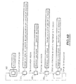
- an initialization step 100 is called, in which the receiving system represented in Figure 4A is initialized, in particular, the calculation values are all reset for example.
- Step 100 is followed, after initialization is completed, of a channel polling step 101 and a sliding correlation synchronization search, as previously mentioned in the description.
- This step is carried out, as described previously in the description, from the pseudo-random codes used to each of the users, and, of course, from the position of the pulses received, transmitted and therefore received, taking into account the pseudo-random code. supra.
- the appearance of a main correlation peak makes it possible to synchronize the receiver system which is the subject of the invention, as represented in FIG. Figure 4A on the transmitter, detecting and marking the main path, following detection of the position of each main pulse. In this situation, the secondary correlation peaks, revealing the existence of secondary propagation paths, are then detected and the value of the correlation coefficient Global GCC and GAC Global Acquisition Correlation Coefficient are then updated accordingly.
- the channel exploration and tracking module 1 0 then makes it possible to encrypt the paths to be processed, to assign them, possibly, a weighting coefficient, in the same way as in the case of the devices of the prior art, and note the respective propagation time as mentioned previously in the description for successive pulses.
- the selection of the paths can be carried out either by retaining the N strongest paths or the first N paths or, where appropriate, a compromise between the two.
- the step 101 is followed by a single-path reception step 102 during which the selection of the paths can be performed.
- a particularly advantageous selection process may consist in processing the first arrived path, then adding the following paths one by one until the taking into account of additional paths no longer increases the signal ratio. to global noise.
- the single-path reception is acquired, that is to say reception of the main paths, and the selection of the propagation paths of the secondary pulses is also established, the aforementioned selection is then exploitable.
- one of the correlators thus operates in reception, while the correlator 1 12 of the acquisition correlation and tracking 1 1 1 operates by sliding correlation in order to keep the image of the transmission channel up to date.
- This operation is carried out at step 103 of the Figure 4B , the reception then being performed in multi-path.
- the channel exploration and tracking module makes it possible to detect the appearance or disappearance of propagation paths, as well as to continue the aforementioned paths.
- the continuation of the paths can be carried out according to the criterion of energy or signal-to-noise ratio mentioned previously in the description.
- the channel exploration and tracking module 1 0 thus makes it possible to ensure a dynamic processing of the paths, to assign and modify the weighting coefficients when they are used and to change the list of paths processed, the path list signal LT being air if modified for updating.
- the operation 103 is followed by a multi-path reception operation 104 consisting in updating the selection of the paths, that is to say of the list of the paths LT.
- the return arrow from step 104 to step 103, on the Figure 4B illustrates the continuous nature of multi-path reception and, of course, channel scanning and updating of the LT path list.
- this weighting operation can be implemented at the level of the elementary correlation pattern generator 2 1 of the single global correlation path 2, at each elementary pattern can then be applied, at the aforementioned generator 2 1 , an amplitude proportional to the weighting coefficient of the associated path.
- a device for controlling the amplitude of the pattern shown at 2a in the drawing, can be added if necessary.
- the number of correlation channels can be substantially reduced to two, a single correlation channel ensuring the reception properly. said and a global correlation acquisition path, as described above.
- the method and the system that are the subject of the invention appear particularly advantageous insofar as the number of paths processed is adaptive, the adaptive character resulting from the possibility of choosing and adapting the number of reception paths processed during operation. .
- a receiver according to the object of the present invention is able to modify its characteristics dynamically and therefore to adapt ideally to the operating conditions dictated by the qualities of the parameters, such as quality of connection, constraints of autonomy and variability of the transmission channel.
- the number of paths processed is not limited by hardware execution contingencies but, on the contrary, by signal-to-noise or specific energy value value criteria, for example.
Landscapes
- Engineering & Computer Science (AREA)
- Computer Networks & Wireless Communication (AREA)
- Signal Processing (AREA)
- Radar Systems Or Details Thereof (AREA)
- Synchronisation In Digital Transmission Systems (AREA)
- Monitoring And Testing Of Transmission In General (AREA)
- Cable Transmission Systems, Equalization Of Radio And Reduction Of Echo (AREA)
- Circuits Of Receivers In General (AREA)
Claims (11)
- Verfahren zum Empfang eines für Symbole repräsentativen Ultrabreitbandsignals, wobei dieses auf einem Übertragungskanal übertragene Signal über eine Symbolzeit eine Folge von modulierten aufeinanderfolgenden direkten Impulsen für das gleiche Symbol, wobei jeder direkte Impuls sich gemäß einem direkten Ausbreitungsweg ausbreitet, aufweist, der mehrere unterschiedliche aufeinanderfolgende sekundäre Impulse zugeordnet sind, die sich je gemäß einem sekundären Ausbreitungsweg ausbreiten, dadurch gekennzeichnet, dass, da die Folge von modulierten aufeinanderfolgenden direkten Impulsen und die jedem der modulierten aufeinanderfolgenden direkten Impulse zugeordneten mehreren sekundären Impulse in der gleichen Empfangsschaltung empfangen werden, die darin besteht:- ein zusammengesetztes Korrelationsmuster zu erzeugen, das aus einer Folge von elementaren Korrelationsmustern besteht, wobei die Folge von elementaren Korrelationsmustern aufweist:+ für jeden direkten Impuls ein erstes elementares Korrelationsmuster, das diesem direkten Impuls zugeordnet ist, und+ für jeden direkten Impuls aufeinanderfolgende elementare Korrelationsmuster, die je einem aufeinanderfolgenden sekundären Impuls des direkten Impulses zugeordnet sind, wobei die aufeinanderfolgenden elementaren Korrelationsmuster zeitlich bezüglich des ersten elementaren Korrelationsmusters um die Ausbreitungszeitdifferenz zwischen der Ausbreitungszeit des direkten Impulses auf dem direkten Ausbreitungsweg und der Ausbreitungszeit des zugeordneten sekundären Impulses verschoben sind, der sich auf dem entsprechenden sekundären Ausbreitungsweg ausbreitet;- das Ultrabreitbandsignal und das zusammengesetzte Korrelationsmuster an einen Korrelator zu liefern, um einen elementaren Interkorrelationskoeffizient zwischen jedem elementaren Interkorrelationsmuster und dem diesem elementaren Interkorrelationsmuster zugeordneten direkten Impuls bzw. sekundären Impuls zu berechnen;- über die Symbolzeit die Gesamtheit der elementaren Interkorrelationskoeffizientenwerte zu integrieren, um einen globalen Interkorrelationskoeffizientenwert zu liefern, der für einen globalen Korrelationswert des Symbols repräsentativ ist.
- Verfahren nach Anspruch 1, dadurch gekennzeichnet, dass für eine zählbare Einheit von Impulsen, einem direkten Impuls und sekundären Impulsen, die sich auf einem direkten Weg bzw. auf einem sekundären Weg mehrerer sekundärer Ausbreitungswege ausbreiten, das Verfahren darin besteht, die N ersten Wege zu wählen, wobei die N ersten Wege den direkten Weg, der einer geringsten Ausbreitungszeit des zugeordneten modulierten Impulses entspricht, und N-1 sekundäre Wege aufweisen, die je einer Ausbreitungszeit eines sekundären Impulses entsprechen, die nacheinander zunimmt.
- Verfahren nach einem der Ansprüche 1 oder 2, dadurch gekennzeichnet, dass für eine zählbare Einheit von Impulsen, einem direkten Impuls und sekundären Impulsen, die sich auf einem direkten Weg bzw. auf einem sekundären Weg mehrerer sekundärer Ausbreitungswege ausbreiten, das Verfahren darin besteht, N Wege zu wählen, für die die Amplitude des direkten Impulses bzw. der sekundären Impulse maximal ist.
- Verfahren nach einem der Ansprüche 2 oder 3, dadurch gekennzeichnet, dass die Anzahl N von gewählten Wegen entweder gemäß einem Auswahlkriterium der N ersten Wege oder gemäß einem Auswahlkriterium der N Wege, die einer maximalen Amplitude des direkten Impulses bzw. der sekundären Impulse in Abhängigkeit von den Ausbreitungsbedingungen entsprechen, angepasst wird, was es ermöglicht, die Qualität der Verbindung durch Ultrabreitbandsignal zu optimieren.
- Verfahren nach einem der Ansprüche 1 bis 4,
dadurch gekennzeichnet, dass der Schritt, der darin besteht, ein zusammengesetztes Korrelationsmuster zu erzeugen, darin besteht:- durch Korrelation über mindestens eine Symbolzeit ein Bild des Übertragungskanals im Hinblick auf einen direkten Impuls bzw. sekundäre Impulse, die Ausbreitungszeit und die Ausbreitungszeitdifferenz zwischen direktem Impuls und aufeinanderfolgenden sekundären Impulsen festzulegen;- durch gleitende Korrelation das Bild des Übertragungskanals auf den neuesten Stand zu bringen, um das Auftreten und das Verschwinden von sekundären Ausbreitungswegen und/oder des direkten Ausbreitungswegs zu aktualisieren und über mindestens eine Symbolzeit das zusammengesetzte Korrelationsmuster als das aktualisierte Bild des Übertragungskanals festzulegen. - System zum Empfang eines für Symbole repräsentativen Ultrabreitbandsignals, wobei dieses auf einem Übertragungskanal übertragene Signal über eine Symbolzeit eine Folge von modulierten aufeinanderfolgenden direkten Impulsen für das gleiche Symbol, wobei jeder direkte Impuls sich gemäß einem direkten Ausbreitungsweg ausbreitet, aufweist, der mehrere unterschiedliche aufeinanderfolgende sekundäre Impulse zugeordnet sind, die sich je gemäß einem sekundären Ausbreitungsweg ausbreiten, dadurch gekennzeichnet, dass es mindestens aufweist:- gemeinsame Empfangsmittel der Folge von modulierten aufeinanderfolgenden Impulsen und der mehreren sekundären Impulse, die jedem der modulierten aufeinanderfolgenden direkten Impulse zugeordnet sind, und mit den gemeinsamen Empfangsmitteln verbunden sind,- einen Pfad der Erfassung und Aktualisierung über mindestens eine Symbolzeit eines Bilds des Übertragungskanals im Hinblick auf den direkten Impuls bzw. die sekundären Impulse, die Ausbreitungszeit und die Ausbreitungszeitdifferenz zwischen direktem Impuls und aufeinanderfolgenden sekundären Impulsen, wobei der Erfassungs- und Aktualisierungspfad es durch gleitende Korrelation ermöglicht, eine Aktualisierung des Auftretens und des Verschwindens von sekundären Ausbreitungswegen und/oder des Hauptausbreitungswegs zu gewährleisten,+ für jeden direkten Impuls ein erstes elementares Korrelationsmuster, das diesem direkten Impuls zugeordnet ist, und+ für jeden direkten Impuls aufeinanderfolgende elementare Korrelationsmuster, die je einem der aufeinanderfolgenden sekundären Impulse des direkten Impulses zugeordnet sind, wobei die aufeinanderfolgenden elementaren Korrelationsmuster zeitlich bezüglich des ersten elementaren Korrelationsmusters um die Ausbreitungszeitdifferenz zwischen der Ausbreitungszeit des direkten Impulses auf dem direkten Ausbreitungsweg und der Ausbreitungszeit des zugeordneten sekundären Impulses verschoben sind, der sich auf dem entsprechenden sekundären Ausbreitungsweg ausbreitet;- einen Korrelationspfad, der das Listensignal von direkten bzw. sekundären Ausbreitungswegen empfängt, wobei der Korrelationspfad fähig ist, über mindestens eine Symbolzeit ein zusammengesetztes Korrelationsmuster festzulegen, das aus einer Folge von elementaren Korrelationsmustern besteht, wobei der Korrelationspfad einen einzigen Korrelator aufweist, der das Ultrabreitbandsignal und das zusammengesetzte Korrelationsmuster empfängt, um einen elementaren Interkorrelationskoeffizient zwischen jedem elementaren Interkorrelationsmuster und dem diesem elementaren Interkorrelationsmuster zugeordneten direkten Impuls bzw. sekundären Impuls zu berechnen, und der Korrelationspfad einen Summierer aufweist, um über die Symbolzeit die Gesamtheit der elementaren Interkorrelationskoeffizientenwerte zu integrieren, um einen globalen Interkorrelationskoeffizientenwert zu liefern, der für einen globalen Korrelationswert des Symbols repräsentativ ist.
- System nach Anspruch 6, dadurch gekennzeichnet, dass der Erfassungs- und Aktualisierungspfad aufweist:- mindestens einen globalen Erfassungs- und Verfolgungs-Korrelationspfad, der die empfangene Folge von aufeinanderfolgenden Impulsen empfängt, die von den gemeinsamen Empfangsmitteln geliefert wird, und einen globalen Erfassungs-Korrelationskoeffizientenwert liefert;- ein Abtast- und Verfolgungsmodul des Kanals, das mindestens den globalen Erfassungs-Korrelationskoeffizientenwert und den globalen Korrelationskoeffizientenwert empfängt und einerseits das Listensignal von direkten und sekundären Ausbreitungswegen und andererseits ein Synchronisationssignal an den globalen Erfassungs- und Verfolgungs-Korrelationspfad liefert.
- System nach Anspruch 7, dadurch gekennzeichnet, dass der globale Erfassungs- und Verfolgungs-Korrelationspfad aufweist:- einen Korrelator, der die empfangene Folge von aufeinanderfolgenden Impulsen empfängt, und einen Summierer, der den Erfassungs-Korrelationskoeffizientenwert liefert;- einen Generator von elementaren Synchronisationsmustern, der das Synchronisationssignal empfängt und ein Erfassungs-Korrelationsmuster an den Korrelator liefert, wobei das Synchronisationssignal aus einer Folge von Momenten von aufeinanderfolgenden elementaren Korrelationsmustern besteht, was es ermöglicht, das Wege-Listensignal durch gleitende Korrelation für die folgende Symbolzeit durch gleitende Korrelation ausgehend von dem globalen Wert des Korrelationskoeffizienten zu aktualisieren, der vom einzigen Korrelationspfad für die vorhergehende Symbolzeit geliefert wird, in Abhängigkeit vom Auftreten bzw. Verschwinden von direkten bzw. sekundären Ausbreitungswegen, in Abhängigkeit von der Variabilität des Übertragungskanals.
- System nach einem der Ansprüche 6 bis 8, dadurch gekennzeichnet, dass das Wege-Listensignal, das vom Kanal-Abtast- und Verfolgungsmodul geliefert wird, von den Momenten der zusammengesetzten Korrelation mit der empfangenen Folge von aufeinanderfolgenden Impulsen geformt wird, für die der vom einzigen Korrelationspfad gelieferte Wert des globalen Interkorrelationskoeffizienten maximal ist.
- System nach einem der Ansprüche 7 bis 9, dadurch gekennzeichnet, dass es mehrere Pfade der globalen Erfassungs- und Verfolgungskorrelation aufweist, die die empfangene Folge von aufeinanderfolgenden Impulsen empfangen, wobei jeder Pfad der globalen Erfassungs- und Verfolgungskorrelation einem Generator von elementaren Synchronisationsmustern zugeordnet ist, wobei die von einem Pfad der globalen Erfassungs- und Verfolgungskorrelation und von dem diesem zugeordneten Generator eines elementaren Musters gebildete Einheit ein Listensignal der spezifischen Korrelationsmomente empfängt, das vom Kanal-Abtast- und Verfolgungsmodul geliefert wird, wobei die Listensignale der spezifischen Korrelationsmomente verschobenen Zeitabschnitten entsprechen, was es ermöglicht, eine Folge von aufeinanderfolgenden elementaren Korrelationsmustern in komplementären aufeinanderfolgenden Zeitabschnitten durch gleitende Korrelation zu erzeugen und im Wesentlichen die Erfassungszeit des Bilds des Übertragungskanals durch die Anzahl von Pfaden globaler Erfassungs- und Verfolgungskorrelation zu dividieren, die die mehreren Pfade der globalen Erfassungs- und Verfolgungskorrelation bilden.
- System nach einem der Ansprüche 6 bis 10, dadurch gekennzeichnet, dass der einzige Korrelationspfad mindestens aufweist:- einen Generator von elementaren Korrelationsmustern, und- diesem Generator zugeordnet ein Gewichtungsmodul mindestens eines der elementaren Korrelationsmuster, die das zusammengesetzte Korrelationsmuster bilden.
Applications Claiming Priority (3)
| Application Number | Priority Date | Filing Date | Title |
|---|---|---|---|
| FR0216027A FR2848746A1 (fr) | 2002-12-17 | 2002-12-17 | Procede et systeme de reception d'un signal ultra-large bande a nombre de trajets de propagation auto-adaptatif |
| FR0216027 | 2002-12-17 | ||
| PCT/FR2003/003724 WO2004066517A1 (fr) | 2002-12-17 | 2003-12-15 | Procede et systeme de reception d'un signal ultra-large bande a nombre de trajets de propagation auto-adaptatif |
Publications (2)
| Publication Number | Publication Date |
|---|---|
| EP1573933A1 EP1573933A1 (de) | 2005-09-14 |
| EP1573933B1 true EP1573933B1 (de) | 2008-10-22 |
Family
ID=32338910
Family Applications (1)
| Application Number | Title | Priority Date | Filing Date |
|---|---|---|---|
| EP03815405A Expired - Lifetime EP1573933B1 (de) | 2002-12-17 | 2003-12-15 | Verfahren und system zum empfangen eines Ultrabreitbandsignals mit selbstanpassender Anzahl von Ausbreitungswegen |
Country Status (11)
| Country | Link |
|---|---|
| US (1) | US7362743B2 (de) |
| EP (1) | EP1573933B1 (de) |
| JP (1) | JP4468822B2 (de) |
| CN (1) | CN100420160C (de) |
| AT (1) | ATE412272T1 (de) |
| AU (1) | AU2003300613A1 (de) |
| BR (1) | BR0316893A (de) |
| DE (1) | DE60324323D1 (de) |
| ES (1) | ES2314293T3 (de) |
| FR (1) | FR2848746A1 (de) |
| WO (1) | WO2004066517A1 (de) |
Families Citing this family (3)
| Publication number | Priority date | Publication date | Assignee | Title |
|---|---|---|---|---|
| FR2893465A1 (fr) * | 2005-11-14 | 2007-05-18 | France Telecom | Procede de detection de trajets en transmission impulsionnelle et dispositif correspondant. |
| US20080182574A1 (en) * | 2007-01-25 | 2008-07-31 | Telefonaktiebolaget L M Ericsson (Publ) | Ultra-Wideband Mode Selection |
| EP2156569B1 (de) * | 2007-05-11 | 2021-11-24 | Commissariat à l'Énergie Atomique et aux Énergies Alternatives | Verfahren zur verarbeitung von ultrabreitbandigen gleichgerichteten abgetasteten signalen |
Family Cites Families (8)
| Publication number | Priority date | Publication date | Assignee | Title |
|---|---|---|---|---|
| US5677927A (en) * | 1994-09-20 | 1997-10-14 | Pulson Communications Corporation | Ultrawide-band communication system and method |
| JP3283210B2 (ja) * | 1997-05-30 | 2002-05-20 | 株式会社鷹山 | スペクトラム拡散通信方式における信号受信装置 |
| US6810087B2 (en) * | 2000-01-04 | 2004-10-26 | General Electric Company | Ultra-wideband communications system |
| CN1111325C (zh) * | 2000-03-24 | 2003-06-11 | 信息产业部电信传输研究所 | 一种宽带码分多址系统中的多径筛选方法 |
| AU2001247865A1 (en) * | 2000-03-29 | 2001-10-15 | Time Domain Corporation | System and method of using multiple correlator receivers in an impulse radio system |
| US6967993B1 (en) * | 2000-05-26 | 2005-11-22 | Freescale Semiconductor, Inc. | Ultrawide bandwidth system and method for fast synchronization using sub-code spins |
| US7366268B2 (en) * | 2002-12-02 | 2008-04-29 | Matsushita Electric Industrial Co., Ltd. | Selective data inversion in ultra-wide band communications to eliminate line frequencies |
| FR2855684B1 (fr) * | 2003-05-26 | 2005-07-01 | Commissariat Energie Atomique | Recepteur de signal ultra large bande et procede de reception associe. |
-
2002
- 2002-12-17 FR FR0216027A patent/FR2848746A1/fr active Pending
-
2003
- 2003-12-15 DE DE60324323T patent/DE60324323D1/de not_active Expired - Lifetime
- 2003-12-15 AT AT03815405T patent/ATE412272T1/de not_active IP Right Cessation
- 2003-12-15 ES ES03815405T patent/ES2314293T3/es not_active Expired - Lifetime
- 2003-12-15 CN CNB2003801065893A patent/CN100420160C/zh not_active Expired - Lifetime
- 2003-12-15 AU AU2003300613A patent/AU2003300613A1/en not_active Abandoned
- 2003-12-15 WO PCT/FR2003/003724 patent/WO2004066517A1/fr not_active Ceased
- 2003-12-15 EP EP03815405A patent/EP1573933B1/de not_active Expired - Lifetime
- 2003-12-15 BR BR0316893-0A patent/BR0316893A/pt not_active Application Discontinuation
- 2003-12-15 JP JP2004567003A patent/JP4468822B2/ja not_active Expired - Lifetime
- 2003-12-15 US US10/539,631 patent/US7362743B2/en not_active Expired - Lifetime
Also Published As
| Publication number | Publication date |
|---|---|
| ATE412272T1 (de) | 2008-11-15 |
| ES2314293T3 (es) | 2009-03-16 |
| CN100420160C (zh) | 2008-09-17 |
| FR2848746A1 (fr) | 2004-06-18 |
| AU2003300613A1 (en) | 2004-08-13 |
| DE60324323D1 (de) | 2008-12-04 |
| US20060154630A1 (en) | 2006-07-13 |
| JP4468822B2 (ja) | 2010-05-26 |
| WO2004066517A1 (fr) | 2004-08-05 |
| CN1726653A (zh) | 2006-01-25 |
| US7362743B2 (en) | 2008-04-22 |
| JP2006511178A (ja) | 2006-03-30 |
| EP1573933A1 (de) | 2005-09-14 |
| BR0316893A (pt) | 2005-10-25 |
Similar Documents
| Publication | Publication Date | Title |
|---|---|---|
| EP0738049B1 (de) | Spreizspektrumsignalempfänger unter Verwendung einer selbsteinstellenden Detektionsschwelle | |
| FR2715523A1 (fr) | Récepteur et procédé de réception pour un système d'accès multiple par répartition par code. | |
| FR2774831A1 (fr) | Recepteur adaptatif de signaux pour systeme de communications a acces pultiples par repartition a codes | |
| FR2713421A1 (fr) | Réseau local à transmission radio. | |
| FR2813465A1 (fr) | Methode d'estimation conjointe de canal et de direction d'arrivee | |
| WO2001099301A1 (fr) | Procede et dispositif d'annulation de l'interference dans un recepteur | |
| EP1553426A1 (de) | Verfahren und Empfänger zur ultrabreitbandigen und drahtlosen Datenübertragung mit zeitkodierten Signalen | |
| EP1260071A1 (de) | Verfahren und vorrichtung für kanalschäztung | |
| EP0917299B1 (de) | Digitale Direktsequenzspreizspektrumnachrichtenübertragung mit Störsignalgeneration | |
| EP0820157B1 (de) | Verfahren zur digitalen Differenzialdemodulation | |
| EP1573933B1 (de) | Verfahren und system zum empfangen eines Ultrabreitbandsignals mit selbstanpassender Anzahl von Ausbreitungswegen | |
| EP1482648A1 (de) | Ultrabreitbandempfänger und entsprechendes Empfangsverfahren | |
| EP0917298B1 (de) | Differentieller Direktsequenzspreizspektrumempfänger mit gemischter Störsignalerzeugungsvorrichtung | |
| EP1972068B1 (de) | Verfahren zur symboldetektion sowie entsprechender empfänger | |
| EP1135855B1 (de) | Digitales filter mit paralleler architektur und spreizspektrumempfänger mit einem solchen filter | |
| EP3503413A1 (de) | Multiantennen-impuls-uwb-empfänger | |
| EP0911991B1 (de) | Verfahren zur Spreizspektrumsignalübertragungsverarbeitung und entsprechender Empfänger | |
| EP1041730B1 (de) | Empfangsmodul und Empfänger bestehend aus meheren kaskadierten Modulen | |
| EP0994580B1 (de) | Übertragungsverfahren in einem Funkkommunikationssystem mit Vielfachzugriff | |
| EP1065797B1 (de) | CDMA-Empfänger mit paralleler Interferenzunterdrückung und optimierter Synchronisation | |
| EP1252722B1 (de) | Cdma-funkübertragungsverfahren mit zugriffskodes und empfänger dafür | |
| WO2005109708A1 (fr) | Procede de determination de codes d’etalement utilises dans un signal cdma et dispositif de communication correspondant. | |
| EP1346489A1 (de) | Vorrichtung zum austauschen von digitalen daten in einem cdma system | |
| EP1084535A1 (de) | Empfänger für cdma-system | |
| FR2979775A1 (fr) | Procede de synchronisation et de reception d'un recepteur radio, et recepteur adapte pour mettre en oeuvre un tel procede |
Legal Events
| Date | Code | Title | Description |
|---|---|---|---|
| PUAI | Public reference made under article 153(3) epc to a published international application that has entered the european phase |
Free format text: ORIGINAL CODE: 0009012 |
|
| 17P | Request for examination filed |
Effective date: 20050610 |
|
| AK | Designated contracting states |
Kind code of ref document: A1 Designated state(s): AT BE BG CH CY CZ DE DK EE ES FI FR GB GR HU IE IT LI LU MC NL PT RO SE SI SK TR |
|
| AX | Request for extension of the european patent |
Extension state: AL LT LV MK |
|
| DAX | Request for extension of the european patent (deleted) | ||
| 17Q | First examination report despatched |
Effective date: 20061025 |
|
| GRAP | Despatch of communication of intention to grant a patent |
Free format text: ORIGINAL CODE: EPIDOSNIGR1 |
|
| RTI1 | Title (correction) |
Free format text: METHOD AND SYSTEM FOR RECEIVING AN ULTRA-WIDEBAND SIGNAL WITH A SELF-ADAPTING NUMBER OF PROPAGATION PATHS |
|
| GRAS | Grant fee paid |
Free format text: ORIGINAL CODE: EPIDOSNIGR3 |
|
| GRAA | (expected) grant |
Free format text: ORIGINAL CODE: 0009210 |
|
| AK | Designated contracting states |
Kind code of ref document: B1 Designated state(s): AT BE BG CH CY CZ DE DK EE ES FI FR GB GR HU IE IT LI LU MC NL PT RO SE SI SK TR |
|
| REG | Reference to a national code |
Ref country code: GB Ref legal event code: FG4D Free format text: NOT ENGLISH |
|
| REG | Reference to a national code |
Ref country code: CH Ref legal event code: EP |
|
| REG | Reference to a national code |
Ref country code: IE Ref legal event code: FG4D Free format text: LANGUAGE OF EP DOCUMENT: FRENCH |
|
| REF | Corresponds to: |
Ref document number: 60324323 Country of ref document: DE Date of ref document: 20081204 Kind code of ref document: P |
|
| REG | Reference to a national code |
Ref country code: ES Ref legal event code: FG2A Ref document number: 2314293 Country of ref document: ES Kind code of ref document: T3 |
|
| NLV1 | Nl: lapsed or annulled due to failure to fulfill the requirements of art. 29p and 29m of the patents act | ||
| PG25 | Lapsed in a contracting state [announced via postgrant information from national office to epo] |
Ref country code: BG Free format text: LAPSE BECAUSE OF FAILURE TO SUBMIT A TRANSLATION OF THE DESCRIPTION OR TO PAY THE FEE WITHIN THE PRESCRIBED TIME-LIMIT Effective date: 20090122 Ref country code: AT Free format text: LAPSE BECAUSE OF FAILURE TO SUBMIT A TRANSLATION OF THE DESCRIPTION OR TO PAY THE FEE WITHIN THE PRESCRIBED TIME-LIMIT Effective date: 20081022 |
|
| PG25 | Lapsed in a contracting state [announced via postgrant information from national office to epo] |
Ref country code: PT Free format text: LAPSE BECAUSE OF FAILURE TO SUBMIT A TRANSLATION OF THE DESCRIPTION OR TO PAY THE FEE WITHIN THE PRESCRIBED TIME-LIMIT Effective date: 20090323 Ref country code: SI Free format text: LAPSE BECAUSE OF FAILURE TO SUBMIT A TRANSLATION OF THE DESCRIPTION OR TO PAY THE FEE WITHIN THE PRESCRIBED TIME-LIMIT Effective date: 20081022 Ref country code: FI Free format text: LAPSE BECAUSE OF FAILURE TO SUBMIT A TRANSLATION OF THE DESCRIPTION OR TO PAY THE FEE WITHIN THE PRESCRIBED TIME-LIMIT Effective date: 20081022 Ref country code: NL Free format text: LAPSE BECAUSE OF FAILURE TO SUBMIT A TRANSLATION OF THE DESCRIPTION OR TO PAY THE FEE WITHIN THE PRESCRIBED TIME-LIMIT Effective date: 20081022 |
|
| BERE | Be: lapsed |
Owner name: FRANCE TELECOM Effective date: 20081231 |
|
| REG | Reference to a national code |
Ref country code: IE Ref legal event code: FD4D |
|
| PG25 | Lapsed in a contracting state [announced via postgrant information from national office to epo] |
Ref country code: RO Free format text: LAPSE BECAUSE OF FAILURE TO SUBMIT A TRANSLATION OF THE DESCRIPTION OR TO PAY THE FEE WITHIN THE PRESCRIBED TIME-LIMIT Effective date: 20081022 Ref country code: MC Free format text: LAPSE BECAUSE OF NON-PAYMENT OF DUE FEES Effective date: 20081231 Ref country code: EE Free format text: LAPSE BECAUSE OF FAILURE TO SUBMIT A TRANSLATION OF THE DESCRIPTION OR TO PAY THE FEE WITHIN THE PRESCRIBED TIME-LIMIT Effective date: 20081022 Ref country code: IE Free format text: LAPSE BECAUSE OF FAILURE TO SUBMIT A TRANSLATION OF THE DESCRIPTION OR TO PAY THE FEE WITHIN THE PRESCRIBED TIME-LIMIT Effective date: 20081022 Ref country code: DK Free format text: LAPSE BECAUSE OF FAILURE TO SUBMIT A TRANSLATION OF THE DESCRIPTION OR TO PAY THE FEE WITHIN THE PRESCRIBED TIME-LIMIT Effective date: 20081022 |
|
| REG | Reference to a national code |
Ref country code: CH Ref legal event code: PL |
|
| PLBE | No opposition filed within time limit |
Free format text: ORIGINAL CODE: 0009261 |
|
| STAA | Information on the status of an ep patent application or granted ep patent |
Free format text: STATUS: NO OPPOSITION FILED WITHIN TIME LIMIT |
|
| PG25 | Lapsed in a contracting state [announced via postgrant information from national office to epo] |
Ref country code: SE Free format text: LAPSE BECAUSE OF FAILURE TO SUBMIT A TRANSLATION OF THE DESCRIPTION OR TO PAY THE FEE WITHIN THE PRESCRIBED TIME-LIMIT Effective date: 20090122 Ref country code: CZ Free format text: LAPSE BECAUSE OF FAILURE TO SUBMIT A TRANSLATION OF THE DESCRIPTION OR TO PAY THE FEE WITHIN THE PRESCRIBED TIME-LIMIT Effective date: 20081022 |
|
| 26N | No opposition filed |
Effective date: 20090723 |
|
| PG25 | Lapsed in a contracting state [announced via postgrant information from national office to epo] |
Ref country code: SK Free format text: LAPSE BECAUSE OF FAILURE TO SUBMIT A TRANSLATION OF THE DESCRIPTION OR TO PAY THE FEE WITHIN THE PRESCRIBED TIME-LIMIT Effective date: 20081022 Ref country code: BE Free format text: LAPSE BECAUSE OF NON-PAYMENT OF DUE FEES Effective date: 20081231 |
|
| PG25 | Lapsed in a contracting state [announced via postgrant information from national office to epo] |
Ref country code: LI Free format text: LAPSE BECAUSE OF NON-PAYMENT OF DUE FEES Effective date: 20081231 Ref country code: CH Free format text: LAPSE BECAUSE OF NON-PAYMENT OF DUE FEES Effective date: 20081231 |
|
| PG25 | Lapsed in a contracting state [announced via postgrant information from national office to epo] |
Ref country code: LU Free format text: LAPSE BECAUSE OF NON-PAYMENT OF DUE FEES Effective date: 20081215 Ref country code: HU Free format text: LAPSE BECAUSE OF FAILURE TO SUBMIT A TRANSLATION OF THE DESCRIPTION OR TO PAY THE FEE WITHIN THE PRESCRIBED TIME-LIMIT Effective date: 20090423 Ref country code: CY Free format text: LAPSE BECAUSE OF FAILURE TO SUBMIT A TRANSLATION OF THE DESCRIPTION OR TO PAY THE FEE WITHIN THE PRESCRIBED TIME-LIMIT Effective date: 20081022 |
|
| PG25 | Lapsed in a contracting state [announced via postgrant information from national office to epo] |
Ref country code: TR Free format text: LAPSE BECAUSE OF FAILURE TO SUBMIT A TRANSLATION OF THE DESCRIPTION OR TO PAY THE FEE WITHIN THE PRESCRIBED TIME-LIMIT Effective date: 20081022 |
|
| PG25 | Lapsed in a contracting state [announced via postgrant information from national office to epo] |
Ref country code: GR Free format text: LAPSE BECAUSE OF FAILURE TO SUBMIT A TRANSLATION OF THE DESCRIPTION OR TO PAY THE FEE WITHIN THE PRESCRIBED TIME-LIMIT Effective date: 20090123 |
|
| REG | Reference to a national code |
Ref country code: FR Ref legal event code: PLFP Year of fee payment: 13 |
|
| REG | Reference to a national code |
Ref country code: FR Ref legal event code: PLFP Year of fee payment: 14 |
|
| REG | Reference to a national code |
Ref country code: FR Ref legal event code: PLFP Year of fee payment: 15 |
|
| PGFP | Annual fee paid to national office [announced via postgrant information from national office to epo] |
Ref country code: IT Payment date: 20221122 Year of fee payment: 20 Ref country code: GB Payment date: 20221116 Year of fee payment: 20 Ref country code: FR Payment date: 20221123 Year of fee payment: 20 Ref country code: DE Payment date: 20221122 Year of fee payment: 20 |
|
| PGFP | Annual fee paid to national office [announced via postgrant information from national office to epo] |
Ref country code: ES Payment date: 20230102 Year of fee payment: 20 |
|
| REG | Reference to a national code |
Ref country code: DE Ref legal event code: R071 Ref document number: 60324323 Country of ref document: DE |
|
| REG | Reference to a national code |
Ref country code: ES Ref legal event code: FD2A Effective date: 20231227 |
|
| REG | Reference to a national code |
Ref country code: GB Ref legal event code: PE20 Expiry date: 20231214 |
|
| PG25 | Lapsed in a contracting state [announced via postgrant information from national office to epo] |
Ref country code: GB Free format text: LAPSE BECAUSE OF EXPIRATION OF PROTECTION Effective date: 20231214 |
|
| PG25 | Lapsed in a contracting state [announced via postgrant information from national office to epo] |
Ref country code: ES Free format text: LAPSE BECAUSE OF EXPIRATION OF PROTECTION Effective date: 20231216 |
|
| PG25 | Lapsed in a contracting state [announced via postgrant information from national office to epo] |
Ref country code: GB Free format text: LAPSE BECAUSE OF EXPIRATION OF PROTECTION Effective date: 20231214 Ref country code: ES Free format text: LAPSE BECAUSE OF EXPIRATION OF PROTECTION Effective date: 20231216 |