EP1573980B1 - Verkehrskanalszuteilung - Google Patents
Verkehrskanalszuteilung Download PDFInfo
- Publication number
- EP1573980B1 EP1573980B1 EP03777051A EP03777051A EP1573980B1 EP 1573980 B1 EP1573980 B1 EP 1573980B1 EP 03777051 A EP03777051 A EP 03777051A EP 03777051 A EP03777051 A EP 03777051A EP 1573980 B1 EP1573980 B1 EP 1573980B1
- Authority
- EP
- European Patent Office
- Prior art keywords
- flow
- input
- level
- input flow
- scheduling
- Prior art date
- Legal status (The legal status is an assumption and is not a legal conclusion. Google has not performed a legal analysis and makes no representation as to the accuracy of the status listed.)
- Expired - Lifetime
Links
- 238000000034 method Methods 0.000 claims abstract description 58
- 230000003247 decreasing effect Effects 0.000 claims description 8
- 230000001419 dependent effect Effects 0.000 claims description 2
- 230000006735 deficit Effects 0.000 description 134
- 238000007792 addition Methods 0.000 description 41
- 230000005540 biological transmission Effects 0.000 description 26
- 230000008569 process Effects 0.000 description 6
- 238000004891 communication Methods 0.000 description 3
- 238000010295 mobile communication Methods 0.000 description 3
- 230000001934 delay Effects 0.000 description 2
- 230000006870 function Effects 0.000 description 2
- 230000004048 modification Effects 0.000 description 2
- 238000012986 modification Methods 0.000 description 2
- 230000011664 signaling Effects 0.000 description 2
- 238000012546 transfer Methods 0.000 description 2
- 241001522296 Erithacus rubecula Species 0.000 description 1
- 230000008859 change Effects 0.000 description 1
- 230000002950 deficient Effects 0.000 description 1
- 238000010586 diagram Methods 0.000 description 1
- 230000000694 effects Effects 0.000 description 1
- 238000009499 grossing Methods 0.000 description 1
- 238000002955 isolation Methods 0.000 description 1
- 230000007246 mechanism Effects 0.000 description 1
- 238000012544 monitoring process Methods 0.000 description 1
- 230000003252 repetitive effect Effects 0.000 description 1
- 238000013468 resource allocation Methods 0.000 description 1
Images



Classifications
-
- H—ELECTRICITY
- H04—ELECTRIC COMMUNICATION TECHNIQUE
- H04L—TRANSMISSION OF DIGITAL INFORMATION, e.g. TELEGRAPHIC COMMUNICATION
- H04L47/00—Traffic control in data switching networks
- H04L47/10—Flow control; Congestion control
-
- H—ELECTRICITY
- H04—ELECTRIC COMMUNICATION TECHNIQUE
- H04L—TRANSMISSION OF DIGITAL INFORMATION, e.g. TELEGRAPHIC COMMUNICATION
- H04L47/00—Traffic control in data switching networks
- H04L47/10—Flow control; Congestion control
- H04L47/29—Flow control; Congestion control using a combination of thresholds
-
- H—ELECTRICITY
- H04—ELECTRIC COMMUNICATION TECHNIQUE
- H04L—TRANSMISSION OF DIGITAL INFORMATION, e.g. TELEGRAPHIC COMMUNICATION
- H04L47/00—Traffic control in data switching networks
- H04L47/50—Queue scheduling
-
- H—ELECTRICITY
- H04—ELECTRIC COMMUNICATION TECHNIQUE
- H04L—TRANSMISSION OF DIGITAL INFORMATION, e.g. TELEGRAPHIC COMMUNICATION
- H04L47/00—Traffic control in data switching networks
- H04L47/50—Queue scheduling
- H04L47/52—Queue scheduling by attributing bandwidth to queues
- H04L47/527—Quantum based scheduling, e.g. credit or deficit based scheduling or token bank
-
- H—ELECTRICITY
- H04—ELECTRIC COMMUNICATION TECHNIQUE
- H04L—TRANSMISSION OF DIGITAL INFORMATION, e.g. TELEGRAPHIC COMMUNICATION
- H04L47/00—Traffic control in data switching networks
- H04L47/50—Queue scheduling
- H04L47/62—Queue scheduling characterised by scheduling criteria
- H04L47/625—Queue scheduling characterised by scheduling criteria for service slots or service orders
- H04L47/6255—Queue scheduling characterised by scheduling criteria for service slots or service orders queue load conditions, e.g. longest queue first
-
- H—ELECTRICITY
- H04—ELECTRIC COMMUNICATION TECHNIQUE
- H04L—TRANSMISSION OF DIGITAL INFORMATION, e.g. TELEGRAPHIC COMMUNICATION
- H04L47/00—Traffic control in data switching networks
- H04L47/50—Queue scheduling
- H04L47/62—Queue scheduling characterised by scheduling criteria
- H04L47/625—Queue scheduling characterised by scheduling criteria for service slots or service orders
- H04L47/6265—Queue scheduling characterised by scheduling criteria for service slots or service orders past bandwidth allocation
-
- H—ELECTRICITY
- H04—ELECTRIC COMMUNICATION TECHNIQUE
- H04W—WIRELESS COMMUNICATION NETWORKS
- H04W72/00—Local resource management
- H04W72/50—Allocation or scheduling criteria for wireless resources
- H04W72/54—Allocation or scheduling criteria for wireless resources based on quality criteria
- H04W72/543—Allocation or scheduling criteria for wireless resources based on quality criteria based on requested quality, e.g. QoS
-
- H—ELECTRICITY
- H04—ELECTRIC COMMUNICATION TECHNIQUE
- H04W—WIRELESS COMMUNICATION NETWORKS
- H04W72/00—Local resource management
- H04W72/50—Allocation or scheduling criteria for wireless resources
- H04W72/56—Allocation or scheduling criteria for wireless resources based on priority criteria
- H04W72/566—Allocation or scheduling criteria for wireless resources based on priority criteria of the information or information source or recipient
- H04W72/569—Allocation or scheduling criteria for wireless resources based on priority criteria of the information or information source or recipient of the traffic information
Definitions
- the present invention relates to the scheduling of traffic channel flows, and particularly but not exclusively to radio resource scheduling in mobile communication systems.
- An example of such a mobile communication system is enhanced general packet radio service (EGPRS).
- EGPRS enhanced general packet radio service
- EGPRS enhanced general packet radio service
- WRR weighted round-robin
- DRR deficient round-robin
- Any radio resource scheduling must fulfill various requirements to be compatible with traffic flow specifications defined by the mobile communication system.
- different traffic classes are specified with four parameters: priority; throughput; average delay; and delay jitter (variation of delay).
- Wireless communication channels such as in EGPRS, offer limitations that must be taken into account in designing the system. Examples of limitations are fast capacity variations due to bit errors, different coding schemes, or multi-slot capability.
- the radio resource use for signalling must always pre-empt a data transfer. Long pauses in the data transfer may be caused during cell reselections. Unnecessary retransmissions need to be avoided. Fixed transmission turns for data may be necessary due to polling requirements.
- the scheduler may attempt to smooth the traffic to some extent. This is especially important with TCP/IP (transmission control protocol/internet protocol), because maximum throughput is achieved only when the windowing in the TCP works optimally, which requires nearly constant service in terms of throughput and delay.
- TCP/IP transmission control protocol/internet protocol
- the scheduler should ideally provide guaranteed throughput for all traffic flows. This guarantee can in practice be very small, near to the minimum limit. If the connection cannot be provided with service that is good enough for the protocol to work, then the connection is not useful to consume resources for signalling the connection open, because it would be dropped.
- WO 01/24428 discloses hierarchical prioritised round-robin scheduling technique. Token bucket rate classifiers are used to mark each individual packet as conforming or not conforming to a traffic specification for the flow.
- EP 1,255,734 discloses a system and method for allocating excess and deficit bandwidth amongst a plurality of queues in a multiple access system.
- a method of scheduling a plurality of input flows to an output flow comprising:
- the output flow may be divided into time-slots, the method further comprising: determining the time-slot of an input flow; and scheduling those input flows having data to be transmitted in the current output flow time-slot.
- the input flows may be associated with a predetermined sequence, such that if more than one input flow has a respective flow level indicating a throughput less than a necessary throughput, each such input flow is scheduled in sequence.
- a scheduled input flow may be moved to the end of the sequence.
- the method may further comprise the step of allocating a priority to each input flow; the step of scheduling an input flow being further dependent on the priority allocated to an input flow.
- the method may further comprise the step of allocating a priority to each input flow, wherein a scheduled input flow is moved to the end of the sequence of flows having the same priority.
- An input flow may have the highest priority is scheduled ahead of any other input flow.
- the step of allocating a flow level to each input flow may include allocating a threshold value for each input flow, the threshold value being set such that the flow level exceeding the threshold value indicates that the necessary throughput is not being met.
- the threshold value may be zero.
- the scheduling may comprise increasing the flow level of each input flow by a respective predetermined amount.
- the flow level for each input flow may be increased by a respective predetermined amount.
- the flow level for each input flow may be associated with a maximum flow level, wherein the flow level is not allowed to exceed the maximum flow level.
- the method may further comprise the step of, responsive to the scheduling of an input flow, decreasing the flow level associated with that input flow.
- the flow level may be decreased by an amount corresponding to the number of bits scheduled.
- the flow level for each input flow may be associated with a minimum flow level, wherein the flow level is not allowed to exceed the minimum flow level.
- a scheduler for scheduling a plurality of input flows to an output flow comprising:
- the flow level for each input flow may be increased by a first predetermined value.
- the method may further include the step of determining a priority for each input flow, wherein if a plurality of input flows have a flow value above their respective threshold value the one having the highest priority is schedule.
- a scheduled input flow may be moved to the end of the sequence.
- a method may further comprise the step of allocating a priority to each input flow, wherein a schedule input flow is moved to the end of the sequence of flows having the same priority.
- An input flow may be scheduled further in dependence on the input flow being permitted to transmit data.
- the flow level for each input flow may be increased by a second predetermined amount.
- a method of scheduling a plurality of input flows to an output flow comprising: allocating to each input flow a flow level and a threshold value, the flow level being indicative of the number of bits to be scheduled from the input flow, wherein the value of the flow level relative to the threshold value indicates whether the current scheduling of that input flow is sufficient to meet a necessary throughput for that input flow; increasing the value of each flow level by a predetermined amount; and selecting the input flow to be scheduled in dependence on the flow having a highest priority of those flows having a flow level greater than the respective threshold level, wherein if no input flows have a flow level above the respective threshold level, the flow level for each input flow having data to transmit is increased by a second predetermined value.
- the present invention still further provides a scheduler for scheduling a plurality of input flows to an output flow comprising: means for allocating a flow level to each input flow, the flow level indicating whether the current scheduling of that input flow is sufficient to meet a necessary throughput for that input flow; and means for scheduling an input flow for which the respective flow level indicates a throughput of less than the necessary throughput.
- the scheduler may further comprise means for determining if an input flow has data to be transmitted; wherein the scheduling means is adapted to schedule only those input flows having data to be transmitted.
- the input flows may be associated with a predetermined sequence, the scheduling means being adapted such that if more than one input flow has a respective flow level indicating a throughput of less than a necessary throughput, each such input flow is scheduled in sequence.
- a scheduled input flow may be moved to the end of the sequence.
- a priority may be associated with each input flow; the scheduler being adapted to schedule an input flow in dependence on the priority allocated to an input flow.
- the scheduler may further be adapted to allocate a priority to each input flow, wherein a scheduled input flow is moved to the end of the sequence of flows having the same priority.
- the means for allocating a flow level to each input flow may include means for allocating a threshold value for each input flow, the threshold value being set such that if the flow level exceeds the threshold value the necessary throughput is not being met.
- the scheduling means may increase the flow level of each input flow by a respective predetermined amount prior to scheduling.
- the scheduler may further include means for increasing the flow level for each input flow by a second predetermined amount if the flow level of all input flows indicates that the current throughput is more than the required guaranteed throughput for the respective input flow.
- the scheduler may further include means, responsive to the scheduling of an input flow, for decreasing the flow level associated with that input flow.
- the invention provides a scheduler for scheduling a plurality of input flows to an output flow, comprising: means for allocating to each input flow a flow level and a threshold value, the flow level being indicative of the number of bits to be scheduled from the input flow, wherein the value of the flow level relative to the threshold value indicates whether the current scheduling of that input flow is sufficient to meet a necessary throughput for that input flow; means for determining if the flow level of an input flow is above its respective threshold value, and if the flow level is above its respective threshold value, means for scheduling that input flow, and reducing the flow level for that input flow by an amount corresponding to the number of bits scheduled.
- the scheduler may further include means for increasing the flow value for each input flow by a first predetermined value.
- the scheduling means may be adapted to be responsive to a priority for each input flow, wherein if a plurality of input flows have a flow value above their respective threshold value the one having the highest priority is scheduled.
- a scheduler for scheduling a plurality of input flows to an output flow comprising: means for allocating to each input flow a flow level and a threshold value, the flow level being indicative of the number of bits to be scheduled from the input flow, wherein the value of the flow level relative to the threshold value indicates whether the current scheduling of that input flow is sufficient to meet a necessary throughput for that input flow; means for increasing the value of each flow level by a predetermined amount; and means for selecting the input flow to be scheduled in dependence on the flow having a highest priority of those flows having a flow level greater than the respective threshold level, wherein there is further included means for, if no input flows have a flow level above the respective threshold level, increasing the flow level for each input flow having data to transmit by a second predetermined value.
- EGPRS enhanced general packet radio service
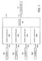
- Fig. 1 there is illustrated the principle of the operation of the present invention.
- the left-hand side of Fig. 1 shows four incoming data flows. Each data flow is associated with a queue.
- a queue is referred to herein as a context. Wherever a context is referred to, it will be understood by a skilled person that in fact the description applies to any type of queue or incoming data flow.
- a first queue (context 1) identified by reference numeral 104a is received on a signal line 106a to a scheduler 100.
- a second queue (context 2) identified by reference numeral 104b is received on an input line 106b.
- a third queue (context 3) identified by reference numeral 104c is received on an input line 106c.
- an nth queue identified by "context n" and referenced as reference numeral 104n is received on an nth input line 106n to the scheduler 100.
- each of the respective queues is associated with a queue controller.
- the queue context 1 is associated with context controller 1 102a.
- the queue context 2 is associated with a context controller 2 102b.
- the queue context 3 is associated with a context controller 3 102c.
- the queue context n is associated with a context controller n 102n.
- the scheduler 100 is provided with a scheduler controller 108 which interfaces with all of the context controllers 102a-102n.
- the scheduler 100 is further provided with a single output 110 which forms an output flow 112.
- the purpose of the scheduler is to control each of the input queues on the inputs 106a-106n such that they are presented on the single output 110.
- the implementation of the scheduling in accordance with the preferred embodiments of the present invention is described in further detail hereinafter.
- FIG. 2 illustrates in detail an example implementation of a context controller, such as context controller n 102n of Fig. 1.
- Fig. 2 also illustrates in detail an example implementation of the scheduler controller 108 of Fig. 1.
- each of the context controllers 102a-102n is constructed similarly to the context controller 102n.
- each of the context controllers 102a-102n interfaces with a scheduler controller 108 in a similar manner to that described in relation to the context controller n 102n in Fig. 2.
- the context controller n 102n includes a context control block 200, a first storage block 202, a second storage block 204, comparators 220 and 226, an incrementor 224, an adder 218 and a multiplexer 222.
- the context control block 200 generally controls the context controller 102n, using internal control signals 201. Thus all of the blocks illustrated in the block 102n in Fig. 2 will be operated under the control of the context control block 200.
- the storage means 202 includes a set of storage locations which relate to parameters fixed for the current context.
- the storage means 202 includes a store 206 for storing a priority level associated with the context, a store 208 for storing a primary context quantum associated with the context, a store 210 for storing a maximum deficit associated with the context, a store 212 for storing a maximum secondary addition associated with the context, a store 211 for storing a secondary context quantum and a store 213 for storing a minimum deficit value.
- the storage means 204 stores parameters associated with the context which may change as the context is processed by the scheduler.
- the storage means 204 includes a storage location 214 for a flow level or deficit level, and a storage location 216 for a secondary addition counter.
- the adder 218 receives as its two inputs the values stored in the primary context quantum 208 and the deficit level 214.
- the comparator 220 receives as its inputs the value stored in the maximum deficit store 210 and the output of the adder 218.
- the multiplexer 222 receives as its inputs the value stored in the maximum deficit store 210 and the output of the adder 218.
- the multiplexer 222 is controlled by the output of the comparator 220 to output one of its inputs on its output line, which forms an input to the deficit level 214 to update the value stored therein.
- the increment block 224 receives as its input the secondary addition counter value 216, and provides its output to the secondary addition counter value 216.
- the comparator 226 receives as its inputs the secondary addition counter value 216 and the maximum secondary additions value 212, and the comparator 226 forms an input to the context control block 200, on a control line 201a.
- the scheduler controller 108 in accordance with a preferred embodiment includes a scheduler control block 230, a current maximum priority storage location 232, a selected context storage location 239, a multiplexer 234, a comparator 236, and a comparator 238.
- the scheduler control block 230 generally controls the scheduler controller 108.
- Control lines 229 interface the scheduler control block to various elements of the scheduler controller 108. Thus all blocks of the scheduler controller 108 operate under the control of the scheduler control block 230.
- the comparator 236 receives as its inputs the priority level in storage location 206 of the context controller 102n and the current maximum priority in storage location 232.
- the multiplexer 234 similarly receives as its inputs the priority level in storage location 206 and the current maximum priority in storage location 232.
- the multiplexer 234 is controlled by the output of the comparator 236 to provide one of its two inputs as its output, which provides an updated value to the current maximum priority in storage location 232.
- the comparator 238 receives as an input the deficit level value in storage location 214 of the context controller 102n. The comparator 238 simply operates to compare this value to zero.
- FIG. 6 An important principle of the present invention is that the data flow from each queue, in terms of transmitted bits, is tracked. That is, a flow value for each queue is stored and maintained.
- each of the context controllers 102 is provided with a deficit level in a storage location 214.
- the deficit level is an important part for implementing the present invention.
- Fig. 6 illustrates the principle of operation of the deficit level.
- reference numeral 600 generally refers to a "bucket" into which "bit quantums" are added. As discussed further hereinbelow, the content of the bucket represents the deficit level in the storage location 214.
- Each bucket 600 has a "zero" level 606 at which a deficit level in the bucket is zero.
- the deficit level may vary above and below zero. If the deficit level varies above zero, then the queue or context associated with the bucket 600 has a lag compared to the guaranteed bit rate. In Fig. 6, a deficit level is shown at a level 604 above the zero level 606, and therefore 602 represents a lag of capacity over the guaranteed bit rate. If the deficit level is below the zero level, then the queue or context associated with the bucket 600 has a lead compared to the guaranteed bit rate.
- the deficit level has a maximum value 620, and a minimum value 622.
- a positive deficit level means that the flow has capacity lag, i.e. it needs more capacity in order to obtain the guaranteed bit rate.
- a negative deficit level indicates that the flow is satisfied.
- a positive deficit level i.e. between the zero level 606 and the maximum level 620, indicates that the queue associated with the bucket 600 should be given more transmission turns in order to obtain the guaranteed bit rate. If the queue is empty, no transmission turns are granted to the queue.
- the scheduler 100 shares the capacity of the output with that queue.
- queues having the highest priority are scheduled first, followed by lower priority queues in the priority order.
- the guaranteed throughput for each queue is controlled by the quantum parameter, denoted by Q 1 .
- the quantum parameter for each queue represents the number of bits added to the bucket 600 in an initialisation step as discussed further hereinbelow.
- the implementation is an EGPRS implementation, and that in a 20 millisecond transmission period n bits 616a-616n are added to the bucket, the n bits comprising the quantum value Q 1 .
- the quantum value is added to the bucket for each queue in a primary addition algorithm executed at the beginning of a transmission scheduling cycle.
- the maximum deficit parameter, 620 indicates the maximum throughput lag, measured in bits. As such, the maximum deficit also defines the maximum throughput compensation time that one queue can achieve.
- the minimum deficit value parameter 622 defines the maximum throughput lead for the queue and is measured in bits. This parameter defines how much capacity one context can borrow from the future.
- the maximum deficit value is stored in the storage location 210 in the context controller 102 associated with that queue. Similarly the minimum deficit value may be stored in a similar storage location.
- the context quantum Q 1 for a queue is stored in the context quantum storage location 208.
- a secondary quantum parameter, Q 2 is used as described further hereinbelow when all the queues have achieved their guaranteed throughput. Residual capacity is then distributed with proportions defined by the secondary quantum values. This parameter is used in a secondary deficit update algorithm as described in further detail hereinbelow.
- a maximum secondary additions parameter, M 2 is also defined together with the secondary quantum Q 2 .
- the maximum secondary additions parameter defines the absolute maximum throughput that one context can use in one transmission, independently of its time slot allocation.
- the maximum secondary additions parameter is stored in a storage location 212 of the context controller.
- each context or queue is associated with a priority level.
- the priority level defines the internal handling priority.
- higher priority queues or contexts are always serviced before lower priority ones. That is, scheduling is done in a strict priority order between the priority bounds.
- the main contribution of the priority parameter is notable in frame delays, such that frames in higher priority contexts experience lower delays.
- the priority for a particular queue is stored as the priority level in a storage location 206 of the context controller.
- variable parameter values must be maintained in the storage means 204.
- the deficit level is stored in storage location 214, indicating the capacity deficit level in the bucket. The deficit value is positive when there is capacity deficit in the bucket, and vice versa.
- the number of secondary additions is stored in the storage location 216. This counts the number of secondary additions for the current scheduling round. This counter is cleared during the primary update that starts the scheduling round.
- the various parameters required for implementing the preferred embodiment of the present invention are preferably stored for the whole lifetime of a particular data queue or context. However this is likely to be an implementation issue. These parameters should ideally be transferred to a new transceiver during cell reselection, if possible. This is required if the capacity loss during cell reselection needs to be fully compensated for.
- the primary deficit update is the initial sequence of steps carried out during the operation of the scheduler 100.
- One scheduling cycle occurs for every transmission period, and the primary update takes place at the beginning of that scheduling cycle.
- the primary deficit update begins in a step 302.
- the purpose of the primary deficit update is to share capacity to queues or contexts which have data which needs to be scheduled with guaranteed throughput. In order for data in a queue to be scheduled in accordance with the present invention, it is necessary for the deficit level 214 for that queue to have a value above zero.
- the primary deficit update procedure carries out an initialisation of each queue, as discussed further hereinbelow.
- a first step the first context from the list of contexts is selected, as represented by steps 304.
- this is the context 1 of Fig. 1.
- a step 306 the deficit level 214 for the context is increased by the primary context quantum, Q 1 , 208. This operation is carried out by the adder 218 which adds the values of the storage locations 208 and 214.
- a step 308 it is then determined whether the result of this addition is greater than the maximum deficit allowable.
- the comparator 220 carries out this operation, by comparing the output of the adder 218 with the maximum deficit value stored in the location 210. If the comparator determines that the output of the adder 218 is less than the maximum deficit value 210, then it controls the multiplexer 222 to set the output of the adder 218 as the new deficit level in the storage location 214. If the comparator 220 determines that the output of the adder exceeds the maximum deficit value, then the comparator 220 controls the multiplexer 222 to load the maximum deficit value in storage location 210 into the deficit level in storage location 214.
- Step 310 represents the operation of setting the deficit level 214 to the maximum deficit value 210.
- step 312 After the setting of the deficit to the maximum value in step 310 the method proceeds to step 312. If there is no deficit overflow, the method proceeds directly to step 312 from step 308.
- step 312 the value of the secondary additions counter in location 216 is cleared and set to zero under control of the context control block 200.
- the secondary additions counter 216 is always set to zero during a primary deficit update for a particular queue.
- a step 314 the next queue or context at the input of the scheduler is processed.
- a step 316 it is determined whether another queue or context exists. If a further queue or context exists, then steps 306-312 are repeated for that queue, and for all further queues at the inputs to the scheduler. If no further context exists, or if all contexts have been processed, then the method moves to step 318, and the primary deficit update is ended.
- a primary deficit update the deficit level for all context or queues is increased by the context quantum, Q 1 , for that queue.
- the method moves on to the main scheduling cycle, as illustrated by Fig. 4.
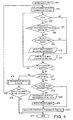
- the scheduling cycle begins in step 400, immediately after the end of the primary deficit update process.
- the first context or queue is selected. Again, for the purposes of example, it is assumed that the context 1 queue 104a is first selected.
- a first step 404 it is determined whether the packet controller unit (not shown) of which the scheduler 100 is a part has permitted the particular queue or context selected to send data. If the context or queue is not permitted to send data, then the process jumps to step 412. If the queue or context is permitted to send data, then the process proceeds to step 406.
- step 406 the priority level of the selected context or queue is compared to a previous priority level maximum.
- the scheduler controller 108 reads the priority for the current context from the priority level in storage location 206 and reads the current maximum priority from the storage location 232, and compares them in comparator 236.
- the current maximum priority 232 will be set to a predetermined value. Typically this predetermined value will represent the lowest available priority. Thus, in the present case, if it is determined that the priority of the current context is greater than the highest priority so far.
- the comparator 236 controls the multiplexer 234 to set the current maximum priority value 232 to be equal to the priority level 206. That is, the value in store 206 is carried to store 232. The process then moves on to step 408.
- the priority in storage location 206 is equal to or lower than the current maximum priority 232, then this means that there are contexts or queues at the inputs of the scheduler which have a higher priority than the current context or queue, and as such the process moves on to step 412.
- step 408 it is determined whether the deficit level for the particular context or queue in storage location 214 is greater than zero.
- the scheduler controller 108 reads the deficit level from storage location 214 and provides it as an input to comparator 238, which compares the said value with zero. If the value is greater than zero, i.e. the flow has capacity lag, then the method progresses to step 410. If the deficit is not greater than zero, i.e. the flow has capacity lead, then the process moves on to step 412.
- step 410 it has now been determined that the current context has the highest priority, and that the deficit level in storage location 214 for the current context or queue is greater than zero. As such, in step 410 this particular queue or context is selected, and the priority level in storage location 206 for this particular context or queue is copied to storage location 232 and set as the current maximum priority using the multiplexer 234.
- the scheduler control block 230 uses one of its signals 229, 229a, to enter the identification of the current context or queue into a selected context storage location 239.
- a step 412 the next context in the list is selected.
- a step 414 it is determined whether a next context actually exists. If such context exists, then the steps 404-412 are repeated for that context. If any of the next contexts have a priority level which is higher than the priority of any preceding context, then that context is selected and its identification stored in the location 239 of the scheduler controller 108. Such context or queue is only selected, however, if the deficit of such context or queue is greater than zero. Thus, the steps 404-412 are repeated for each context or queue. At the end of this sequence for each of the context or queues, the identification of the context or queue having the highest priority and having a deficit level greater than zero is stored in the storage location 239.
- step 416 it is determined whether a context has been selected. If no context has been selected, because no contexts have a deficit level greater than zero, or were not allowed to transmit, then the method proceeds to perform a secondary deficit update in a step 428.
- the secondary deficit update 428 is described further herein with reference to Fig. 5.
- step 418 it is determined if a new radio link control (RLC) block is to be transmitted.
- RLC radio link control
- the transmission of a RLC block is specific to this EGPRS embodiment. More generally, it may be considered in step 418 as to whether a block of payload data is to be transmitted. If the queue or context is about to perform a transmission of an already transmitted block, i.e. a retransmission, then the step 420 is by-passed, and the deficit level is not updated.
- step 420 If a newly generated RLC block is to be transmitted, then the deficit level in storage location 214 is decremented by the number of bits constituting the RLC block. This is represented by step 420.
- a step 422 the deficit limits are checked. That is, it is checked that the deficit level has not been decreased below the minimum deficit value, level 622 in Fig. 6. If the deficit level has been decreased below such value, then the deficit level is set at the minimum deficit value. The method then moves on to a step 424.
- step 424 the context or queue which has just been assigned a transmission turn is relocated to the end of the list of queues or contexts.
- the selected flow is always placed at the end of the flow list for the next round of scheduling. This provided round-robin scheduling within a given priority level. This round-robin functionality is especially important if the scheduler is overloaded, even for a short-time.
- a step 426 the scheduling step is terminated.
- a next primary deficit update is performed in accordance with the procedure of Fig. 3.
- a next scheduling step is performed in accordance with the above described procedure for Fig. 4.
- the scheduler 108 rotates between a primary deficit update for all queues or context, and the scheduling step for all queues or context.
- a secondary deficit update 428 is performed.
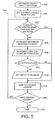
- the secondary deficit update is now described with reference to Fig. 5.
- the secondary deficit update begins in step 500.
- a step 502 the first context or queue at the input to the scheduler 100 is selected. Again, it is assumed that this is the context 1 104a.
- a first step it is determined whether the secondary update has been performed for this particular context more than the value in the maximum secondary addition storage location 212. For the first iteration, the value in the secondary additions count storage location 216 will be zero.
- the comparator 226 operates to compare the secondary additions count value in storage location 216 with the maximum secondary additions value in storage location 212, and the output of the comparator to an input on the control line 218 to the context control block 200. If the output of the comparator 226 indicates that the secondary additions count value 216 is equal to the maximum secondary additions value 212 then the secondary deficit update for the current context or queue is abandoned, and the method proceeds to step 514.
- step 306 the incrementor 224 increments the value of the secondary addition count 216 by one.
- the incrementor 224 reads in the current value of the secondary additions count and storage location 216, incremented by one, and then writes in the new value to the secondary additions count at storage location 216.
- step 508 the deficit level 214 is increased by the secondary quantum value.
- An adder receives the deficit level in storage location 214 and the secondary quantum value and provides a summed value on the output thereof.
- a step 510 it is determined whether the value at the output of the adder exceeds the maximum deficit value in storage location 210. If the maximum deficit value 210 is not exceeded, then a multiplexer is controlled by the output of the comparator to update the deficit level in storage location 214 with the output of the adder. The method then moves on to step 514.
- step 510 If in step 510 it is determined that the output of the adder does exceed the maximum deficit value 210, then the deficit level in storage location 214 is replaced with the maximum deficit value 210, by the multiplexer 222 under control of the comparator 220. Thereafter the method proceeds to step 514.
- step 514 a further context is selected.
- step 516 it is determined whether another context exists. If another context exists, then steps 504-512 are repeated for that context. If in step 516 it is determined that no further context exists, or that all contexts had been processed, then the secondary deficit update terminates in step 518. It should be noted that the secondary deficit update is only performed for those queues which have data and can transmit in the timeslot to be scheduled.
- step 430 it is determined whether any deficit was modified during the update. That is, whether any deficit count value 214 was modified during the update. If it is determined that no count values are modified during the update, then the method proceeds to step 426 and the scheduling step ends, as there is no data to transmit, or the modification of all deficit levels was prohibited by the maximum additions limits. If it is determined that any deficit level was changed, then the method returns to step 402, and the steps 404-412 are repeated for each context or queue. Once the steps 404-412 are repeated for each context or queue, it is possible that there is still no active context or queue which has a deficit greater than zero. If this is the case, then a further secondary deficit update may be performed in step 428. If a further secondary deficit update is performed, following the steps of Fig. 5, then the secondary additions count value 216 for each queue is further updated for having such further secondary deficit update.
- the method only proceeds to a primary deficit update on the beginning of a new scheduling cycle.
- the primary deficit update on a new scheduling cycle, the secondary additions counter for any queue which is processed is reset to zero.
- the present invention is thus related to scheduling. Scheduling is performed before every transmission. In EGPRS, this means that scheduling is performed once every 20ms.
- the context, or queue, list is transmission wide. That is, the context list is associated with the transmission.
- the scheduling of one transmission means that the transmitting temporary block flow is selected for each time slot.
- the scheduling starts, as discussed herein, with a primary update. This primary update is performed once, at the beginning of the transmission scheduling cycle. Thereafter, the scheduling step is performed for each time slot, one after each other.
- the scheduling step schedules eight time slots, and up to eight radio blocks may be transmitted following each scheduling cycle. That is, eight radio blocks may be transmitted between primary updates.
- the queues are transmission specific, but depending on the multi-slot allocation, the queues may only be active on selected time-slots within the transmission period. If the first iteration does not find a non-empty queue with deficit level value above zero, then a secondary update is performed on that time-slot. The secondary additions counter is cleared at the beginning of the transmission scheduling, and may be incremented on any time slot where the secondary update is performed. As any queue (temporary block flow) may be active on many time slots in the transmission, the check in step 404 of Figure 4 is performed. This check determines whether a queue (temporary block flow) can actually transmit on the time slot to be scheduled.
- a queue is selected for the output 110 of the scheduler 100 in dependence on the following rules:
- the secondary update step of Fig. 5 is performed when all data contexts in a time slot are satisfied, i.e. their guaranteed throughput requirements are fulfilled. This is performed according to the following rules:
- the maximum throughput limitation is imposed by the maximum additions parameter. It may occur that all contexts are limited by the maximum additions parameter, and then the transmission turn must be left unused, and a dummy or an idle RLC block sent in that time slot.
- the deficit levels of all contexts are updated with a primary quantum at a fixed time in the GSM time structure, using the primary deficit update algorithm as described in relation to Fig. 3.
- This primary deficit update algorithm takes place at a predetermined time.
- the predetermined time is the start of a TDMA frame.
- the new deficit level for every context is computed with the following rules:
- T M 50 * Q 1 + M ⁇ 2 * Q ⁇ 2 ⁇ bits / s
- Q 2 is the secondary quantum
- M 2 is the maximum number of secondary additions
- the allowed traffic burstiness and forced smoothing is controlled by the minimum and maximum deficit values.
- the deficit level in the "bucket" of Fig. 6 defines how much the context has used capacity above or below the allocated throughput. For example, if the context does not use all quanta collected in the bucket, the deficit value increases, and the context can use the capacity later.
- the maximum deficit value defines how much capacity the context can store for future use, or how many bits it can transmit without scheduler posed limitations, if it has allocated capacity for it.
- the minimum value defines the maximum penalty imposed on the context for the use of non-allocated capacity. If the context uses more capacity than allocated, the deficit value sinks below zero, and the context must wait for the deficit value to rise again above zero. This is only possible if the context is allowed to send even if the deficit is below zero. This situation happens only when other functions require data transmission, for example in EGPRS for polling and downlink power control.
- the minimum and maximum deficit limits essentially define the memory property of the scheduler. As such, the effect on other flows must also be considered carefully, because too high values for maximum deficit may easily break the context isolation. However, for full compensation of cell reselections, the maximum deficit should not be too low.
- the scheduler variables are transferred to the new packet control unit (PCU).
- PCU packet control unit
- the technique according to the present invention also preferably provides a fallback mechanism for overload situations.
- the deficit values for nearly all contexts are positive, and the scheduler serves the highest priority context in a round robin fashion, until their deficit values fall below zero.
- the deficit values of the high priority contexts fall below zero, the next priority context will get round-robin service.
- admission control is preferably utilised to keep the scheduler well below the overload limit.
- the preferred implementation of the present invention requires that the deficit value is updated every time when a new RLC block is generated, even when the transmission turn is forced by other blocks in the system.
- the deficit is not updated after retransmissions. This is essential for the guaranteed throughput, because retransmissions do not provide throughput from the scheduler point of view.
- the deficit value should be checked against the minimum deficit, to determine whether an underflow has happened. In that case, the deficit is set to the minimum value.
- LLC logical link control
- the present invention preferably allows even for best effort context to have reasonable resource allocation. This is feasible because the channel capacity fluctuation renders the contexts with best effort service nearly useless, if the schedule does not provide absolute minimum service for those contexts.
- the allocation for such context can be set to the minimum value that allows the upper layer protocols to work properly.
- the present invention can be preferably configured to smooth the control traffic flows. This behaviour is particularly important with the TCP/IP, which is an important upper layer protocol used with EGPRS.
- the scheduler described herein may be implemented in an appropriate network element.
- the scheduler may advantageously be implemented in a base station controller or packet controller unit, at RLC protocol level in the protocol stack.
- Corresponding scheduling takes place in the serving GPRS support node (SGSN) at a higher protocol stack layer.
- SGSN serving GPRS support node
Landscapes
- Engineering & Computer Science (AREA)
- Computer Networks & Wireless Communication (AREA)
- Signal Processing (AREA)
- Quality & Reliability (AREA)
- Data Exchanges In Wide-Area Networks (AREA)
- Mobile Radio Communication Systems (AREA)
- Circuits Of Receivers In General (AREA)
Claims (28)
- Verfahren zur Zuteilung einer Vielzahl von Eingangsströmen zu einem Ausgangsstrom, mit
Zuweisen einer Stromstufe (604) zu jedem Eingangsstrom (104), wobei die Stromstufe angibt, ob die aktuelle Zuteilung dieses Eingangsstroms zum Erfüllen eines erforderlichen Durchsatzes für diesen Eingangsstrom ausreichend ist, und Zuteilen eines Eingangsstroms, für den die jeweilige Stromstufe einen geringeren Durchsatz als den erforderlichen Durchsatz angibt,
dadurch gekennzeichnet, dass
der Schritt der Zuweisung einer Stromstufe zu jedem Eingangsstrom ein Zuweisen eines Schwellenwerts (606) für jeden Eingangsstrom umfasst, wobei der Schwellenwert derart eingestellt ist, dass die den Schwellenwert überschreitende Stromstufe angibt, dass der erforderliche Durchsatz nicht erfüllt wird. - Verfahren nach Anspruch 1, ferner mit dem Schritt der Bestimmung, ob ein Eingangsstroms (104) zu sendende Daten aufweist, und Zuteilen lediglich solcher Eingangsströme, die zu sendende Daten aufweisen.
- Verfahren nach Anspruch 1, wobei der Ausgangsstrom (112) in Zeitschlitze eingeteilt ist, wobei das Verfahren ferner umfasst
Bestimmen des Zeitschlitzes eines Eingangsstroms (104) und Zuteilen solcher Eingangsströme mit Daten, die in dem aktuellen Ausgangsstromzeitschlitz zu senden sind. - Verfahren nach Anspruch 1, wobei die Eingangsströme (104) mit einer vorbestimmten Folge verbunden sind, so dass dann, wenn mehr als ein Eingangsstrom eine jeweilige Stromstufe (606) aufweisen, die einen geringeren Durchsatz als einen erforderlichen Durchsatz angibt, jeder derartige Eingangsstrom in Folge zugeteilt wird.
- Verfahren nach Anspruch 4, wobei ein zugeteilter Eingangsstrom (104) an das Ende der Folge bewegt wird.
- Verfahren nach Anspruch 4, ferner mit dem Schritt des Zuweisens einer Priorität zu jedem Eingangsstrom (104), wobei der Schritt der Zuteilung eines Eingangsstroms ferner von der einem Eingangsstrom zugewiesenen Priorität abhängt.
- Verfahren nach Anspruch 5, ferner mit dem Schritt des Zuweisens einer Priorität zu jedem Eingangsstrom (104), wobei ein zugeteilter Eingangsstrom an das Ende der Folge von Strömen mit derselben Priorität bewegt wird.
- Verfahren nach Anspruch 6, wobei ein Eingangsstrom (104) mit der höchsten Priorität vor jedem anderen Eingangsstrom zugeteilt wird.
- Verfahren nach Anspruch 6, wobei dann, wenn mehr als ein Eingangsstrom (104) dieselbe Priorität haben, die Eingangsströme in Folge zugeteilt werden.
- Verfahren nach einem der vorgehenden Ansprüche, wobei der Schwellenwert (606) null ist.
- Verfahren nach Anspruch 1, wobei das Zuteilen in einem Anfangsschritt eine Erhöhung der Stromstufe (604) jedes Eingangsstroms um einen jeweiligen vorbestimmten Betrag umfasst.
- Verfahren nach Anspruch 1, wobei dann, wenn ein Eingangsstrom (104) eine Stromstufe (604) über ihrem Schwellenwert aufweist, die Stromstufe für jeden Eingangsstrom um einen jeweiligen vorbestimmten Betrag erhöht wird.
- Verfahren nach Anspruch 11, wobei die Stromstufe (604) für jeden Eingangsstrom (104) mit einer maximalen Stromstufe verbunden ist, wobei die Stromstufe die maximale Stromstufe nicht überschreiten darf.
- Verfahren nach Anspruch 1, ferner mit dem Schritt der Verringerung der mit einem Eingangsstrom verbundenen Stromstufe (606) im Ansprechen auf die Zuteilung dieses Eingangsstroms (104).
- Verfahren nach Anspruch 14, wobei die Stromstufe (604) um einen der Anzahl zugeteilter Bits entsprechenden Betrag verringert wird.
- Verfahren nach Anspruch 14, wobei die Stromstufe (604) für jeden Eingangsstrom (104) mit einer minimalen Stromstufe verbunden ist, wobei die Stromstufe die minimale Stromstufe nicht überschreiten darf.
- Verfahren nach einem der vorhergehenden Ansprüche, wobei die Stromstufe jedes Eingangsstroms die Anzahl an Bits angibt, die aus dem Eingangsstrom zuzuteilen sind.
- Verfahren nach Anspruch 1, wobei ein Eingangsstrom (104) ferner in Abhängigkeit davon zugeteilt wird, dass der Eingangsstrom Daten senden darf.
- Zuteilungsvorrichtung zum Zuteilen einer Vielzahl von Eingangsströmen (104) zu einem Ausgangsstrom (112), mit
einer Einrichtung zum Zuweisen einer Stromstufe (604) zu jedem Eingangsstrom, wobei die Stromstufe angibt, ob die aktuelle Zuteilung dieses Eingangsstroms zum Erfüllen eines erforderlichen Durchsatzes für diesen Eingangsstrom ausreicht, und
einer Einrichtung zum Zuteilen eines Eingangsstroms, für den die jeweilige Stromstufe einen geringeren Durchsatz als den erforderlichen Durchsatz angibt,
dadurch gekennzeichnet, dass
die Einrichtung zum Zuweisen einer Stromstufe zu jedem Eingangsstrom eine Einrichtung zum Zuweisen eines Schwellenwerts (606) für jeden Eingangsstrom umfasst, wobei der Schwellenwert derart eingestellt ist, dass dann, wenn die Stromstufe den Schwellenwert überschreitet, der erforderliche Durchsatz nicht erfüllt wird. - Zuteilungsvorrichtung nach Anspruch 19, ferner mit einer Einrichtung zur Bestimmung, ob ein Eingangsstrom (104) zu sendende Daten aufweist, wobei die Zuteilungseinrichtung zum Zuteilen lediglich solcher Eingangsströme eingerichtet ist, die zu sendende Daten aufweisen.
- Zuteilungsvorrichtung nach Anspruch 19, wobei die Eingangsströme (104) mit einer vorbestimmten Folge verbunden sind, wobei die Zuteilungseinrichtung derart eingerichtet ist, dass dann, wenn mehr als ein Eingangsstrom eine jeweilige Stromstufe (604) aufweisen, die einen geringeren Durchsatz als einen erforderlichen Durchsatz angibt, jeder derartige Eingangsstrom in Folge zugeteilt wird.
- Zuteilungsvorrichtung nach Anspruch 19, wobei ein zugeteilter Eingangsstrom (104) an das Ende der Folge bewegt wird.
- Zuteilungsvorrichtung nach Anspruch 21, wobei eine Priorität mit jedem Eingangsstrom (104) verbunden ist, wobei die Zuteilungseinrichtung zum Zuteilen eines Eingangsstroms in Abhängigkeit von der einem Eingangsstrom zugewiesenen Priorität eingerichtet ist.
- Zuteilungsvorrichtung nach Anspruch 22, ferner mit einer Einrichtung zum Zuweisen einer Priorität zu jedem Eingangsstrom (104), wobei ein zugeteilter Eingangsstrom an das Ende der Folge von Strömen mit derselben Priorität bewegt wird.
- Zuteilungsvorrichtung nach Anspruch 19, wobei die Zuteilungseinrichtung die Stromstufe (604) jedes Eingangsstroms (104) um einen jeweiligen vorbestimmten Betrag vor der Zuteilung erhöht.
- Zuteilungsvorrichtung nach Anspruch 19, ferner mit einer Einrichtung zum Erhöhen der Stromstufe (604) für jeden Eingangsstrom (104) um einen zweiten vorbestimmten Betrag, wenn die Stromstufe aller Eingangsströme angibt, dass der aktuelle Durchsatz höher als der erforderliche garantierte Durchsatz für den jeweiligen Eingangsstrom ist.
- Zuteilungsvorrichtung nach Anspruch 19, ferner mit einer Einrichtung zum Verringern der mit einem Eingangsstrom verbundenen Stromstufe (604) im Ansprechen auf die Zuteilung dieses Eingangsstroms (104).
- Zuteilungsvorrichtung nach einem der Ansprüche 19 bis 27, wobei die Stromstufe (604) für jeden Eingangsstrom (104) die Anzahl von Bits angibt, die von dem Eingangsstrom zuzuteilen sind, und die Zuteilungsvorrichtung eine Einrichtung zum Verringern der Stromstufe für einen Eingangsstrom um einen der Anzahl zugeteilter Bits entsprechenden Betrag umfasst, wenn diese Stromstufe über ihrem jeweiligen Schwellenwert (606) liegt.
Applications Claiming Priority (3)
| Application Number | Priority Date | Filing Date | Title |
|---|---|---|---|
| US10/322,789 US20040120258A1 (en) | 2002-12-19 | 2002-12-19 | Traffic channel scheduling |
| US322789 | 2002-12-19 | ||
| PCT/IB2003/005800 WO2004057811A1 (en) | 2002-12-19 | 2003-12-04 | Traffic channel scheduling |
Publications (2)
| Publication Number | Publication Date |
|---|---|
| EP1573980A1 EP1573980A1 (de) | 2005-09-14 |
| EP1573980B1 true EP1573980B1 (de) | 2007-02-07 |
Family
ID=32593032
Family Applications (1)
| Application Number | Title | Priority Date | Filing Date |
|---|---|---|---|
| EP03777051A Expired - Lifetime EP1573980B1 (de) | 2002-12-19 | 2003-12-04 | Verkehrskanalszuteilung |
Country Status (7)
| Country | Link |
|---|---|
| US (1) | US20040120258A1 (de) |
| EP (1) | EP1573980B1 (de) |
| AT (1) | ATE353510T1 (de) |
| AU (1) | AU2003286308A1 (de) |
| DE (1) | DE60311679T2 (de) |
| ES (1) | ES2280818T3 (de) |
| WO (1) | WO2004057811A1 (de) |
Families Citing this family (10)
| Publication number | Priority date | Publication date | Assignee | Title |
|---|---|---|---|---|
| KR100514190B1 (ko) * | 2003-01-03 | 2005-09-13 | 삼성전자주식회사 | 무선 랜망에서 무선 아이피 단말에 대한 에이피의 무선채널 운용방법 |
| US7430207B2 (en) * | 2005-02-07 | 2008-09-30 | Reti Corporation | Preemptive weighted round robin scheduler |
| US20060291395A1 (en) * | 2005-06-28 | 2006-12-28 | Nokia Corporation | Packet transmission control method and apparatus |
| KR100745679B1 (ko) * | 2005-12-08 | 2007-08-02 | 한국전자통신연구원 | 적응 라운드 로빈을 이용한 패킷 스케쥴링 방법 및 장치 |
| US9179366B2 (en) * | 2006-08-31 | 2015-11-03 | Intel Corporation | Scheduling methods and apparatus based on adjusted channel capacity |
| GB0619519D0 (en) * | 2006-10-04 | 2006-11-15 | Siemens Ag | Packet scheduling |
| WO2014137253A1 (en) * | 2013-03-04 | 2014-09-12 | Telefonaktiebolaget L M Ericsson (Publ) | Method for allocating frame transmission time slots |
| CN106656858B (zh) * | 2016-08-10 | 2019-10-29 | 广州市香港科大霍英东研究院 | 基于同向流的调度方法和服务器 |
| JP6889126B2 (ja) * | 2018-03-20 | 2021-06-18 | 株式会社東芝 | 転送制御装置、転送制御方法及びプログラム |
| WO2021181137A1 (en) * | 2020-03-12 | 2021-09-16 | Telefonaktiebolaget Lm Ericsson (Publ) | Dynamic machine learning decision threshold for resource allocation |
Family Cites Families (8)
| Publication number | Priority date | Publication date | Assignee | Title |
|---|---|---|---|---|
| US6714517B1 (en) * | 1998-11-10 | 2004-03-30 | Extreme Networks | Method and apparatus for interconnection of packet switches with guaranteed bandwidth |
| US6229795B1 (en) * | 1999-01-13 | 2001-05-08 | Qualcomm Incorporated | System for allocating resources in a communication system |
| US6570883B1 (en) * | 1999-08-28 | 2003-05-27 | Hsiao-Tung Wong | Packet scheduling using dual weight single priority queue |
| AU2001236303A1 (en) * | 2000-02-25 | 2001-09-03 | Telefonaktiebolaget Lm Ericsson (Publ) | Flow control between transmitter and receiver entities in a communications system |
| US6914881B1 (en) * | 2000-11-28 | 2005-07-05 | Nortel Networks Ltd | Prioritized continuous-deficit round robin scheduling |
| US7236491B2 (en) * | 2000-11-30 | 2007-06-26 | Industrial Technology Research Institute | Method and apparatus for scheduling for packet-switched networks |
| US6917591B2 (en) * | 2001-01-12 | 2005-07-12 | Telefonaktiebolaget Lm Ericsson (Publ) | Methods, systems and computer program products for bandwidth allocation in a multiple access system |
| US7177275B2 (en) * | 2002-07-26 | 2007-02-13 | Kenneth Stanwood | Scheduling method and system for communication systems that offer multiple classes of service |
-
2002
- 2002-12-19 US US10/322,789 patent/US20040120258A1/en not_active Abandoned
-
2003
- 2003-12-04 AU AU2003286308A patent/AU2003286308A1/en not_active Abandoned
- 2003-12-04 EP EP03777051A patent/EP1573980B1/de not_active Expired - Lifetime
- 2003-12-04 DE DE60311679T patent/DE60311679T2/de not_active Expired - Fee Related
- 2003-12-04 AT AT03777051T patent/ATE353510T1/de not_active IP Right Cessation
- 2003-12-04 ES ES03777051T patent/ES2280818T3/es not_active Expired - Lifetime
- 2003-12-04 WO PCT/IB2003/005800 patent/WO2004057811A1/en not_active Ceased
Also Published As
| Publication number | Publication date |
|---|---|
| WO2004057811A1 (en) | 2004-07-08 |
| DE60311679D1 (de) | 2007-03-22 |
| ES2280818T3 (es) | 2007-09-16 |
| ATE353510T1 (de) | 2007-02-15 |
| AU2003286308A1 (en) | 2004-07-14 |
| EP1573980A1 (de) | 2005-09-14 |
| US20040120258A1 (en) | 2004-06-24 |
| DE60311679T2 (de) | 2007-10-25 |
Similar Documents
| Publication | Publication Date | Title |
|---|---|---|
| EP2283620B1 (de) | Partitionierungsentität und verfahren zur kapazitätspartitionierung | |
| USRE43593E1 (en) | Base station, radio resource control equipment, mobile station, communication system, and communication method | |
| US6996061B2 (en) | Dynamic scheduling for packet data network | |
| EP2005669B1 (de) | Priorisierung der datenübertragung | |
| US8767553B2 (en) | Dynamic resource partitioning for long-term fairness to non-elastic traffic on a cellular basestation | |
| US20180014221A1 (en) | Fair Distribution Of Radio Resources Between Guaranteed Bit Rate (GBR) And Non-GBR Data Bearers | |
| EP1839414B1 (de) | Berechtigungsanfrage von einer basisstation zum senden von sich in einer warteschlange befindlichen paketen in einem mobilen endgerät gemäss ihrer übertragungsverzögerung | |
| US7257083B2 (en) | Method and apparatus for policy-based dynamic preemptive scheduling of data transmissions | |
| EP2235994B1 (de) | Verfahren und anordnung in einem telekommunikationssystem | |
| US20010024452A1 (en) | Data rate limiting | |
| EP1364496A1 (de) | Dynamische bandbreitenzuteilung | |
| CN101621457A (zh) | 一种多业务调度方法和系统 | |
| US9788210B2 (en) | Methods and systems for adaptive buffer allocations in systems with adaptive resource allocation | |
| US7193992B2 (en) | Method of radio resource management for integrated voice and data CDMA networks | |
| EP3338499B1 (de) | Verminderung von freiem datenverkehr in der uplink-planung | |
| US20030185214A1 (en) | System and method for scheduling protocol data units | |
| JP4981139B2 (ja) | パケットスケジューリング | |
| US7843825B2 (en) | Method and system for packet rate shaping | |
| US20040120258A1 (en) | Traffic channel scheduling | |
| KR101512993B1 (ko) | 통신을 위한 방법 및 그를 위한 라디오 스테이션 | |
| EP2556714B1 (de) | Verfahren und Knoten zur Handhabung von Warteschlangen in Kommunikationsnetzen und entsprechendes Computerprogrammprodukt | |
| EP1832015B1 (de) | Verfahren zur zeitplanung von ressourcen auf paketebene für integrierte ebenen für integrierten verkehr sowie vorrichtung dafür | |
| EP1817878B1 (de) | Airtimegerechte übertragungsregulierung ohne explizite verkehrsspezifikationen für drahtlose netzwerke | |
| EP1244318B1 (de) | Adaptives Verfahren zur Schwellwertbestimmung für den verschiedenartigen Zugriff auf Netzressourcen | |
| EP2057797B1 (de) | Ablaufplanungsverfahren und vorrichtungen auf der basis einer justierten kanalkapazität |
Legal Events
| Date | Code | Title | Description |
|---|---|---|---|
| PUAI | Public reference made under article 153(3) epc to a published international application that has entered the european phase |
Free format text: ORIGINAL CODE: 0009012 |
|
| 17P | Request for examination filed |
Effective date: 20050617 |
|
| AK | Designated contracting states |
Kind code of ref document: A1 Designated state(s): AT BE BG CH CY CZ DE DK EE ES FI FR GB GR HU IE IT LI LU MC NL PT RO SE SI SK TR |
|
| AX | Request for extension of the european patent |
Extension state: AL LT LV MK |
|
| DAX | Request for extension of the european patent (deleted) | ||
| GRAP | Despatch of communication of intention to grant a patent |
Free format text: ORIGINAL CODE: EPIDOSNIGR1 |
|
| GRAS | Grant fee paid |
Free format text: ORIGINAL CODE: EPIDOSNIGR3 |
|
| GRAA | (expected) grant |
Free format text: ORIGINAL CODE: 0009210 |
|
| AK | Designated contracting states |
Kind code of ref document: B1 Designated state(s): AT BE BG CH CY CZ DE DK EE ES FI FR GB GR HU IE IT LI LU MC NL PT RO SE SI SK TR |
|
| PG25 | Lapsed in a contracting state [announced via postgrant information from national office to epo] |
Ref country code: BE Free format text: LAPSE BECAUSE OF FAILURE TO SUBMIT A TRANSLATION OF THE DESCRIPTION OR TO PAY THE FEE WITHIN THE PRESCRIBED TIME-LIMIT Effective date: 20070207 Ref country code: LI Free format text: LAPSE BECAUSE OF FAILURE TO SUBMIT A TRANSLATION OF THE DESCRIPTION OR TO PAY THE FEE WITHIN THE PRESCRIBED TIME-LIMIT Effective date: 20070207 Ref country code: AT Free format text: LAPSE BECAUSE OF FAILURE TO SUBMIT A TRANSLATION OF THE DESCRIPTION OR TO PAY THE FEE WITHIN THE PRESCRIBED TIME-LIMIT Effective date: 20070207 Ref country code: SI Free format text: LAPSE BECAUSE OF FAILURE TO SUBMIT A TRANSLATION OF THE DESCRIPTION OR TO PAY THE FEE WITHIN THE PRESCRIBED TIME-LIMIT Effective date: 20070207 Ref country code: CH Free format text: LAPSE BECAUSE OF FAILURE TO SUBMIT A TRANSLATION OF THE DESCRIPTION OR TO PAY THE FEE WITHIN THE PRESCRIBED TIME-LIMIT Effective date: 20070207 Ref country code: FI Free format text: LAPSE BECAUSE OF FAILURE TO SUBMIT A TRANSLATION OF THE DESCRIPTION OR TO PAY THE FEE WITHIN THE PRESCRIBED TIME-LIMIT Effective date: 20070207 Ref country code: DK Free format text: LAPSE BECAUSE OF FAILURE TO SUBMIT A TRANSLATION OF THE DESCRIPTION OR TO PAY THE FEE WITHIN THE PRESCRIBED TIME-LIMIT Effective date: 20070207 Ref country code: NL Free format text: LAPSE BECAUSE OF FAILURE TO SUBMIT A TRANSLATION OF THE DESCRIPTION OR TO PAY THE FEE WITHIN THE PRESCRIBED TIME-LIMIT Effective date: 20070207 |
|
| REG | Reference to a national code |
Ref country code: GB Ref legal event code: FG4D |
|
| REG | Reference to a national code |
Ref country code: CH Ref legal event code: EP |
|
| REG | Reference to a national code |
Ref country code: IE Ref legal event code: FG4D |
|
| REF | Corresponds to: |
Ref document number: 60311679 Country of ref document: DE Date of ref document: 20070322 Kind code of ref document: P |
|
| PG25 | Lapsed in a contracting state [announced via postgrant information from national office to epo] |
Ref country code: SE Free format text: LAPSE BECAUSE OF FAILURE TO SUBMIT A TRANSLATION OF THE DESCRIPTION OR TO PAY THE FEE WITHIN THE PRESCRIBED TIME-LIMIT Effective date: 20070507 |
|
| PG25 | Lapsed in a contracting state [announced via postgrant information from national office to epo] |
Ref country code: BG Free format text: LAPSE BECAUSE OF EXPIRATION OF PROTECTION Effective date: 20070508 |
|
| PG25 | Lapsed in a contracting state [announced via postgrant information from national office to epo] |
Ref country code: PT Free format text: LAPSE BECAUSE OF FAILURE TO SUBMIT A TRANSLATION OF THE DESCRIPTION OR TO PAY THE FEE WITHIN THE PRESCRIBED TIME-LIMIT Effective date: 20070709 |
|
| ET | Fr: translation filed | ||
| NLV1 | Nl: lapsed or annulled due to failure to fulfill the requirements of art. 29p and 29m of the patents act | ||
| REG | Reference to a national code |
Ref country code: CH Ref legal event code: PL |
|
| REG | Reference to a national code |
Ref country code: ES Ref legal event code: FG2A Ref document number: 2280818 Country of ref document: ES Kind code of ref document: T3 |
|
| PG25 | Lapsed in a contracting state [announced via postgrant information from national office to epo] |
Ref country code: SK Free format text: LAPSE BECAUSE OF FAILURE TO SUBMIT A TRANSLATION OF THE DESCRIPTION OR TO PAY THE FEE WITHIN THE PRESCRIBED TIME-LIMIT Effective date: 20070207 |
|
| PLBE | No opposition filed within time limit |
Free format text: ORIGINAL CODE: 0009261 |
|
| STAA | Information on the status of an ep patent application or granted ep patent |
Free format text: STATUS: NO OPPOSITION FILED WITHIN TIME LIMIT |
|
| PG25 | Lapsed in a contracting state [announced via postgrant information from national office to epo] |
Ref country code: CZ Free format text: LAPSE BECAUSE OF FAILURE TO SUBMIT A TRANSLATION OF THE DESCRIPTION OR TO PAY THE FEE WITHIN THE PRESCRIBED TIME-LIMIT Effective date: 20070207 Ref country code: RO Free format text: LAPSE BECAUSE OF FAILURE TO SUBMIT A TRANSLATION OF THE DESCRIPTION OR TO PAY THE FEE WITHIN THE PRESCRIBED TIME-LIMIT Effective date: 20070207 |
|
| 26N | No opposition filed |
Effective date: 20071108 |
|
| PGFP | Annual fee paid to national office [announced via postgrant information from national office to epo] |
Ref country code: IT Payment date: 20071219 Year of fee payment: 5 |
|
| PG25 | Lapsed in a contracting state [announced via postgrant information from national office to epo] |
Ref country code: GR Free format text: LAPSE BECAUSE OF FAILURE TO SUBMIT A TRANSLATION OF THE DESCRIPTION OR TO PAY THE FEE WITHIN THE PRESCRIBED TIME-LIMIT Effective date: 20070508 |
|
| PGFP | Annual fee paid to national office [announced via postgrant information from national office to epo] |
Ref country code: ES Payment date: 20071228 Year of fee payment: 5 Ref country code: GB Payment date: 20071218 Year of fee payment: 5 |
|
| PGFP | Annual fee paid to national office [announced via postgrant information from national office to epo] |
Ref country code: DE Payment date: 20071221 Year of fee payment: 5 |
|
| PG25 | Lapsed in a contracting state [announced via postgrant information from national office to epo] |
Ref country code: MC Free format text: LAPSE BECAUSE OF NON-PAYMENT OF DUE FEES Effective date: 20071231 |
|
| PGFP | Annual fee paid to national office [announced via postgrant information from national office to epo] |
Ref country code: FR Payment date: 20071217 Year of fee payment: 5 |
|
| PG25 | Lapsed in a contracting state [announced via postgrant information from national office to epo] |
Ref country code: IE Free format text: LAPSE BECAUSE OF NON-PAYMENT OF DUE FEES Effective date: 20071204 |
|
| PG25 | Lapsed in a contracting state [announced via postgrant information from national office to epo] |
Ref country code: EE Free format text: LAPSE BECAUSE OF FAILURE TO SUBMIT A TRANSLATION OF THE DESCRIPTION OR TO PAY THE FEE WITHIN THE PRESCRIBED TIME-LIMIT Effective date: 20070207 |
|
| PG25 | Lapsed in a contracting state [announced via postgrant information from national office to epo] |
Ref country code: CY Free format text: LAPSE BECAUSE OF FAILURE TO SUBMIT A TRANSLATION OF THE DESCRIPTION OR TO PAY THE FEE WITHIN THE PRESCRIBED TIME-LIMIT Effective date: 20070207 |
|
| GBPC | Gb: european patent ceased through non-payment of renewal fee |
Effective date: 20081204 |
|
| PG25 | Lapsed in a contracting state [announced via postgrant information from national office to epo] |
Ref country code: LU Free format text: LAPSE BECAUSE OF NON-PAYMENT OF DUE FEES Effective date: 20071204 |
|
| PG25 | Lapsed in a contracting state [announced via postgrant information from national office to epo] |
Ref country code: TR Free format text: LAPSE BECAUSE OF FAILURE TO SUBMIT A TRANSLATION OF THE DESCRIPTION OR TO PAY THE FEE WITHIN THE PRESCRIBED TIME-LIMIT Effective date: 20070207 Ref country code: HU Free format text: LAPSE BECAUSE OF FAILURE TO SUBMIT A TRANSLATION OF THE DESCRIPTION OR TO PAY THE FEE WITHIN THE PRESCRIBED TIME-LIMIT Effective date: 20070808 |
|
| REG | Reference to a national code |
Ref country code: FR Ref legal event code: ST Effective date: 20090831 |
|
| PG25 | Lapsed in a contracting state [announced via postgrant information from national office to epo] |
Ref country code: DE Free format text: LAPSE BECAUSE OF NON-PAYMENT OF DUE FEES Effective date: 20090701 |
|
| PG25 | Lapsed in a contracting state [announced via postgrant information from national office to epo] |
Ref country code: GB Free format text: LAPSE BECAUSE OF NON-PAYMENT OF DUE FEES Effective date: 20081204 |
|
| REG | Reference to a national code |
Ref country code: ES Ref legal event code: FD2A Effective date: 20081205 |
|
| PG25 | Lapsed in a contracting state [announced via postgrant information from national office to epo] |
Ref country code: FR Free format text: LAPSE BECAUSE OF NON-PAYMENT OF DUE FEES Effective date: 20081231 Ref country code: ES Free format text: LAPSE BECAUSE OF NON-PAYMENT OF DUE FEES Effective date: 20081205 |
|
| PG25 | Lapsed in a contracting state [announced via postgrant information from national office to epo] |
Ref country code: IT Free format text: LAPSE BECAUSE OF NON-PAYMENT OF DUE FEES Effective date: 20081204 |