EP1574335A1 - Dispositif pour amener des objets vers- et pour les enlever d'une machine à décorer - Google Patents
Dispositif pour amener des objets vers- et pour les enlever d'une machine à décorer Download PDFInfo
- Publication number
- EP1574335A1 EP1574335A1 EP04026762A EP04026762A EP1574335A1 EP 1574335 A1 EP1574335 A1 EP 1574335A1 EP 04026762 A EP04026762 A EP 04026762A EP 04026762 A EP04026762 A EP 04026762A EP 1574335 A1 EP1574335 A1 EP 1574335A1
- Authority
- EP
- European Patent Office
- Prior art keywords
- transport
- station
- suction head
- objects
- belt
- Prior art date
- Legal status (The legal status is an assumption and is not a legal conclusion. Google has not performed a legal analysis and makes no representation as to the accuracy of the status listed.)
- Withdrawn
Links
Images



Classifications
-
- B—PERFORMING OPERATIONS; TRANSPORTING
- B41—PRINTING; LINING MACHINES; TYPEWRITERS; STAMPS
- B41F—PRINTING MACHINES OR PRESSES
- B41F17/00—Printing apparatus or machines of special types or for particular purposes, not otherwise provided for
- B41F17/08—Printing apparatus or machines of special types or for particular purposes, not otherwise provided for for printing on filamentary or elongated articles, or on articles with cylindrical surfaces
- B41F17/14—Printing apparatus or machines of special types or for particular purposes, not otherwise provided for for printing on filamentary or elongated articles, or on articles with cylindrical surfaces on articles of finite length
- B41F17/16—Printing apparatus or machines of special types or for particular purposes, not otherwise provided for for printing on filamentary or elongated articles, or on articles with cylindrical surfaces on articles of finite length on end or bottom surfaces thereof
-
- B—PERFORMING OPERATIONS; TRANSPORTING
- B41—PRINTING; LINING MACHINES; TYPEWRITERS; STAMPS
- B41P—INDEXING SCHEME RELATING TO PRINTING, LINING MACHINES, TYPEWRITERS, AND TO STAMPS
- B41P2217/00—Printing machines of special types or for particular purposes
- B41P2217/50—Printing presses for particular purposes
- B41P2217/55—Printing presses for particular purposes for printing compact discs
Definitions
- the invention relates to a device for feeding and carrying away of objects according to the preamble of claim 1.
- Such a device is known from US 6,082,256 which discloses a device for printing CDs.
- the to be printed CDs are stacked in magazines in a separating station brought, in which there each located Magazine is emptied, at the same time the CDs singled become.
- the individual CDs are consecutively to the recording station transported in which they are in the slides are inserted, which the objects along a transport path through the individual treatment stations of the printing machine transport.
- the printed objects are in one in the Transport path of the printing press provided removal station taken from the slides and towards a collecting station transported, in which the individual objects then be stacked again in a magazine arranged there.
- the throughput of the whole machine is also determined by the throughput of the facilities that are needed to separate the objects to be printed and the printing press feed as well as the printed objects again from the Lead away and collect printing press.
- the type considered here is a constellation possible, in which the maximum throughput of the actual printing press can not be used because of that Separating and feeding the objects to be printed to the printing press and removing from the printing machine of the printed Objects and collecting them with a throughput take place, which are below that of the actual printing press can.
- the invention is based on the object, a device to modify the type described in the introduction so that the maximum throughput of the device a noticeable Improvement experiences.
- the aim is to Time, which is related to the handling of objects the singling and the subsequent transport of the same to Printing machine is required to decrease. The same also applies to the handling of the printed objects that the Machine are removed and fed to a collection station need to be stacked in a magazine again.
- transport belts and the consequent linear transport of the individual objects Clarity and accessibility of the device at.
- the use of transport belts also has the advantage that the respective length of the same more or less freely selectable is. There is thus the possibility along the transport route the belt provide additional stations in which For example, objects depending on the result of any Tests, for example, the print quality, from the Handling system are led out.
- suction cups connected to a vacuum source can be connected and record the respective object, during transport and other handling and then release it again.
- suction cups for These purposes are well known, such as, for example U.S. Patent 5,520,107.
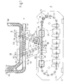
- the embodiment shown in the drawing comprises an area A, which has the actual printing machine 10, and an area B containing the facilities for the Transport of the objects to be printed to the printing press and for the removal of the printed objects from the press to downstream facilities, so the handling system has (Fig. 1).
- the printing machine 10 is used for printing flat objects, For example, CDs, credit cards or the like. It has several as carriages trained slides 14, each of which on the upper side is provided with a receptacle 16 for an object 15.
- the slides 14 are in the direction of arrow 17 along an endless transport path 18 moves, consisting of two in one horizontally spaced linear sections 20, 21 and two approximately semi-circular sections 23, 24, the two linear sections 20, 21 with each other connect.
- Each of the two linear sections 20, 21 the transport path 18 is not shown in the drawing Transport screw associated with the transport of the slide 14 in the linear sections 20, 21 causes.
- Each the two semicircular portions 23, 24 is one each circulating in a horizontal plane, only indicated in the drawing Assigned drive wheel 25, the continuous or can circulate discontinuously.
- a possible design Such a machine is described in U.S. Patent 6,082,256 and shown. The disclosure of this PS is in the Disclosure of this application.
- a separating station 36, 37 (FIGS. 2 and 5) are provided, in each of which a magazine can be positioned, which provided with a stack of CDs to be printed.
- the jointly movable up and down gripper parts 39a, b adapted to the shape and dimensions of the magazine foot 33 are and in their closed position the above, top Edge 40 of the foot 33 engage under the magazine by a movable stop, not shown, the tight is provided above the respective conveyor belt 29, 30, has been stopped.
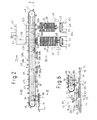
- the gripper device becomes, after they has been closed and has grasped the foot 33, raised, so that the magazine is no longer in contact with the general continuously circulating respective conveyor belt 29 and 30, respectively, and the CD stack in the magazine one above the magazine at a distance from the respective conveyor belt 29 and 30 arranged lifting part 42a or 42b of a lifting or acceptance device 42 aligned is; the end of the printing machine 10 facing away from a first formed as a transport bar transport device 43 is provided (Fig. 2).
- the latter extends between the two separation stations 36, 37 on the one hand and a Turntable 44 on the other hand, which with four receptacles for the provided each object 15 and a short distance from the positioned nearest linear section 20 of the transport path 18 is (FIG. 6).
- the transport bar is provided with a support 46, which serves to support a circulating in the vertical plane conveyor belt, which is designed as a toothed belt 47.
- a drive or reverse roller 48, 49 is attached, over which the toothed belt 47 is guided.
- FIGS. 2-4 show that the lower section 47a of the toothed belt 47 closes a longitudinal groove-shaped recess 51 provided on the underside of the carrier 46, which is connected to a vacuum source.
- a strip-shaped seal 53 is arranged at its lower boundary surface adjacent to the edge regions of the lower section 47a of the toothed belt, which engages under the respective edge region.
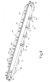
- the groove-shaped recess 51 is connected via a plurality of connecting channels 54 with a vacuum line 56 extending along the carrier 46 of the transport bar 43, which can be seen in FIG. 8, which shows a second transport device 90 designed as a transport bar.
- suction heads are mounted along its longitudinal course such that they move away from the carrier 46 and thus in the lower portion 47a down and in the upper portion 47b extend upwards.
- These suction cups 58a, 58b are in pairs arranged such that the distance between two suction head pairs smaller than the diameter of the transportable Object.
- holes 50 are mounted with the the respective suction head 58a, b are substantially aligned and the Connection between the negative pressure recess 51 on the one hand and the respective suction head on the other hand, which protrudes relative to the toothed belt 47 and at its the toothed belt turned away end is open.
- the timing belt is running in the direction of the arrow 61, so that in the separating stations 36, 37 each recorded CDs through the section 47a in a manner to be described to the turntable 44th be transported.
- the two jointly actuated lifting parts 42a, 42b of the on and movable on the transport bar mounted lifting device Each have substantially the shape of a downwardly open U frame on and are arranged such that the transport bar with the timing belt 47 between the two Legs 63a and 63b of the respective U-frame extends, so that the U-frame overlaps the transport bar with toothed belt 47.
- the distance between the two lifting parts 42a, 42b in The longitudinal direction of the transport bar corresponds to the length of one Transport step of the toothed belt 47 and the distance between the two separation stations 36, 37, along the Course of the transport bar are arranged one behind the other.
- Each of the two legs 63a, 63b of each U-shaped frame is at its lower end with a suction head pair 65a, 65b provided in a suitable manner to the already existing vacuum source is connectable. Every suction head is - like also all other suction heads - as a short bellows section educated.
- the magazines located in the separating stations 36, 37 are emptied alternately by the in the respective magazine CDs are successively removed from the stack.
- a usual Lifting arm 45 raised so that the uppermost lying CD of the stack is at a height below the respective lifting part the take-off device 42 is located, in which the suction head pairs 65a, 65b of this lifting part in the lower layer thereof come in contact with the top surface of this CD.
- the Lifting arm 45 is engaged with a sleeve 95, which is displaceable sitting on the mandrel 34 of the magazine 32 and the CD stack wearing.
- the lift arm also has the function in a known manner, after removing the topmost CD to move the stack up the thickness of a CD, so to bring the following CD into the position in which they are absorbed by the suction head pairs 65a, 65b of the lifting part can be.
- the removal of the CDs from the respective stack is running so from that to empty the z. B. in the separation station 36 located the main frame 41 of the acceptance device 42, taking the immediately attached thereto U-frame of this station associated lifting part 42b in his lower end position is shifted, in which the two Pages of the transport bar 43 each located suction head pairs 65a, 65b at the top of each in the stack lying CD come to the plant and due to the suction in the subsequent upward movement of the acceptance device 42 Take this CD with you and lift it so far that you out of engagement with the spindle 34 of the magazine comes and to Attachment to the suction belt pair 58a, b carried by the toothed belt 47 is brought, which at this time above the in the separating station 36 existing magazine is located.
- the negative pressure on the two suction head pairs 65a, 65b of the lifting part 42b is switched off or reduced, so that now the timing belt to a transport step in the direction on the turntable 43 with entrainment of hanging on the timing belt CD is moved, wherein the size of the transport step so chosen is that the CD already in the course of this transport step outside the range of movement of the lifting device 42b arrives and thus to record the next CD can be moved down again before this transport step finished.
- Fig. 5 shows in the scheme the arrangement of the suction cups on the CD in Top view at the moment of transferring the same from the suction head pairs 65a, b of the lifting device 42b of the separating station 36 to the suction head pairs 58a, b of the toothed belt 47th
- the lifting part 42a With the immediately after emptying of the located in the station 36 Magazine's conversion to the respective in the station 37 located magazine is by appropriate operation the piston-cylinder unit 57, the lifting part 42a after moved down to its effective position, in which the of Suction head pairs 65a, b carried by it occupy the altitude, which the altitude of the suction head pairs of the other Hubers 42b corresponds.
- the change of the position of the lifting part 42a relative to the main frame 41 can be done as soon as the last taken in the station 36 magazine located at the bottom Section 47a of the toothed belt hanging CD in the station 37th has passed stack.
- the two emptying stations 36, 37 by a transport step of the toothed belt 47 from each other The first one can be removed from the stack in the station 37 followed CD directly to the last CD, which the magazine in the station 36 had been removed, so that all suction head pairs 58a, b of the toothed belt 47 despite the Change the emptying stations are equipped with CDs.
- This also results from the fact that the transport route from the station 37 to the discharge station above the turntable 44 by one Transport step is shorter than from the other discharge station 36th
- each of the recordings of the turntable is one with the center the receptacle 70 provided coaxially encircling edge 69, the inside is tapered so conically that the diameter of the margin extending over more than 180 ° of the circumference of the Receiving extends, below has a smaller diameter as at its upper limit, so that from the transport beam 43 falling CD as it moves within the edge 69 to rest on the upper boundary surface of the respective Recording 70 centered and thus in a defined position is brought.
- each positioned in the input station 72 of the printing press 10 is one of the arms 76, 78 above the turntable 44 in the transfer station 71 and the other arm above the receptacle 16 of the slide 14, each positioned in the input station 72 of the printing press 10 is.
- a vertical centering mandrel 84 is attached to the arm, the tapers conically towards its free end and on its the respective arm 76, 78 facing end portion has a diameter which, in such a way to the diameter of a in the CD existing central opening is adapted to that in in the Opening of the CD inserted end portion of the mandrel whose lateral surface with a fit at the edge of the opening, which excluding movement of the CD transversely to the longitudinal axis of the mandrel.
- the transfer device 75 With the transfer device 75 in the lower position are the two suction heads 81a, b of the in the transfer station 73rd arm 76 pressed against the top of the CD, the in each case positioned in the transfer station 73 recording 70 of the turntable 44 is located. These are the suction cups forming bellows sections - as well as in all other cases - something compressed.
- the centering pin is in the course the previous lowering movement of the transfer device 75th introduced into the central opening of the CD such that due to the conicity and tight fit described above final exact alignment of the CD is done, so this one defined position occupies.
- Upward movement of the transfer device 75 is the CD through the at least now acting on the suction heads negative pressure lifted out of the receptacle 70 and in the course of the following Rotary movement 180 ° on the recording 16 of the at this time in the input station 72 located slide 14th brought.
- the CD is in the recording of the station 72 located in the Object carrier 14 stored, which at this time also occupies a defined position.
- the slide 14 is upper side with an opening for receiving the Centering mandrel provided when lowering the transfer device, so that the CD even when filing in the recording 16 their defined Location can not change.
- the receptacle 16 of the slide 14 is also connected to a vacuum source, so at the moment of dropping the CD in this recording a suction effect on the bottom of the CD takes place and after switching off of the negative pressure acting on the two suction heads 81a, b the transfer device 75 are raised again can bring the centering mandrel out of engagement with the CD, during the subsequent transport of the CD through the treatment stations and the treatments performed therein by the effective in the respective recording negative pressure in their position is held.
- the transfer device 75 Immediately following the upward movement of the transfer device 75, through which the receptacle 16 in the slide 14 disc had been released, the transfer device 75 turned back by 180 °, with the respective other arm 76 or 78 the following CD from the transfer station 73 in the recording 16 of the next meanwhile in the Input station 72 reached slides carried 14.
- the reciprocating rotational movements the transfer device by a stop too limit, which the end position of the arms 76 and 78 in the Input station 72 relative to the receptacle 16 of the slide 14th clearly determined.
- Fig. 1 The drawing shows that this second transport bar 90 without the interposition of other facilities between the removal station 88 in the transport path 18 of the Printing machine 10 and the two conveyor belts 29, 30 for the Magazine extends.
- the second transport bar 90 is also provided with a side member 46 and a toothed belt 47, on which in the same Suction cups 58a, 58b are attached.
- the drive conditions are so far inversely as in the transport bar 90th the toothed pulley 48 is driven since the lower portion 47a of the toothed belt in the direction of the arrow 91 runs.
- a lifting device 42 is arranged, the deviating from that cooperating with the first transport bar 43 corresponding device 42 has only one lifting part 42a.
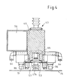
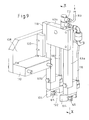
- Fig. 9 reveals, also designed as a U-shaped frame and in the context arranged with the transport bar 43 described manner but carries on the two legs 63a, b respectively only a suction head 65.
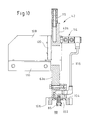
- Each of the two suction cups is within one Cutout 102 arranged on a stop member 104, such as this is shown in Figs. 9 and 10.
- the two stop parts 104 are respectively at the lower end of the leg 63a and 63b mounted such that the respective cutout 102 after is open at the bottom and the associated suction head 65 in unclaimed Condition, ie without object, opposite to the lower limit 106 of the respective stop member 104 protrudes slightly downward, as this particular Fig. 10 shows.
- the lifting device 42 is above the receptacle 16 of each in the removal station 88 located slide 14 by means a side plate 108 and a console 110 on the transport bar 90 attached. Once the respective slide in this station reached, the lifting part 42a is driven down, until the two suction heads 65 on the lying in the recording CD come to the plant. In this case, the two suction heads 65 something compressed with the result that the object with its upper Boundary surface at the lower boundary surface 106 each the two stop members 104 comes to rest and thus a defined position, which also during the following Upward movement of the lifting part 42a is maintained, since the ambient air pressure the object against the two stop parts 104th suppressed. Before the start of the upward movement was on the CD in the recording 16 of the slide 14 acting negative pressure off Service.
- the lifting part 42 a With a connection 112 for a hose 114, which makes the connection to a vacuum source and so on flexible is that they follow the strokes of the lifting part 42a can. From the port 112 there is a distribution of the negative pressure on the suction heads 65 of the two legs 63a and 63b.
- a distributor 114 is provided, of which in each case one Line 116 to the respective suction head 65 goes off.
- the distributor piece 114 is further provided with a branch 116 which via a valve with the outside atmosphere is connectable, so for example, upon transfer of the suction heads 65 of the lifting part 42a carried CD to the suction heads 58a, b of the toothed belt 47 reduce the negative pressure in the suction heads 65 as quickly as possible to be able to.
- the (not shown) valve of the branch 116th is thus opened as soon as the CD in the course of the upward movement the lifting part 42a on the respective suction head pair 58a, b of the Timing belt 47 has come to the plant, possibly even fractions seconds earlier, to reduce the negative pressure in the piping system, at the respective end of a suction head 65 is arranged is to accelerate.
- the connection to the surrounding Atmosphere closed by closing the valve is then the connection to the surrounding Atmosphere closed by closing the valve.
- the lifting parts 42 a, b carried by the first transport bar 43 Lifting device 42 may be formed in a corresponding manner be, taking into account the volume of the systems, each under Low pressure or normal pressure or even overpressure are set need to keep as small as possible, each of the two Hubmaschine 42a and 42b is assigned its own vent valve.
- the second transport bar 90 of the timing belt 47th gradually moved to the removal station 88 of the respective Suction head pair 58a, b recorded CD towards to transport the collecting station 92 and 94, respectively.
- the lifting device 42a can go down again to remove the next CD from the now located in the removal station 88 following slides are moved as soon as the last CD Range of movement of the elevator in the direction of the arrow 91 left.
- each flange 63a, b of the U-frame of the lifting device 42a - in Comparison to two suction heads in the lifting parts 42a, b of the first, feeding transport bar 43 - is therefore possible because the CDs are individually in the recordings of the trolley and thus the removal from the recording much easier This is done by lifting a single CD from one Stack, as in the two separating stations 36, 37 of the Case is.
- the printed CD invariably only in one Removal station 88 successively from there each Slide 14 should be taken out for the Taking only one lifting device 42 to be provided.
- the other end portion of the transport bar 90 are the two Assembled collecting stations 92, 94 for the printed CDs, the can also be used alternately, even at the exchange a full magazine against an empty magazine continuously to continue working.
- Analogous to the arrangement of the separating stations 36, 37 is the collecting station 92 the conveyor belt 29, the collecting station 94 assigned to the conveyor belt 30 such that both stations 92, 94 along the longitudinal course of the transport bar 90 are positioned.
- the at the suction head pairs 58 a, b hanging CDs either step by step to the removal station 92 or transported to the removal station 94.
- the collection station 94 provided with an almost completely filled magazine 32, while in the collecting station 92 an empty magazine located.
- Both magazines are analogous to those already related with the separating stations 36, 37 described manner respectively by the two parts 39a, 39b of a gripper on the foot 33 captured and lifted so far that the upper end of the respective Spindle 34 is at a short distance below the CD is, which in each case on the toothed belt 47 hanging in the respective collecting station, in the specific case the collecting station 94, is located.
- the magazine is by appropriate downward movement the parts 39a, 39b of the gripper lowered until the foot 33 on the conveyor belt 30 is seated. After that, a tight above the conveyor belt 30 located stop, at which the Foot 33 of the magazine 32 rests laterally, away, leaving the With printed CDs filled magazine transported by the conveyor belt 30 can be.
- Fig. 7 shows the situation shortly before the change from the collecting station 94 to collecting station 92.
- the still empty magazine 32 already in the position in which it will record the printed CDs. It is easily possible that both magazines simultaneously the upper end position take, since the upper end of the respective spindle 34 in Although this position only a short distance below the trajectory of the hanging on the suction heads 58a, 58b CDs but does not obstruct the movement of the CDs.
- the ejectors are designed as small, vertically reciprocating pistons, for example, under the action of compressed air against the force of a spring are displaced down and thereby with its lower end against the upper surface of the CD press and thus in a controlled manner by a distance Move down, which in any case is sufficient to the CD from the suction head pair 58a, b carrying it.
- These ejectors 96 may depend on a program or otherwise, for example, depending on the transport movements the respective toothed belt 47 are controlled.
- On Reason for the symmetrical arrangement of the two ejectors to each CD is a guarantee that the CD during the short way, which is to be covered, until in each case located in the Abwerfstation 71 recording 70 of the turntable 44 lies or with the mandrel 34 of the respective magazine 32nd engages, the required alignment for recording or to the spine retains.
- Further ejectors 96 may be on the transport bar 90 between the Removal station 72 and the first in the transport direction 91 of the CDs Collecting station 94 may be provided to, for example, CDs, in the control of the printed image in the station 86 of the Printing machine 10 have turned out to be faulty off to remove the transport stream. In doing so, depending on from the result of the test in the control station 86 (FIG. 1) or in another control station (eg identity) the in the corresponding position between two transport steps of the timing belt 27 each located suction head pairs Pressurized air and actuates the associated ejector 96, including including magazines for the inclusion of this can be provided sorted CDs.
- the admission with compressed air can z. B. in connection with the Abwerfstation 71 described using compressed air connections 64 and -socket 66 done.
- the filled with the CDs to be printed magazines 32 are on Input end 98 of the conveyor belt 29 placed on the upper strand, including those magazines that are in the separation station 37 of the second conveyor belt 30 are emptied.
- Fig. 1 of the drawing shows that the two conveyor belts 29, 30 parallel over a substantial part of their length and run next to each other.
- both conveyor belts 29, 30 are immediately in front of the two Separation stations 36, 37 between the two conveyor belts 29, 30 extending guide rails with an opening 97 provided, whose length in the transport direction 89 slightly bigger than the largest diameter of a magazine 32.
- These existing in the guide rails 98 gap 97 allows every second magazine with unprinted objects from the tape 29 to slide across the tape 30, so that the tape 30 is fed via the belt 29 with magazines.
- All movements of various transport facilities in the area B are mechanically derived from a central drive.
- the step gear for the turntable 44 via a Belt drive driven by the device's central electric motor.
- From the gradual transport movement of the Turntable is the stepwise movement of the toothed belt 47th derived from the first transport bar 43.
- the gradual movement the toothed belt 47 of the second transport bar 90 is from the movement of the toothed belt of the first transport bar derived.
- the pendulum gear for the transfer device 75th is driven by the shaft of the step transmission.
- On the Continuous shaft of the pendulum gear are three curves, which each have a coupling rod the lifting movements the lifting devices 42 on the first and second transport beams and cause the lifting movements of the transfer device.
- At the lifting parts 42a and 42b each have at least one guide rail 118 mounted, which in at least one shoe 120 slides, which as a guide on the fixed Region of the lifting device 42 is mounted.
- the lifting movements transmitting coupling rod engages in each case on the lifting parts or on the lifting parts 42a and 42b carrying the main frame 41st at.
Landscapes
- Sheets, Magazines, And Separation Thereof (AREA)
- Specific Conveyance Elements (AREA)
- Ink Jet (AREA)
Applications Claiming Priority (2)
| Application Number | Priority Date | Filing Date | Title |
|---|---|---|---|
| DE102004012078A DE102004012078A1 (de) | 2004-03-12 | 2004-03-12 | Vorrichtung zum Zuführen und Wegführen von Objekten zu bzw. von einer Maschine zum Dekorieren derselben |
| DE102004012078 | 2004-03-12 |
Publications (1)
| Publication Number | Publication Date |
|---|---|
| EP1574335A1 true EP1574335A1 (fr) | 2005-09-14 |
Family
ID=34813669
Family Applications (1)
| Application Number | Title | Priority Date | Filing Date |
|---|---|---|---|
| EP04026762A Withdrawn EP1574335A1 (fr) | 2004-03-12 | 2004-11-11 | Dispositif pour amener des objets vers- et pour les enlever d'une machine à décorer |
Country Status (5)
| Country | Link |
|---|---|
| US (1) | US20050199143A1 (fr) |
| EP (1) | EP1574335A1 (fr) |
| CN (1) | CN1666940A (fr) |
| DE (1) | DE102004012078A1 (fr) |
| TW (1) | TWI275550B (fr) |
Families Citing this family (12)
| Publication number | Priority date | Publication date | Assignee | Title |
|---|---|---|---|---|
| DE102006003056B4 (de) * | 2006-01-20 | 2014-05-08 | Phoenix Contact Gmbh & Co. Kg | Tintendrucker zum Bedrucken von Gegenständen |
| WO2010098734A1 (fr) * | 2009-02-26 | 2010-09-02 | Ppt Research, Inc. | Compositions inhibant la corrosion |
| CN104567777B (zh) * | 2013-10-18 | 2017-09-26 | 苏州东南碳制品有限公司 | 一种碳刷厚度检测机 |
| DE102014218310B4 (de) | 2014-09-12 | 2017-06-01 | Kba-Kammann Gmbh | Transportvorrichtung für in einer Bearbeitungsmaschine zu bearbeitende und dort bearbeitete Objekte |
| DE102014218313B4 (de) | 2014-09-12 | 2017-05-04 | Kba-Kammann Gmbh | Transportvorrichtung für in einer Bearbeitungsmaschine zu bearbeitende und/oder dort bearbeitete Objekte |
| DE102014218308B4 (de) | 2014-09-12 | 2021-12-23 | Kba-Kammann Gmbh | Transportvorrichtung für in einer Bearbeitungsmaschine zu bearbeitende und/oder dort bearbeitete Objekte |
| DE102014218306A1 (de) | 2014-09-12 | 2016-03-17 | Kba-Kammann Gmbh | Vorrichtung zur Bereitstellung von thermoplastischer Druckfarbe an einer Druckform eines Druckwerks |
| DE102014218314B4 (de) | 2014-09-12 | 2017-06-01 | Kba-Kammann Gmbh | Verfahren zum Betreiben einer Transportvorrichtung für mehrere in einer Bearbeitungsmaschine zu bearbeitende und/oder dort bearbeitete Objekte |
| CN105774207B (zh) * | 2014-12-26 | 2018-12-21 | 深圳富泰宏精密工业有限公司 | 定位装置 |
| DE102016220970B4 (de) | 2016-10-25 | 2022-12-08 | Kba-Kammann Gmbh | Druckmaschine zum Drucken mindestens eines Druckbildes auf eine Bedruckstofffläche |
| DE102017206936A1 (de) | 2017-04-25 | 2018-10-25 | Kba-Kammann Gmbh | Verfahren zum Bedrucken von jeweils eine Mantelfläche und eine Grundfläche aufweisenden Körpern und Vorrichtung zum Überführen mindestens eines solchen Körpers von einer ersten Bearbeitungsposition in eine zweite Bearbeitungsposition |
| JP2020033030A (ja) * | 2018-08-27 | 2020-03-05 | 昭和アルミニウム缶株式会社 | 缶体製造システム |
Citations (2)
| Publication number | Priority date | Publication date | Assignee | Title |
|---|---|---|---|---|
| JPH0858062A (ja) * | 1994-08-19 | 1996-03-05 | Nippon Bunka Seiko Kk | Cd多色印刷装置 |
| US6082256A (en) | 1997-10-14 | 2000-07-04 | Werner Kammann Maschinenfabrik Gmbh | Apparatus and method of decorating articles using a transport screw with a varying screw flight pitch |
Family Cites Families (12)
| Publication number | Priority date | Publication date | Assignee | Title |
|---|---|---|---|---|
| GB1075821A (en) * | 1964-01-18 | 1967-07-12 | Lawrence Engineering Company L | Improvements relating to pallet transfer mechanisms |
| IT1053104B (it) * | 1975-12-19 | 1981-08-31 | Azionaria Costruzioni Acma Spa | Apparato per trasferire..secondo un passo predeterminato..oggetti a un convogliatore di ricezione..gli oggetti provenendo ad intervalli irregolari da un convogliatore di erogazione |
| DE2927038A1 (de) * | 1979-07-04 | 1981-01-15 | Laeis Werke Ag | Putz- und stapelmaschine fuer keramische formlinge |
| NL8501898A (nl) * | 1984-08-17 | 1986-03-17 | Staufner Helmut | Inrichting voor het sorteren van gedrukte geschriften, zoals kranten, tijdschriften, afleveringen, pockets of dergelijke. |
| US4862798A (en) * | 1985-11-04 | 1989-09-05 | American Screen Printing Equipment Company | Cylindrical object screen printer with object centering means |
| US5165340A (en) * | 1991-03-06 | 1992-11-24 | Karlyn William M | Multicolor printing system for the silk-screen printing of compact discs |
| US5644895A (en) * | 1995-05-01 | 1997-07-08 | Johnson & Johnson Vision Products, Inc. | Packaging arrangement |
| SG50380A1 (en) * | 1995-12-09 | 1998-07-20 | Advanced Systems Automation Pt | Pick and place system |
| US5730048A (en) * | 1997-01-06 | 1998-03-24 | Averill; Michael J. | System for the printing of small flat objects using direct rotary printing apparatus |
| FR2780961B1 (fr) * | 1998-07-10 | 2000-10-13 | Dubuit Mach | Dispositifs de chargement et dechargement pour machine d'impression |
| FR2800006B1 (fr) * | 1999-10-22 | 2002-01-18 | Dubuit Mach | MACHINE A IMPRIMER A SUPPORT PORTE-OBJET COMPRENANT DES MOYENS DE SOULEVEMENT DE l'OBJET, ET SUPPORT PORTE-OBJET POUR MACHINE A IMPRIMER |
| US6991524B1 (en) * | 2000-07-07 | 2006-01-31 | Disc Go Technologies Inc. | Method and apparatus for reconditioning digital discs |
-
2004
- 2004-03-12 DE DE102004012078A patent/DE102004012078A1/de not_active Withdrawn
- 2004-11-11 EP EP04026762A patent/EP1574335A1/fr not_active Withdrawn
- 2004-12-02 US US11/002,056 patent/US20050199143A1/en not_active Abandoned
-
2005
- 2005-01-11 CN CN200510003935.6A patent/CN1666940A/zh active Pending
- 2005-01-14 TW TW094101066A patent/TWI275550B/zh not_active IP Right Cessation
Patent Citations (2)
| Publication number | Priority date | Publication date | Assignee | Title |
|---|---|---|---|---|
| JPH0858062A (ja) * | 1994-08-19 | 1996-03-05 | Nippon Bunka Seiko Kk | Cd多色印刷装置 |
| US6082256A (en) | 1997-10-14 | 2000-07-04 | Werner Kammann Maschinenfabrik Gmbh | Apparatus and method of decorating articles using a transport screw with a varying screw flight pitch |
Non-Patent Citations (1)
| Title |
|---|
| PATENT ABSTRACTS OF JAPAN vol. 1996, no. 07 31 July 1996 (1996-07-31) * |
Also Published As
| Publication number | Publication date |
|---|---|
| TW200530104A (en) | 2005-09-16 |
| CN1666940A (zh) | 2005-09-14 |
| US20050199143A1 (en) | 2005-09-15 |
| DE102004012078A1 (de) | 2005-09-29 |
| TWI275550B (en) | 2007-03-11 |
Similar Documents
| Publication | Publication Date | Title |
|---|---|---|
| DE2814686C2 (de) | Fördervorrichtung | |
| DE69005021T2 (de) | Schwenkbare Werkstück-Entnahmevorrichtung. | |
| DE2543692C2 (de) | Vorrichtung zur Verwendung beim Entleeren von Briefumschlägen | |
| EP2049063B1 (fr) | Dispositif et procédé d'éjection d'au moins une capsule. | |
| DE102006023111A1 (de) | Vorrichtung zum Beschichten von Objekten | |
| DE2125991A1 (de) | Verfahren und Vorrichtung zum Transport gestapelter flacher Gegenstände in Aufeinanderfolge zu einem Auffangen | |
| EP1574335A1 (fr) | Dispositif pour amener des objets vers- et pour les enlever d'une machine à décorer | |
| DE1431610B1 (de) | Vorrichtung zum Zu- und Abfoerdern von zu bedruckenden Behaeltern | |
| DE2124748A1 (de) | Einrichtung zum Entgraten des Halses von Hohlkörpern aus Kunststoff | |
| DE2058606B2 (de) | Vorrichtung zum kontinuierlichen Fördern und Ausrichten von vereinzelten Bogen | |
| DE2155114C2 (de) | Transportvorrichtung zum Führen einer Anzahl identischer Wagen in einem Kreislauf | |
| EP2776347B1 (fr) | Dispositif d'alimentation pour fermetures de contenant | |
| DE2924827A1 (de) | Vorrichtung zum palettieren von gefuellten saecken | |
| DE2756473C2 (fr) | ||
| DE19511296C2 (de) | Vorrichtung zum Anheben und Abtransportieren flächiger Gegenstände | |
| EP0751086B1 (fr) | Dispositif pour extraire les inclusions d'air de piles de papier | |
| EP1243529B1 (fr) | Dispositif d'approvisionnement et/ou d'évacuation de magasins remplis d'objets | |
| DE1561121A1 (de) | Blattzufuehrungsvorrichtung | |
| DE597552C (de) | Maschine zum Sortieren von Schriftstuecken u. dgl. | |
| DE1006331B (de) | Foerder- und Verladeeinrichtung fuer eine Vielzahl von gleichmaessigen, insbesondere leicht zerbrechlichen Gegenstaenden | |
| DE3135549C2 (fr) | ||
| DE69907999T2 (de) | Sauggreifereinrichtung | |
| DE102018119543B4 (de) | Spinnzylinderschleifmaschine | |
| DE2009138A1 (en) | Sheet stamping transfer device | |
| DE10355261A1 (de) | Bogen verarbeitende Rotationsdruckmaschine mit einer Bogenbremse |
Legal Events
| Date | Code | Title | Description |
|---|---|---|---|
| PUAI | Public reference made under article 153(3) epc to a published international application that has entered the european phase |
Free format text: ORIGINAL CODE: 0009012 |
|
| AK | Designated contracting states |
Kind code of ref document: A1 Designated state(s): AT BE BG CH CY CZ DE DK EE ES FI FR GB GR HU IE IS IT LI LU MC NL PL PT RO SE SI SK TR |
|
| AX | Request for extension of the european patent |
Extension state: AL HR LT LV MK YU |
|
| 17P | Request for examination filed |
Effective date: 20050810 |
|
| AKX | Designation fees paid |
Designated state(s): DE FR IT |
|
| 17Q | First examination report despatched |
Effective date: 20090930 |
|
| GRAP | Despatch of communication of intention to grant a patent |
Free format text: ORIGINAL CODE: EPIDOSNIGR1 |
|
| STAA | Information on the status of an ep patent application or granted ep patent |
Free format text: STATUS: THE APPLICATION IS DEEMED TO BE WITHDRAWN |
|
| 18D | Application deemed to be withdrawn |
Effective date: 20101001 |