EP1574392A2 - Feu latéral clignotant - Google Patents
Feu latéral clignotant Download PDFInfo
- Publication number
- EP1574392A2 EP1574392A2 EP05005308A EP05005308A EP1574392A2 EP 1574392 A2 EP1574392 A2 EP 1574392A2 EP 05005308 A EP05005308 A EP 05005308A EP 05005308 A EP05005308 A EP 05005308A EP 1574392 A2 EP1574392 A2 EP 1574392A2
- Authority
- EP
- European Patent Office
- Prior art keywords
- light
- side indicator
- light guide
- vehicle
- light source
- Prior art date
- Legal status (The legal status is an assumption and is not a legal conclusion. Google has not performed a legal analysis and makes no representation as to the accuracy of the status listed.)
- Granted
Links
Images
Classifications
-
- B—PERFORMING OPERATIONS; TRANSPORTING
- B60—VEHICLES IN GENERAL
- B60Q—ARRANGEMENT OF SIGNALLING OR LIGHTING DEVICES, THE MOUNTING OR SUPPORTING THEREOF OR CIRCUITS THEREFOR, FOR VEHICLES IN GENERAL
- B60Q1/00—Arrangement of optical signalling or lighting devices, the mounting or supporting thereof or circuits therefor
- B60Q1/26—Arrangement of optical signalling or lighting devices, the mounting or supporting thereof or circuits therefor the devices being primarily intended to indicate the vehicle, or parts thereof, or to give signals, to other traffic
- B60Q1/2661—Arrangement of optical signalling or lighting devices, the mounting or supporting thereof or circuits therefor the devices being primarily intended to indicate the vehicle, or parts thereof, or to give signals, to other traffic mounted on parts having other functions
- B60Q1/2665—Arrangement of optical signalling or lighting devices, the mounting or supporting thereof or circuits therefor the devices being primarily intended to indicate the vehicle, or parts thereof, or to give signals, to other traffic mounted on parts having other functions on rear-view mirrors
-
- B—PERFORMING OPERATIONS; TRANSPORTING
- B60—VEHICLES IN GENERAL
- B60R—VEHICLES, VEHICLE FITTINGS, OR VEHICLE PARTS, NOT OTHERWISE PROVIDED FOR
- B60R1/00—Optical viewing arrangements; Real-time viewing arrangements for drivers or passengers using optical image capturing systems, e.g. cameras or video systems specially adapted for use in or on vehicles
- B60R1/12—Mirror assemblies combined with other articles, e.g. clocks
- B60R1/1207—Mirror assemblies combined with other articles, e.g. clocks with lamps; with turn indicators
-
- F—MECHANICAL ENGINEERING; LIGHTING; HEATING; WEAPONS; BLASTING
- F21—LIGHTING
- F21S—NON-PORTABLE LIGHTING DEVICES; SYSTEMS THEREOF; VEHICLE LIGHTING DEVICES SPECIALLY ADAPTED FOR VEHICLE EXTERIORS
- F21S43/00—Signalling devices specially adapted for vehicle exteriors, e.g. brake lamps, direction indicator lights or reversing lights
- F21S43/20—Signalling devices specially adapted for vehicle exteriors, e.g. brake lamps, direction indicator lights or reversing lights characterised by refractors, transparent cover plates, light guides or filters
- F21S43/235—Light guides
Definitions
- the invention relates to a side indicator for installation in the cap of an exterior rearview mirror for motor vehicles according to the preamble of claim 1.
- Such a side indicator is known for example from EP 1 195 296 A2. These described side indicator is below with reference to Figures 1 and 2 still explained in detail.
- An essential aspect of this known side indicator is that they at least comprises a rod-shaped light guide, which in the installed state is approximately horizontal from the remote from the vehicle outside of the cap extends to the vehicle.
- a preferably designed as a light emitting diode (LED) light source is arranged so that its light in the closer to the vehicle end of the Fiber optic coupled and from this on a corresponding to the curvature of the cap the exterior rearview mirror curved path to its opposite Forward side is forwarded to the incoming light in a prescribed by law Angular range transverse to the direction of travel and emitted obliquely backwards becomes.
- LED light emitting diode
- a disadvantage of this arrangement is that the light source is an extremely bright and thus expensive light-emitting diode must be used, so that in spite of the forwarding of the light taking place in the light guide outcoupling of light components at its Auskoppel front end enough light arrives at the brightness requirements prescribed by law in terms of illumination of the hilltop warmed up to the direction of travel and obliquely to meet the rearwardly extending angle range.
- the invention has the object, a side indicator of the above be further developed so that the legal requirements with less bright and therefore less expensive light sources, in particular light-emitting diodes, met can be.
- the invention provides the features set out in claim 1 in front.
- the light of the at least one first Light source is coupled into the end of the light guide farther away from the vehicle, which forwards it to its front end closer to the vehicle.
- the at least one light source of one LED are formed, which has a much lower brightness than the light emitting diode, which must be used in the prior art, and therefore also considerably cheaper is.
- the brightness but also be significantly lower can, as required by the prior art single LED.
- the side indicator according to the invention is that the light guide is no longer in the outermost end of the vehicle must lie remote side of the cap of the exterior rearview mirror. In This end region must be arranged only the at least one second light source, to ensure the legally prescribed angle range illumination.
- the Depth of such a light source is much lower than that of a light guide, the gives sufficient light intensity to its extreme end.
- Straight from the Vehicle remote end portion of the exterior rearview mirror cap is but in Particularly critical in this respect, because when adjusting the rearview mirror in it must move the vertical outer edge of the mirror glass.
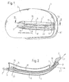
- Fig. 1 shows a perspective, seen in the direction of travel view of a Exterior rearview mirror 1 for motor vehicles, a cap 2 with an elongated, in the installed state substantially horizontally extending light exit opening 3, in which from the rear or inside a side indicator 4 installed is.
- the light disk 6 shown in FIGS. 2, 3 and 4, which the light exit opening 3 closes, is omitted in Fig. 1 for the sake of clarity.
- the side indicator 4 has a strip-shaped structure, which comes about thereby, that in the vertical direction alternately different, elongated, extending horizontally Areas are provided by two trained as light rods light guides 8, 8 'and an intermediate, strip-shaped region 10 are formed.
- each rod-shaped light guide 8, 8 'a LED 15 is arranged so that the light emitted by her in the associated rod-shaped light guide 8, 8 'coupled and from this to its opposite Front end 16, 16 'is forwarded, although over the length of the light guide 8, 8' constantly parts of this luminous flux by scattering and reflection effects across the Longitudinal direction of the light guide 8, 8 'are coupled out and exit through the lens 6.
- each of the rod-shaped Optical waveguide 8, 8 ' Provided with a bevel 17, 17' serving as a decoupling surface, whose inclination is chosen so that the light exiting through them in the law prescribed solid angle range, d. H. essentially transverse to the direction of travel and is radiated obliquely backwards, as indicated by the arrows F.
- a side indicator 34 of the invention optionally a single rod-shaped light guide 38 or more, corresponding to FIG. 1 arranged rod-shaped light guide or a single (not shown) disc-shaped Optical fiber may include, the horizontal length then approximately equal to the rod-shaped Optical fiber is and in the vertical direction about the same or a larger Height as the rod-shaped light guide extends, so that then in Fig. 1 between the Light guides 8, 8 'lying strip-shaped region 10 is omitted and by a part of the disc-shaped light guide is replaced.
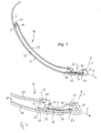
- a light source formed by a first light source 52 is arranged so that the light emitted by it is coupled into the front end of the light guide 38 and is forwarded by this to its opposite front end 44. It follows the Although light propagation of the curvature of the light guide 38, but on this way constantly portions of the propagating light from the light guide 38 either directly coupled forwards to the lens 36 or back to the reflector 50, the reflects them so that they pass through the light guide 38 and the lens 36 step outside.
- the inventive Side indicator 34 visible in Fig. 1 in projection, by the at least one Optical fiber 38 (or through multiple optical fibers) deposited surface and is for oncoming Road users clearly visible.
- the due to legal regulations in the indicated by the arrows F angle range to be emitted light is emitted by at least one second light source 54, the is also formed by a light emitting diode and how the light guide 38 and the first light source 52 is located approximately in the plane of Figs. 3 and 4.
- This second light source 54 is in extension of the predetermined by the light guide 50 direction in a clear Distance D from the first light source 52 is arranged, its meaning in the following will be explained in more detail
- Each of the light sources 52, 54 is mounted on a carrier board 56 and 58, respectively the power supply terminals, not shown for driving these light sources in Wears shape of a printed circuit.
- the opening angle of the light cone emitted by the second light source 54 is through a lens or lens assembly integrally connected to the lens 36 56 changed so that the desired light distribution is achieved in the area F-F becomes.
- connection area between the carrier boards 56 and 58 is also located the access opening 62 to the interior of the lamp housing, by a the above-mentioned Countersunk 65 having lid member 68 is closed.
- the back wall the luminaire housing forming reflector 50 includes in the area of the vehicle remote end face 44 of the light guide 38 an angled, forward to Lens 36 toward extending wall 70 which limits the access opening 62 on the one hand and on the other hand has a through opening 72 through which the end of Fiber optic 38 therethrough so that the end face of the light guide 38 of the light source 56 is directly opposite.
- the wall 70 is followed by another part of the reflector 50, on its front side preferably also coated with a mirror layer and as a cover 74 and forms with the wall 70 at such an angle that it is approximately parallel to Lens 36 extends, wherein it the light sources 52,54, their support plates 56,58 and the Connecting line 60 so hidden that they are not visible in the direction of Figure 1.
- the lens 36 At its farthest from the vehicle end the lens 36 is with provided an obliquely rear angled passage window 76, on its inside has an optically active structure.
- the output from the second light source 54 Light is generated by means of a reflector arrangement, which is made by a beveled end part 78 of the reflector 50 belonging to cover member 74 and the angled on the Inner side provided with a reflective layer end 80 of the lens 36 is formed is focused on the passage window 76, the optically active structure of Lens and / or scattering elements may be formed for the desired intensity distribution of the light emitted in the angular range indicated by the arrows F, F provides.
- rod-shaped light guide 38 may be arranged one above the other, in which case preferably each of them is associated with a first light source 52 and a second light source 54 is.
- All first light sources 52 are then preferably on one and the same carrier board 56th mounted and electrically conductive by a provided on this printed circuit with each other connected.
- Arrangements are also conceivable in which a single carrier board is shaped to include both the first light sources 52 and the second light sources 54 carries.
- the connection line 60 is then in the form of a printed circuit formed this carrier board.
- the invention provides a side indicator for installation in the exterior rearview mirror a motor vehicle which has a very small overall depth, which in the area, in which the outer edge of the pivotable mirror disk during adjustment must move, is even further diminished.
- the side indicator according to the invention from very few Components, namely the lens 36, at the same time the front wall of the lamp housing forms and integrally connected to the passage window 76 and the reflector part 80 is, the reflector 50, which serves as a rear wall of the lamp housing and with the reflector assembly 51, the end of the light guide 38 supporting wall 70, the cover 74 and the reflector part 78 is integrally connected, the light guide 36 and the light sources 52 and 54 carrying carrier boards 56 and 58, the connecting line 60 and the Cover element 68.
- the invisible in the figures upper and lower walls of the Luminaire housing may be from angled parts of the rear wall 50 and / or the lens 36 are formed.
Landscapes
- Engineering & Computer Science (AREA)
- Mechanical Engineering (AREA)
- Multimedia (AREA)
- Lighting Device Outwards From Vehicle And Optical Signal (AREA)
- Non-Portable Lighting Devices Or Systems Thereof (AREA)
Applications Claiming Priority (2)
| Application Number | Priority Date | Filing Date | Title |
|---|---|---|---|
| DE102004012052 | 2004-03-11 | ||
| DE102004012052A DE102004012052A1 (de) | 2004-03-11 | 2004-03-11 | Seitenblinkleuchte |
Publications (3)
| Publication Number | Publication Date |
|---|---|
| EP1574392A2 true EP1574392A2 (fr) | 2005-09-14 |
| EP1574392A3 EP1574392A3 (fr) | 2006-01-25 |
| EP1574392B1 EP1574392B1 (fr) | 2008-05-21 |
Family
ID=34813668
Family Applications (1)
| Application Number | Title | Priority Date | Filing Date |
|---|---|---|---|
| EP05005308A Expired - Lifetime EP1574392B1 (fr) | 2004-03-11 | 2005-03-10 | Feu latéral clignotant |
Country Status (3)
| Country | Link |
|---|---|
| EP (1) | EP1574392B1 (fr) |
| DE (2) | DE102004012052A1 (fr) |
| ES (1) | ES2311894T3 (fr) |
Cited By (2)
| Publication number | Priority date | Publication date | Assignee | Title |
|---|---|---|---|---|
| DE102012100732A1 (de) * | 2011-05-31 | 2012-12-06 | SMR Patents S.à.r.l. | Außenspiegel mit Spiegelblinker |
| EP2743131A3 (fr) * | 2012-12-14 | 2018-03-28 | SL Corporation | Lampe pour véhicule |
Families Citing this family (2)
| Publication number | Priority date | Publication date | Assignee | Title |
|---|---|---|---|---|
| DE102012104529B4 (de) * | 2012-05-25 | 2025-10-09 | SMR Patents S.à.r.l. | Lichtleiteinheit |
| KR101453936B1 (ko) | 2014-03-14 | 2014-10-22 | 에스엘 주식회사 | 차량용 램프 |
Family Cites Families (4)
| Publication number | Priority date | Publication date | Assignee | Title |
|---|---|---|---|---|
| DE20001407U1 (de) * | 2000-01-27 | 2000-03-16 | Reitter & Schefenacker GmbH & Co. KG, 73730 Esslingen | Außenrückblickspiegel für Fahrzeuge, vorzugsweise für Kraftfahrzeuge |
| ES2168071B1 (es) * | 2000-07-12 | 2003-07-16 | Barros Alejandro Rodriguez | Retrovisor modular con señales multiples intercambiables para vehiculos de 2, 3, 4 o mas ruedas. |
| DE10238073A1 (de) * | 2002-08-21 | 2004-03-04 | Hella Kg Hueck & Co. | Fahrzeugleuchte |
| DE20219483U1 (de) * | 2002-12-16 | 2003-05-08 | FER Fahrzeugelektrik GmbH, 99817 Eisenach | Fahrzeugleuchte |
-
2004
- 2004-03-11 DE DE102004012052A patent/DE102004012052A1/de not_active Ceased
-
2005
- 2005-03-10 EP EP05005308A patent/EP1574392B1/fr not_active Expired - Lifetime
- 2005-03-10 ES ES05005308T patent/ES2311894T3/es not_active Expired - Lifetime
- 2005-03-10 DE DE502005004160T patent/DE502005004160D1/de not_active Expired - Lifetime
Cited By (2)
| Publication number | Priority date | Publication date | Assignee | Title |
|---|---|---|---|---|
| DE102012100732A1 (de) * | 2011-05-31 | 2012-12-06 | SMR Patents S.à.r.l. | Außenspiegel mit Spiegelblinker |
| EP2743131A3 (fr) * | 2012-12-14 | 2018-03-28 | SL Corporation | Lampe pour véhicule |
Also Published As
| Publication number | Publication date |
|---|---|
| DE102004012052A1 (de) | 2005-10-06 |
| EP1574392B1 (fr) | 2008-05-21 |
| EP1574392A3 (fr) | 2006-01-25 |
| ES2311894T3 (es) | 2009-02-16 |
| DE502005004160D1 (de) | 2008-07-03 |
Similar Documents
| Publication | Publication Date | Title |
|---|---|---|
| EP1195296B1 (fr) | Feu latéral indicateur de direction | |
| EP1854667B1 (fr) | Dispositif d'éclairage et rétroviseur extérieur avec un dispositif d'éclairage | |
| EP1640656B1 (fr) | Guides de lumière pour lampes, notamment pour lampes de véhicule | |
| EP2354637B1 (fr) | Dispositif d'éclairage pour véhicules | |
| DE102008048765B4 (de) | Beleuchtungsvorrichtung für Kraftfahrzeuge | |
| DE102014211874B4 (de) | Beleuchtungseinrichtung eines Kraftfahrzeugs | |
| DE102014205994B4 (de) | Lichtmodul mit Halbleiterlichtquelle und Vorsatzoptik und Kraftfahrzeugscheinwerfer mit einem solchen Lichtmodul | |
| DE102004054732B4 (de) | Lichtleiteranordung | |
| EP1391755B1 (fr) | Feu de véhicule | |
| DE102007010023A1 (de) | Fahrzeugleuchte | |
| AT518118B1 (de) | Beleuchtungseinheit für ein Kraftfahrzeug | |
| EP1167870A2 (fr) | Feu pour véhicule | |
| EP1225385A2 (fr) | Lampe, notamment feu de signalisation pour véhicules | |
| EP3210827A1 (fr) | Feu de véhicule | |
| EP1085253A2 (fr) | Lampe, notamment pour véhicules automobiles | |
| DE102017105838A1 (de) | Beleuchtungseinrichtung eines Kraftfahrzeugs mit einer Lichtleiteranordnung | |
| DE20219483U1 (de) | Fahrzeugleuchte | |
| DE20017038U1 (de) | Seitenblinkleuchte | |
| EP2500754B1 (fr) | Dispositif d'éclairage pour véhicule automobile | |
| DE202006003392U1 (de) | Fahrzeugleuchte | |
| DE10314257A1 (de) | Leuchte für Fahrzeuge | |
| DE102007038470B4 (de) | Beleuchtungseinrichtung für Fahrzeuge | |
| EP1574392B1 (fr) | Feu latéral clignotant | |
| DE20312518U1 (de) | Fahrzeugleuchte | |
| DE10314357A1 (de) | Kraftfahrzeugleuchte, insbesondere Zusatzbremsleuchte |
Legal Events
| Date | Code | Title | Description |
|---|---|---|---|
| PUAI | Public reference made under article 153(3) epc to a published international application that has entered the european phase |
Free format text: ORIGINAL CODE: 0009012 |
|
| AK | Designated contracting states |
Kind code of ref document: A2 Designated state(s): AT BE BG CH CY CZ DE DK EE ES FI FR GB GR HU IE IS IT LI LT LU MC NL PL PT RO SE SI SK TR |
|
| AX | Request for extension of the european patent |
Extension state: AL BA HR LV MK YU |
|
| PUAL | Search report despatched |
Free format text: ORIGINAL CODE: 0009013 |
|
| AK | Designated contracting states |
Kind code of ref document: A3 Designated state(s): AT BE BG CH CY CZ DE DK EE ES FI FR GB GR HU IE IS IT LI LT LU MC NL PL PT RO SE SI SK TR |
|
| AX | Request for extension of the european patent |
Extension state: AL BA HR LV MK YU |
|
| 17P | Request for examination filed |
Effective date: 20060329 |
|
| 17Q | First examination report despatched |
Effective date: 20060824 |
|
| AKX | Designation fees paid |
Designated state(s): DE ES FR |
|
| GRAP | Despatch of communication of intention to grant a patent |
Free format text: ORIGINAL CODE: EPIDOSNIGR1 |
|
| GRAS | Grant fee paid |
Free format text: ORIGINAL CODE: EPIDOSNIGR3 |
|
| GRAA | (expected) grant |
Free format text: ORIGINAL CODE: 0009210 |
|
| AK | Designated contracting states |
Kind code of ref document: B1 Designated state(s): DE ES FR |
|
| REF | Corresponds to: |
Ref document number: 502005004160 Country of ref document: DE Date of ref document: 20080703 Kind code of ref document: P |
|
| RAP2 | Party data changed (patent owner data changed or rights of a patent transferred) |
Owner name: TRUCK-LITE EUROPE GMBH |
|
| REG | Reference to a national code |
Ref country code: ES Ref legal event code: FG2A Ref document number: 2311894 Country of ref document: ES Kind code of ref document: T3 |
|
| PLBE | No opposition filed within time limit |
Free format text: ORIGINAL CODE: 0009261 |
|
| STAA | Information on the status of an ep patent application or granted ep patent |
Free format text: STATUS: NO OPPOSITION FILED WITHIN TIME LIMIT |
|
| 26N | No opposition filed |
Effective date: 20090224 |
|
| REG | Reference to a national code |
Ref country code: FR Ref legal event code: PLFP Year of fee payment: 11 |
|
| REG | Reference to a national code |
Ref country code: FR Ref legal event code: PLFP Year of fee payment: 12 |
|
| REG | Reference to a national code |
Ref country code: FR Ref legal event code: PLFP Year of fee payment: 13 |
|
| REG | Reference to a national code |
Ref country code: FR Ref legal event code: PLFP Year of fee payment: 14 |
|
| PGFP | Annual fee paid to national office [announced via postgrant information from national office to epo] |
Ref country code: FR Payment date: 20240320 Year of fee payment: 20 |
|
| PGFP | Annual fee paid to national office [announced via postgrant information from national office to epo] |
Ref country code: DE Payment date: 20240525 Year of fee payment: 20 |
|
| PGFP | Annual fee paid to national office [announced via postgrant information from national office to epo] |
Ref country code: ES Payment date: 20240417 Year of fee payment: 20 |
|
| REG | Reference to a national code |
Ref country code: DE Ref legal event code: R071 Ref document number: 502005004160 Country of ref document: DE |
|
| REG | Reference to a national code |
Ref country code: ES Ref legal event code: FD2A Effective date: 20250326 |
|
| PG25 | Lapsed in a contracting state [announced via postgrant information from national office to epo] |
Ref country code: ES Free format text: LAPSE BECAUSE OF EXPIRATION OF PROTECTION Effective date: 20250311 |