EP1574688A1 - Mechanisches Antriebssystem für ein Hilfsaggregats-Getriebe - Google Patents
Mechanisches Antriebssystem für ein Hilfsaggregats-Getriebe Download PDFInfo
- Publication number
- EP1574688A1 EP1574688A1 EP05251096A EP05251096A EP1574688A1 EP 1574688 A1 EP1574688 A1 EP 1574688A1 EP 05251096 A EP05251096 A EP 05251096A EP 05251096 A EP05251096 A EP 05251096A EP 1574688 A1 EP1574688 A1 EP 1574688A1
- Authority
- EP
- European Patent Office
- Prior art keywords
- shaft
- bevel gear
- gear
- tower
- lay
- Prior art date
- Legal status (The legal status is an assumption and is not a legal conclusion. Google has not performed a legal analysis and makes no representation as to the accuracy of the status listed.)
- Granted
Links
- 230000001154 acute effect Effects 0.000 description 1
- 230000008878 coupling Effects 0.000 description 1
- 238000010168 coupling process Methods 0.000 description 1
- 238000005859 coupling reaction Methods 0.000 description 1
- 239000000446 fuel Substances 0.000 description 1
Images


Classifications
-
- F—MECHANICAL ENGINEERING; LIGHTING; HEATING; WEAPONS; BLASTING
- F02—COMBUSTION ENGINES; HOT-GAS OR COMBUSTION-PRODUCT ENGINE PLANTS
- F02C—GAS-TURBINE PLANTS; AIR INTAKES FOR JET-PROPULSION PLANTS; CONTROLLING FUEL SUPPLY IN AIR-BREATHING JET-PROPULSION PLANTS
- F02C7/00—Features, components parts, details or accessories, not provided for in, or of interest apart form groups F02C1/00 - F02C6/00; Air intakes for jet-propulsion plants
- F02C7/32—Arrangement, mounting, or driving, of auxiliaries
-
- F—MECHANICAL ENGINEERING; LIGHTING; HEATING; WEAPONS; BLASTING
- F02—COMBUSTION ENGINES; HOT-GAS OR COMBUSTION-PRODUCT ENGINE PLANTS
- F02C—GAS-TURBINE PLANTS; AIR INTAKES FOR JET-PROPULSION PLANTS; CONTROLLING FUEL SUPPLY IN AIR-BREATHING JET-PROPULSION PLANTS
- F02C7/00—Features, components parts, details or accessories, not provided for in, or of interest apart form groups F02C1/00 - F02C6/00; Air intakes for jet-propulsion plants
- F02C7/36—Power transmission arrangements between the different shafts of the gas turbine plant, or between the gas-turbine plant and the power user
-
- F—MECHANICAL ENGINEERING; LIGHTING; HEATING; WEAPONS; BLASTING
- F05—INDEXING SCHEMES RELATING TO ENGINES OR PUMPS IN VARIOUS SUBCLASSES OF CLASSES F01-F04
- F05D—INDEXING SCHEME FOR ASPECTS RELATING TO NON-POSITIVE-DISPLACEMENT MACHINES OR ENGINES, GAS-TURBINES OR JET-PROPULSION PLANTS
- F05D2260/00—Function
- F05D2260/40—Transmission of power
- F05D2260/403—Transmission of power through the shape of the drive components
- F05D2260/4031—Transmission of power through the shape of the drive components as in toothed gearing
-
- F—MECHANICAL ENGINEERING; LIGHTING; HEATING; WEAPONS; BLASTING
- F05—INDEXING SCHEMES RELATING TO ENGINES OR PUMPS IN VARIOUS SUBCLASSES OF CLASSES F01-F04
- F05D—INDEXING SCHEME FOR ASPECTS RELATING TO NON-POSITIVE-DISPLACEMENT MACHINES OR ENGINES, GAS-TURBINES OR JET-PROPULSION PLANTS
- F05D2260/00—Function
- F05D2260/50—Kinematic linkage, i.e. transmission of position
- F05D2260/53—Kinematic linkage, i.e. transmission of position using gears
-
- Y—GENERAL TAGGING OF NEW TECHNOLOGICAL DEVELOPMENTS; GENERAL TAGGING OF CROSS-SECTIONAL TECHNOLOGIES SPANNING OVER SEVERAL SECTIONS OF THE IPC; TECHNICAL SUBJECTS COVERED BY FORMER USPC CROSS-REFERENCE ART COLLECTIONS [XRACs] AND DIGESTS
- Y10—TECHNICAL SUBJECTS COVERED BY FORMER USPC
- Y10T—TECHNICAL SUBJECTS COVERED BY FORMER US CLASSIFICATION
- Y10T74/00—Machine element or mechanism
- Y10T74/19—Gearing
- Y10T74/19642—Directly cooperating gears
- Y10T74/19674—Spur and bevel
Definitions
- the present invention relates to gas turbine engines in general, and to apparatus for driving an accessory gearbox in particular.
- Aircraft powered by gas turbine engines very often include a mechanically driven accessory gearbox for driving accessory systems such as fuel pumps, scavenge pumps, electrical generators, hydraulic pumps, etc.
- the power requirements of the accessory gearbox continue to increase as the number of electrical systems within the aircraft increase.
- the accessory gearbox has been driven by a mechanical system connected to the drive shaft (i.e., the "high pressure drive shaft") extending between the high-pressure turbine and the high-pressure compressor of the gas turbine engine.
- the ability to tap power off of the high-pressure drive shaft is limited, however. What is needed is an apparatus for mechanically driving an accessory gearbox that can accommodate the higher power requirements of modern aircraft.
- a mechanical drive system for an accessory gearbox of a gas turbine engine has a high-pressure drive shaft and a low-pressure drive shaft.
- a first tower shaft is driven by the high-pressure drive shaft.
- a second tower shaft is driven by the low-pressure drive shaft.
- a first lay shaft is driven by the first tower shaft, and is connected to the accessory gearbox.
- a second lay shaft is driven by the second tower shaft, and is connected to the accessory gearbox.
- One of the advantages of the present invention mechanical drive system for an accessory gearbox is that it provides increased versatility and capability over prior art mechanical drive systems that utilize a single tower shaft engaged with the high-pressure drive shaft.
- the present invention has the capacity to draw power off of the low-pressure drive shaft and the high-pressure shaft alternatively, or at the same time.
- a gas turbine engine 10 is diagrammatically shown.
- the engine includes a high-pressure drive shaft 12, a low-pressure drive shaft 14, a low-pressure compressor 16, a high-pressure compressor 18, a high-pressure turbine 20, a low-pressure turbine 22, an accessory gearbox 24, and a mechanical drive system 26 for the accessory gearbox 24.
- the drive shafts 12,14, compressor sections 16,18, and turbine sections 20,22 are centered about an axially extending engine centerline 28.
- the low-pressure compressor 16 is disposed axially forward of the high-pressure compressor 18, and the high pressure turbine 20 is positioned forward of the low-pressure turbine 22.
- the term forward is used to indicate position along the axially extending engine centerline.
- a first component "forward" of a second component is positioned closer to the inlet 30 of the engine 10.
- the second component is positioned "aft" of the first component. In most instances, gas flow traveling through the core of the engine 10 encounters the forward component before it encounters the aft component.
- the low-pressure and high-pressure compressor sections 16,18 and the high and low-pressure turbine sections 20,22 each includes a plurality of stator and rotor stages.
- the high-pressure drive shaft 12 is connected to and extends between the high-pressure compressor 18 and the high-pressure turbine 20.
- the low-pressure drive shaft 14 is connected to and extends between the low-pressure compressor 16 and the low-pressure turbine 22.
- the high-pressure drive shaft 12 and the low-pressure drive shaft 14 rotate about the axially extending engine centerline 28.
- the drive shafts 12,14 are diagrammatically shown in FIG.1 as concentric cylinders to simply illustrate the relationship between the components. Most low-pressure and high-pressure drive shafts are concentric, but have relatively complex geometries to accommodate all of the various components attached thereto and disposed adjacent thereto.
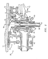
- the portions of the drive shafts 12,14 shown in FIG.2 is illustrated with geometries more typical of those actually used within gas turbine engines.
- the mechanical drive system 26 for the accessory gearbox 24 includes a low-pressure drive shaft gear arrangement 32 ("LPDS gear arrangement”), a high-pressure drive shaft gear arrangement 34 ("HPDS gear arrangement”), a first tower shaft 36, a second tower shaft 38, a first angle gear arrangement 40, a second angle gear arrangement 42, a first lay shaft 44, and a second lay shaft 46.
- the LPDS gear arrangement 32 includes a first spur gear 43, a second spur gear 45, an intermediate shaft 47, a first bevel gear 48, and a second bevel gear 50.
- the first spur gear is fixed (e.g., by one or more splines) to the low-pressure drive shaft 14.
- the second spur gear 45 and the first bevel gear 48 are attached to the intermediate shaft 47.
- the second spur gear 45 is engaged with the first spur gear 43.
- the first bevel gear 48 is engaged with the second bevel gear 50, which is fixed to the second tower shaft 38.
- the HPDS gear arrangement 34 includes a third bevel gear 52 and a fourth bevel gear 54.
- the third bevel gear 52 is fixed (e.g., by one or more splines) to the high-pressure drive shaft 12.
- the third bevel gear 52 is engaged with the fourth bevel gear 54, which is fixed to the first tower shaft 36.
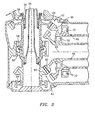
- the first and second tower shafts 36,38 are concentrically arranged and rotatable about a lengthwise extending axis 56.
- the axis 56 is typically oriented perpendicular to (or at an acute angle therefrom) the engine centerline 28.
- the second tower shaft 38 is disposed radially outside of the first tower shaft 36 for substantially all of the portions in which the two tower shafts 36,38 are concentric.
- the first and second tower shafts 36,38 typically each include one or more bearing mounts 58 to positionally locate and to facilitate rotation of the respective tower shaft.
- Each tower shaft 36,38 may be a unitary shaft or it may include multiple sections connected together (e.g., by splines, etc.).
- the first and second angle gear arrangements 40,42 are configured for use with concentric tower shafts 36,38 and concentric lay shafts 44,46.
- the first angle gear arrangement 40 includes a fifth bevel gear 60 and a sixth bevel gear 62
- the second angle gear arrangement 42 includes a seventh bevel gear 64 and an eighth bevel gear 66.
- the fifth bevel gear 60 is attached to the first tower shaft 36, and is engaged with the sixth bevel gear 62, which is attached to the first lay shaft 44.
- the seventh bevel gear 64 is attached to the second tower shaft 38, and is engaged with the eighth bevel gear 66, which is attached to the second lay shaft 46.
- first and second lay shafts 44,46 are concentrically arranged and rotatable about a lengthwise extending axis 68.
- the first lay shaft 44 is disposed radially inside of the second lay shaft 46 for substantially all of the portions in which the two lay shafts 44,46 are concentric.
- the first and second lay shafts 44,46 each typically include one or more bearing mounts 70 to positionally locate and to facilitate rotation of the respective lay shaft 44,46.
- Each lay shaft 44,46 may be a unitary shaft or it may include multiple sections connected together (e.g., by splines, etc.).
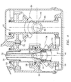
- the first and second angle gear arrangements 40,42 are configured for use with concentric tower shafts 36,38 and side-by-side lay shafts 44,46.
- the first angle gear arrangement 40 includes a ninth bevel gear 72 and a tenth bevel gear 74.
- the ninth bevel gear 72 is attached to the first tower shaft 36.
- the ninth bevel gear 72 is engaged with the tenth bevel gear 74, which is fixed to the first lay shaft 44.
- the second gear arrangement 42 includes a first spur gear 76, a second spur gear 78, an intermediate shaft 80, an eleventh bevel gear 82, and a twelfth bevel gear 84.
- the first spur gear 76 is fixed (e.g., by one or more splines) to the second tower shaft 38.
- the second spur gear 78 and the eleventh bevel gear 82 are attached to the intermediate shaft 80.
- the second spur gear 78 is aligned and engaged with the first spur gear 76.
- the eleventh bevel gear 82 is engaged with the twelfth bevel gear 84, which is fixed to the second lay shaft 46.
- first and second lay shafts 44,46 are disposed side-by-side, rotatable about lengthwise extending parallel axes 86,88.
- the first and second lay shafts 44,46 are shown in phantom in FIG.4, extending out of the page.
- the lay shafts 44,46 are shown extending lengthwise within the page, in the sectional top view of FIG.5.
- the lay shafts 44,46 each include one or more bearing mounts 90 to positionally locate and to facilitate rotation of the respective lay shaft 44,46.
- a coupling (not shown) is attached to, or formed with, the other end of each lay shaft 44,46, for connecting the respective lay shaft to the accessory gearbox 24.
- rotation of the low-pressure drive shaft 14 rotationally drives the LPDS gear arrangement 32.
- the LPDS gear arrangement 32 drives the second tower shaft 38 about its axis 56.
- Rotation of the high-pressure drive shaft 12 rotationally drives the HPDS gear arrangement 34.
- the HPDS gear arrangement 34 drives the first tower shaft 36 about its axis 56.
- rotation of the first tower shaft 36 causes the first angle gear arrangement 40 to rotate and drive the first lay shaft 44 (disposed radially inside of the second lay shaft 46).
- Rotation of the second tower shaft 38 causes the second angle gear arrangement 42 to rotate and drive the second lay shaft 46 (disposed radially outside of the first lay shaft 44).
- the concentric lay shafts 44,46 in turn, drive the accessory gearbox 24.
Landscapes
- Engineering & Computer Science (AREA)
- Chemical & Material Sciences (AREA)
- Combustion & Propulsion (AREA)
- Mechanical Engineering (AREA)
- General Engineering & Computer Science (AREA)
- Gear Transmission (AREA)
Applications Claiming Priority (2)
| Application Number | Priority Date | Filing Date | Title |
|---|---|---|---|
| US10/785,502 US7386983B2 (en) | 2004-02-25 | 2004-02-25 | Apparatus for driving an accessory gearbox in a gas turbine engine |
| US785502 | 2004-02-25 |
Publications (2)
| Publication Number | Publication Date |
|---|---|
| EP1574688A1 true EP1574688A1 (de) | 2005-09-14 |
| EP1574688B1 EP1574688B1 (de) | 2008-09-24 |
Family
ID=34827566
Family Applications (1)
| Application Number | Title | Priority Date | Filing Date |
|---|---|---|---|
| EP05251096A Expired - Lifetime EP1574688B1 (de) | 2004-02-25 | 2005-02-24 | Mechanisches Antriebssystem für ein Hilfsaggregats-Getriebe |
Country Status (4)
| Country | Link |
|---|---|
| US (1) | US7386983B2 (de) |
| EP (1) | EP1574688B1 (de) |
| JP (1) | JP2005240800A (de) |
| DE (1) | DE602005009879D1 (de) |
Cited By (5)
| Publication number | Priority date | Publication date | Assignee | Title |
|---|---|---|---|---|
| FR2882096A1 (fr) * | 2005-02-11 | 2006-08-18 | Snecma Moteurs Sa | Turbomoteur a double corps avec des moyens de prise de mouvement sur les rotors basse pression et haute pression, module de prise de mouvement pour le turbomoteur et procede de montage du turbomoteur |
| FR2921423A1 (fr) * | 2007-09-25 | 2009-03-27 | Snecma Sa | Turbomachine a double corps, avec double prelevement de puissance |
| EP1908941A3 (de) * | 2006-09-27 | 2011-07-27 | General Electric Company | Gasturbinenmotormontage und Montageverfahren dafür |
| WO2012175884A1 (fr) * | 2011-06-24 | 2012-12-27 | Snecma | Relais d'accessoires a duree de vie amelioree |
| EP3696392A1 (de) * | 2019-02-13 | 2020-08-19 | United Technologies Corporation | Winkelhilfsgetriebe für ein gasturbinentriebwerk |
Families Citing this family (36)
| Publication number | Priority date | Publication date | Assignee | Title |
|---|---|---|---|---|
| FR2892455B1 (fr) * | 2005-10-21 | 2008-01-04 | Hispano Suiza Sa | Dispositif d'entrainement de machines auxiliaires d'un turbomoteur a double corps |
| FR2892456B1 (fr) * | 2005-10-21 | 2008-01-04 | Hispano Suiza Sa | Dispositif d'entrainement de machines accessoires d'un moteur a turbine a gaz |
| FR2901315B1 (fr) * | 2006-05-19 | 2010-09-10 | Hispano Suiza Sa | Boitier d'accessoires dans un moteur d'avion tel qu'un turboreacteur |
| US8672606B2 (en) * | 2006-06-30 | 2014-03-18 | Solar Turbines Inc. | Gas turbine engine and system for servicing a gas turbine engine |
| US20080187431A1 (en) * | 2006-06-30 | 2008-08-07 | Ian Trevor Brown | Power system |
| US8590151B2 (en) * | 2006-06-30 | 2013-11-26 | Solar Turbines Inc. | System for supporting and servicing a gas turbine engine |
| US7788898B2 (en) * | 2006-12-06 | 2010-09-07 | General Electric Company | Variable coupling of turbofan engine spools via open differential gear set or simple planetary gear set for improved power extraction and engine operability, with torque coupling for added flexibility |
| WO2008082334A1 (en) * | 2006-12-29 | 2008-07-10 | Volvo Aero Corporation | A gas turbine engine, an aircraft provided therewith, and a method of controlling the operation of such an engine |
| US9719428B2 (en) * | 2007-11-30 | 2017-08-01 | United Technologies Corporation | Gas turbine engine with pylon mounted accessory drive |
| US20090188334A1 (en) * | 2008-01-25 | 2009-07-30 | United Technologies Corp. | Accessory Gearboxes and Related Gas Turbine Engine Systems |
| US20090205341A1 (en) * | 2008-02-20 | 2009-08-20 | Muldoon Marc J | Gas turbine engine with twin towershaft accessory gearbox |
| US8480527B2 (en) * | 2008-08-27 | 2013-07-09 | Rolls-Royce Corporation | Gearing arrangement |
| FR2942273B1 (fr) * | 2009-02-18 | 2011-06-10 | Snecma | Moteur double flux a roues de turbine contrarotatives |
| US9816441B2 (en) * | 2009-03-30 | 2017-11-14 | United Technologies Corporation | Gas turbine engine with stacked accessory components |
| US8572974B2 (en) * | 2009-07-31 | 2013-11-05 | Hamilton Sundstrand Corporation | Variable speed and displacement electric fluid delivery system for a gas turbine engine |
| EP2696058B1 (de) | 2011-04-07 | 2017-10-11 | Kawasaki Jukogyo Kabushiki Kaisha | Flugzeug mit einer Generatorvorrichtung |
| US8814502B2 (en) | 2011-05-31 | 2014-08-26 | Pratt & Whitney Canada Corp. | Dual input drive AGB for gas turbine engines |
| US9068515B2 (en) | 2011-12-07 | 2015-06-30 | United Technologies Corporation | Accessory gearbox with tower shaft removal capability |
| US20130180262A1 (en) * | 2012-01-18 | 2013-07-18 | Hung Duong | Gas turbine engine accessory gearbox |
| US8973465B2 (en) | 2012-07-20 | 2015-03-10 | United Technologies Corporation | Gearbox for gas turbine engine |
| US9297314B2 (en) | 2012-12-19 | 2016-03-29 | United Technologies Corporation | Gas turbine engine with accessory gear box |
| WO2014120134A1 (en) | 2013-01-30 | 2014-08-07 | United Technologies Corporation | Gas turbine engine accessory gearbox |
| ITTO20130636A1 (it) * | 2013-07-29 | 2015-01-30 | Avio Spa | Scatola di trasmissione, e metodo di smontaggio per disaccoppiare un albero di azionamento in tale scatola di trasmissione |
| US10197150B2 (en) | 2015-11-23 | 2019-02-05 | United Technologies Corporation | Gear baffle configured with lubricant outlet passage |
| US10221937B2 (en) | 2016-04-05 | 2019-03-05 | United Technologies Corporation | Slotted oil baffle for gears |
| US10364880B2 (en) | 2017-01-05 | 2019-07-30 | United Technologies Corporation | Oil quieting direction control baffle |
| US10655679B2 (en) | 2017-04-07 | 2020-05-19 | United Technologies Corporation | Oil control for seal plates |
| US10677159B2 (en) | 2017-10-27 | 2020-06-09 | General Electric Company | Gas turbine engine including a dual-speed split compressor |
| US10823081B2 (en) | 2017-12-21 | 2020-11-03 | Raytheon Technologies Corporation | Concentric power takeoff transmission |
| US10920671B2 (en) | 2018-09-25 | 2021-02-16 | Raytheon Technologies Corporation | Thrust balance control with differential power extraction |
| GB2610568A (en) | 2021-09-08 | 2023-03-15 | Rolls Royce Plc | An improved gas turbine engine |
| GB2610569A (en) | 2021-09-08 | 2023-03-15 | Rolls Royce Plc | An improved gas turbine engine |
| GB2610571A (en) | 2021-09-08 | 2023-03-15 | Rolls Royce Plc | An improved gas turbine engine |
| GB2610567A (en) | 2021-09-08 | 2023-03-15 | Rolls Royce Plc | An improved gas turbine engine |
| GB2610565A (en) | 2021-09-08 | 2023-03-15 | Rolls Royce Plc | An improved gas turbine engine |
| GB2610572A (en) * | 2021-09-08 | 2023-03-15 | Rolls Royce Plc | An improved gas turbine engine |
Citations (5)
| Publication number | Priority date | Publication date | Assignee | Title |
|---|---|---|---|---|
| GB839961A (en) * | 1956-11-01 | 1960-06-29 | Bristol Siddeley Engines Ltd | Improvements in or relating to engine accessory mounting arrangements |
| GB1055118A (en) * | 1965-08-19 | 1967-01-18 | Rolls Royce | Gas turbine engine accessory drive mechanism |
| US3543588A (en) * | 1968-11-12 | 1970-12-01 | Gen Motors Corp | Accessory installation |
| US4776163A (en) * | 1986-07-01 | 1988-10-11 | Kloeckner-Humboldt-Deutz Ag | Gas turbine power unit |
| US5694765A (en) * | 1993-07-06 | 1997-12-09 | Rolls-Royce Plc | Shaft power transfer in gas turbine engines with machines operable as generators or motors |
Family Cites Families (4)
| Publication number | Priority date | Publication date | Assignee | Title |
|---|---|---|---|---|
| US2952973A (en) * | 1958-06-02 | 1960-09-20 | Gen Motors Corp | Turbofan-ramjet engine |
| US4525995A (en) * | 1983-04-04 | 1985-07-02 | Williams International Corporation | Oil scavening system for gas turbine engine |
| US5309708A (en) * | 1988-06-03 | 1994-05-10 | Alliedsignal Inc. | Multifunction integrated power unit |
| US20050183540A1 (en) * | 2004-02-25 | 2005-08-25 | Miller Guy W. | Apparatus for driving an accessory gearbox in a gas turbine engine |
-
2004
- 2004-02-25 US US10/785,502 patent/US7386983B2/en active Active
-
2005
- 2005-02-01 JP JP2005024659A patent/JP2005240800A/ja active Pending
- 2005-02-24 DE DE602005009879T patent/DE602005009879D1/de not_active Expired - Lifetime
- 2005-02-24 EP EP05251096A patent/EP1574688B1/de not_active Expired - Lifetime
Patent Citations (5)
| Publication number | Priority date | Publication date | Assignee | Title |
|---|---|---|---|---|
| GB839961A (en) * | 1956-11-01 | 1960-06-29 | Bristol Siddeley Engines Ltd | Improvements in or relating to engine accessory mounting arrangements |
| GB1055118A (en) * | 1965-08-19 | 1967-01-18 | Rolls Royce | Gas turbine engine accessory drive mechanism |
| US3543588A (en) * | 1968-11-12 | 1970-12-01 | Gen Motors Corp | Accessory installation |
| US4776163A (en) * | 1986-07-01 | 1988-10-11 | Kloeckner-Humboldt-Deutz Ag | Gas turbine power unit |
| US5694765A (en) * | 1993-07-06 | 1997-12-09 | Rolls-Royce Plc | Shaft power transfer in gas turbine engines with machines operable as generators or motors |
Cited By (10)
| Publication number | Priority date | Publication date | Assignee | Title |
|---|---|---|---|---|
| FR2882096A1 (fr) * | 2005-02-11 | 2006-08-18 | Snecma Moteurs Sa | Turbomoteur a double corps avec des moyens de prise de mouvement sur les rotors basse pression et haute pression, module de prise de mouvement pour le turbomoteur et procede de montage du turbomoteur |
| EP1701019A1 (de) * | 2005-02-11 | 2006-09-13 | Snecma | Zweiwellenturbomaschine mit Antriebsmodul auf Niederdruck- und Hochdruckrotoren, Antriebsmodul für die Turbomaschine und Montageverfahren der Turbomaschine |
| US7552591B2 (en) | 2005-02-11 | 2009-06-30 | Snecma | Twin spool turbine engine with power take-off means on the low-pressure and high-pressure rotors, and power take-off module for the turbine engine |
| EP1908941A3 (de) * | 2006-09-27 | 2011-07-27 | General Electric Company | Gasturbinenmotormontage und Montageverfahren dafür |
| FR2921423A1 (fr) * | 2007-09-25 | 2009-03-27 | Snecma Sa | Turbomachine a double corps, avec double prelevement de puissance |
| WO2012175884A1 (fr) * | 2011-06-24 | 2012-12-27 | Snecma | Relais d'accessoires a duree de vie amelioree |
| FR2976976A1 (fr) * | 2011-06-24 | 2012-12-28 | Snecma | Relais d'accessoires a duree de vie amelioree |
| US9352649B2 (en) | 2011-06-24 | 2016-05-31 | Snecma | Accessory relay having an extended service life |
| EP3696392A1 (de) * | 2019-02-13 | 2020-08-19 | United Technologies Corporation | Winkelhilfsgetriebe für ein gasturbinentriebwerk |
| EP3696392B1 (de) | 2019-02-13 | 2022-04-20 | Raytheon Technologies Corporation | Winkelhilfsgetriebe für ein gasturbinentriebwerk |
Also Published As
| Publication number | Publication date |
|---|---|
| DE602005009879D1 (de) | 2008-11-06 |
| US20050183529A1 (en) | 2005-08-25 |
| EP1574688B1 (de) | 2008-09-24 |
| US7386983B2 (en) | 2008-06-17 |
| JP2005240800A (ja) | 2005-09-08 |
Similar Documents
| Publication | Publication Date | Title |
|---|---|---|
| US7386983B2 (en) | Apparatus for driving an accessory gearbox in a gas turbine engine | |
| EP1574686B1 (de) | Mechanisches Antriebssystem für ein Hilfsaggregatsgetriebe | |
| EP1574687A1 (de) | Mechanisches Antriebssystem für ein Hilfsaggregatsgetriebe | |
| US11041443B2 (en) | Multi-spool gas turbine engine architecture | |
| US10458340B2 (en) | Turbine shaft power take-off | |
| US8814502B2 (en) | Dual input drive AGB for gas turbine engines | |
| EP3321488B1 (de) | Zubehöranordnung für gasturbinenmotor | |
| EP3273033B1 (de) | Turbinenwellenleistungsabzapfvorrichtung | |
| CN103225548B (zh) | 用于轴向附件齿轮箱的锥齿轮布置结构 | |
| US20180073429A1 (en) | Reverse flow gas turbine engine with offset rgb | |
| CN1840878A (zh) | 双轴涡轮发动机、其动力输出模块和装配该发动机的方法 | |
| US11326523B2 (en) | Gas turbine engine with accessory gearbox | |
| WO2014052269A1 (en) | Off-take power ratio | |
| US20160333793A1 (en) | Accessory gearbox assembly for an aircraft turbine engine | |
| EP3561263B1 (de) | Getriebeanordnung für koaxiale wellen in einem gasturbinentriebwerk |
Legal Events
| Date | Code | Title | Description |
|---|---|---|---|
| PUAI | Public reference made under article 153(3) epc to a published international application that has entered the european phase |
Free format text: ORIGINAL CODE: 0009012 |
|
| AK | Designated contracting states |
Kind code of ref document: A1 Designated state(s): AT BE BG CH CY CZ DE DK EE ES FI FR GB GR HU IE IS IT LI LT LU MC NL PL PT RO SE SI SK TR |
|
| AX | Request for extension of the european patent |
Extension state: AL BA HR LV MK YU |
|
| 17P | Request for examination filed |
Effective date: 20050810 |
|
| AKX | Designation fees paid |
Designated state(s): DE FR GB |
|
| GRAP | Despatch of communication of intention to grant a patent |
Free format text: ORIGINAL CODE: EPIDOSNIGR1 |
|
| GRAS | Grant fee paid |
Free format text: ORIGINAL CODE: EPIDOSNIGR3 |
|
| GRAA | (expected) grant |
Free format text: ORIGINAL CODE: 0009210 |
|
| AK | Designated contracting states |
Kind code of ref document: B1 Designated state(s): DE FR GB |
|
| REG | Reference to a national code |
Ref country code: GB Ref legal event code: FG4D |
|
| REF | Corresponds to: |
Ref document number: 602005009879 Country of ref document: DE Date of ref document: 20081106 Kind code of ref document: P |
|
| PLBE | No opposition filed within time limit |
Free format text: ORIGINAL CODE: 0009261 |
|
| STAA | Information on the status of an ep patent application or granted ep patent |
Free format text: STATUS: NO OPPOSITION FILED WITHIN TIME LIMIT |
|
| 26N | No opposition filed |
Effective date: 20090625 |
|
| PGFP | Annual fee paid to national office [announced via postgrant information from national office to epo] |
Ref country code: FR Payment date: 20100223 Year of fee payment: 6 |
|
| REG | Reference to a national code |
Ref country code: FR Ref legal event code: ST Effective date: 20111102 |
|
| PG25 | Lapsed in a contracting state [announced via postgrant information from national office to epo] |
Ref country code: FR Free format text: LAPSE BECAUSE OF NON-PAYMENT OF DUE FEES Effective date: 20110228 |
|
| PGFP | Annual fee paid to national office [announced via postgrant information from national office to epo] |
Ref country code: DE Payment date: 20130220 Year of fee payment: 9 Ref country code: GB Payment date: 20130220 Year of fee payment: 9 |
|
| REG | Reference to a national code |
Ref country code: DE Ref legal event code: R119 Ref document number: 602005009879 Country of ref document: DE |
|
| GBPC | Gb: european patent ceased through non-payment of renewal fee |
Effective date: 20140224 |
|
| REG | Reference to a national code |
Ref country code: DE Ref legal event code: R119 Ref document number: 602005009879 Country of ref document: DE Effective date: 20140902 |
|
| PG25 | Lapsed in a contracting state [announced via postgrant information from national office to epo] |
Ref country code: GB Free format text: LAPSE BECAUSE OF NON-PAYMENT OF DUE FEES Effective date: 20140224 Ref country code: DE Free format text: LAPSE BECAUSE OF NON-PAYMENT OF DUE FEES Effective date: 20140902 |