EP1574745B2 - Torsionsschwingungsdämpfer - Google Patents
Torsionsschwingungsdämpfer Download PDFInfo
- Publication number
- EP1574745B2 EP1574745B2 EP05005229A EP05005229A EP1574745B2 EP 1574745 B2 EP1574745 B2 EP 1574745B2 EP 05005229 A EP05005229 A EP 05005229A EP 05005229 A EP05005229 A EP 05005229A EP 1574745 B2 EP1574745 B2 EP 1574745B2
- Authority
- EP
- European Patent Office
- Prior art keywords
- friction
- transmission element
- torsional vibration
- vibration damper
- clutch
- Prior art date
- Legal status (The legal status is an assumption and is not a legal conclusion. Google has not performed a legal analysis and makes no representation as to the accuracy of the status listed.)
- Expired - Lifetime
Links
- 230000005540 biological transmission Effects 0.000 claims abstract description 25
- 229910000831 Steel Inorganic materials 0.000 claims abstract description 19
- 239000010959 steel Substances 0.000 claims abstract description 19
- 238000000034 method Methods 0.000 claims abstract description 13
- 238000004080 punching Methods 0.000 claims abstract description 7
- 238000013016 damping Methods 0.000 claims description 2
- 238000004519 manufacturing process Methods 0.000 description 7
- 239000004519 grease Substances 0.000 description 4
- 238000003754 machining Methods 0.000 description 4
- 238000000926 separation method Methods 0.000 description 4
- 239000000835 fiber Substances 0.000 description 3
- 239000000463 material Substances 0.000 description 3
- 238000007789 sealing Methods 0.000 description 3
- XAGFODPZIPBFFR-UHFFFAOYSA-N aluminium Chemical compound [Al] XAGFODPZIPBFFR-UHFFFAOYSA-N 0.000 description 2
- 229910052782 aluminium Inorganic materials 0.000 description 2
- 238000005096 rolling process Methods 0.000 description 2
- 239000007858 starting material Substances 0.000 description 2
- 238000013459 approach Methods 0.000 description 1
- 230000015572 biosynthetic process Effects 0.000 description 1
- 238000005266 casting Methods 0.000 description 1
- 238000002485 combustion reaction Methods 0.000 description 1
- 238000005520 cutting process Methods 0.000 description 1
- 230000007423 decrease Effects 0.000 description 1
- 210000003746 feather Anatomy 0.000 description 1
- 238000007373 indentation Methods 0.000 description 1
- 230000002093 peripheral effect Effects 0.000 description 1
- 238000012805 post-processing Methods 0.000 description 1
- 238000011084 recovery Methods 0.000 description 1
Images


Classifications
-
- F—MECHANICAL ENGINEERING; LIGHTING; HEATING; WEAPONS; BLASTING
- F16—ENGINEERING ELEMENTS AND UNITS; GENERAL MEASURES FOR PRODUCING AND MAINTAINING EFFECTIVE FUNCTIONING OF MACHINES OR INSTALLATIONS; THERMAL INSULATION IN GENERAL
- F16F—SPRINGS; SHOCK-ABSORBERS; MEANS FOR DAMPING VIBRATION
- F16F15/00—Suppression of vibrations in systems; Means or arrangements for avoiding or reducing out-of-balance forces, e.g. due to motion
- F16F15/10—Suppression of vibrations in rotating systems by making use of members moving with the system
- F16F15/12—Suppression of vibrations in rotating systems by making use of members moving with the system using elastic members or friction-damping members, e.g. between a rotating shaft and a gyratory mass mounted thereon
- F16F15/131—Suppression of vibrations in rotating systems by making use of members moving with the system using elastic members or friction-damping members, e.g. between a rotating shaft and a gyratory mass mounted thereon the rotating system comprising two or more gyratory masses
- F16F15/13142—Suppression of vibrations in rotating systems by making use of members moving with the system using elastic members or friction-damping members, e.g. between a rotating shaft and a gyratory mass mounted thereon the rotating system comprising two or more gyratory masses characterised by the method of assembly, production or treatment
Definitions
- the present invention relates to a torsional vibration damper according to the preamble of claim 1.
- a torsional vibration damper which has a drive-side transmission element and a relation to the same HFausschbares output-side transmission element.
- the latter is designed in several parts and, in addition to a centering of the output-side transmission element relative to the drive-side transmission element causing hub disc and a flywheel element attached thereto, via which a friction clutch can be added.
- Such friction clutches contain a clutch disc in the usual way, which is formed on both sides with friction linings, of which the flywheel mass element adjacent friction lining can be brought to a designated friction surface of the flywheel element in abutment.
- the flywheel element itself consists in the known arrangement of sheet steel and is characterized in relation to otherwise conventional castings excellently deformable. However, there is also the problem of unsatisfactory surface quality even with existing flywheel elements made of sheet steel.
- the DE-A-1 425 358 discloses a hydrodynamic torque converter with a lock-up clutch provided in the housing.
- This lock-up clutch comprises a spring-biased clutch piston, which has a first friction surface for the friction linings of a clutch disc of the lock-up clutch.
- An abutment element rotatably coupled to the turbine wheel and via this with an output shaft provides a second friction surface for the friction linings of the clutch disk.
- This second friction surface is formed in the region of a depression in the abutment element, which is shaped in this way; that in the case of an axially unloaded clutch disk, the distance between the friction surface and the associated friction lining of the clutch disk decreases from radially outside to radially inside.
- the invention has the object of providing a component of a torsional vibration damper, in particular a flywheel element, in such a way that it can be produced with inquiriesstmögiichem manufacturing and cost.
- a steel sheet as the starting point for a flywheel element of the driven side transmission element is resorted to a base material, the surface formed by a rolling skin already convinced with a surface finish, especially in terms of flat and smooth surface, which makes reworking the flywheel element dispensable, especially in places in which a connection with other components is to be produced, such as with a hub disc of the output-side transmission element or with a friction clutch, or an operative connection, as with the respective adjacent friction lining of a clutch disc of the friction clutch.
- Commercially available steel sheet panels in addition to their high surface quality, also have a substantially uniform thickness.
- the substantially annular flywheel element arises as a separation, in particular as a stamped part, from the sheet steel panel.
- the flywheel mass element in this punching process may also be subjected to a simultaneous or subsequent forming process in order to produce a possibly desired profiling.
- a simultaneous or subsequent forming process is a cost-effective manufacturing process, in addition to geometric requirements of the flywheel element and a stiffening of the same and the generation of better functionality and a higher surface quality can bring about.
- the functionality is increased by concave formation of a friction surface of the flywheel element by this is designed for attachment of the adjacent friction lining of the clutch disc in cross section with a slightly concave design, the achieved by the concave axial recovery of the flywheel element on the friction surface in the order of 0, 05 mm to 0.5 mm.
- the friction radius initially effective during the engagement process ie when the friction lining of the clutch disk approaches the friction surface of the flywheel element, is displaceable radially outwards and thereby increases the torque transmission capability of the friction clutch.
- a torsional vibration damper rotatable about a rotation axis 85 is shown, which is accommodated on a drive 1, such as, for example, a crankshaft 3 of an internal combustion engine.
- a drive 1 such as, for example, a crankshaft 3 of an internal combustion engine.
- the crankshaft 3 at its free end to a flange 4 which is formed with threaded holes 5 which are provided for receiving fastening means 7 in the form of screws 9, the shaft is inserted into each of the threaded holes 5.
- the shank of each screw 9 also passes through passages of a substantially radially outwardly extending primary flange 15, which is part of a drive-side transmission element 36, and a contact washer 17, which is clamped axially between the head of the screw 9 and the primary flange 15.
- the primary flange 15 has radially inside a primary hub 19, which extends in a direction away from the crankshaft 3 direction.
- a Lagerausdrückung 20 which receives a planetary gear 23 of a planetary gear 25 rotatably.
- the primary flange 15 merges into a substantially axially extending annular wall 27, which radially outwardly carries a ring gear 29, which can be brought into rotary connection with a starter pinion, not shown.
- This annular wall 27 serves to receive a radially inwardly running sealing wall 33 which, together with the annular wall 27 and the primary flange 15 encloses a grease chamber 35 which is at least partially filled with viscous medium and part of the drive-side transmission element 36.
- a radially inwardly running sealing wall 33 which, together with the annular wall 27 and the primary flange 15 encloses a grease chamber 35 which is at least partially filled with viscous medium and part of the drive-side transmission element 36.
- an axial indentation 37 is provided on the sealing wall 33, which except for gap width at the associated.
- Area of a hub disc 39 is introduced, which has a directed toward the crankshaft 3 Seismeamabe 41 in the radially inner region.
- a radial bearing 43 is provided, which is formed in the present case as a slide bearing.
- the hub disc 39 is formed with a through hole 44 for the passage of the fastening means 7.
- the axial distance of the hub disc 39 is adjusted relative to the primary flange 15 via an axial bearing 31, which is held axially between the contact plate 17 and the hub disc 39.
- output-side drive elements 77 of a damping device 79 provided with springs 83 are integrally formed.
- a corresponding drive-side drive element 81 is attached to the primary flange 15 and another to the seal wall 33, in each case on the grease chamber side of the corresponding element.
- Fig. 2 shows a drawing of the output-side transmission element 53, consisting of the hub disc 39 and the flywheel element 51.
- the latter should be made of an optimally urnformbaren sheet steel, such as STW 24 or Consist of aluminum sheet.
- a first connection surface 94 is provided on the side of the flywheel element 51 facing the hub disk 39, while second connection surfaces 96 are provided at the point of the flywheel element 51 which serves to receive the clutch housing 57 of the friction clutch 55. while the other location of the second connection surface 96 is provided in the radial extension region of a friction surface 98 for the adjacent friction lining 67 of the clutch disc 63.
- a steel sheet panel 90 is used as the starting material for the production of the flywheel element 51, which already ex works can be provided with a comparatively high surface quality.
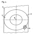
- Such sheet steel panels 90 moreover, being manufactured by a rolling process, have an aligned fiber path 118 through an opened material window X in FIG Fig. 4 should be brought to the presentation. Typically, this fiber profile is constructed with substantially parallel aligned fibers.
- FIG. 4 shows the flywheel element 51 as a separation 92 from the steel sheet panel 90, wherein the separation 92 can be carried out by means of a punching process.
- This can be superimposed or connected to a forming process to form on the by means of the punching operation with respect to the steel sheet panel 90 exempted flywheel element 51 a possibly desired profiling.
- Both in the stamping process and in the forming process are relatively inexpensive manufacturing operations, while due to the steel sheet panel 90 already adhering high surface finish costly machining is unnecessary, both the flywheel element 51 as a whole and on the connecting surfaces 94, 96 in particular ,
- FIG. 3 An inventive measure is in Fig. 3 illustrated, after which the friction surface 98 of the flywheel element 51 is provided with a substantially concave retraction 100 relative to the other friction surface 98, starting from a friction surface outer diameter 102.
- the meaning of such a withdrawal 100 in the friction surface 98 therein Not yet fully established friction connection between the friction surface 98 and the adjacent friction lining 67 of the clutch disc 63 to provide a defined Clearstromradius, which is located in the radially outer region of the friction surface 98 and thereby effective as a large friction radius, with a comparatively secure torque transmission through the Friction clutch 55 is guaranteed.
- the return 100 of the friction surface 98 can be produced by means of a forming process and therefore without machining post-processing.
Landscapes
- Engineering & Computer Science (AREA)
- General Engineering & Computer Science (AREA)
- Manufacturing & Machinery (AREA)
- Physics & Mathematics (AREA)
- Acoustics & Sound (AREA)
- Aviation & Aerospace Engineering (AREA)
- Mechanical Engineering (AREA)
- Mechanical Operated Clutches (AREA)
- Surgical Instruments (AREA)
- Buildings Adapted To Withstand Abnormal External Influences (AREA)
- Vibration Prevention Devices (AREA)
- Vibration Dampers (AREA)
Description
- Die vorliegende Erfindung betrifft einen Torsionsschwingungsdämpfer gemäß dem Oberbegriff des Anspruches 1.
- Durch die
DE 100 04 125 A1 ist ein Torsionsschwingungsdämpfer bekannt, der über ein antriebsseitiges Übertragungselement und über ein gegenüber demselben drehauslenkbares abtriebsseitiges Übertragungselement verfügt. Das Letztgenannte ist mehrteilig ausgebildet und weist außer einer eine Zentrierung des abtriebsseitigen Übertragungselementes gegenüber dem antriebsseitigen Übertragungselement bewirkenden Nabenscheibe auch ein daran befestigtes Schwungmassenelement auf, über welches eine Reibungskupplung aufgenommen werden kann. Derartige Reibungskupplungen enthalten in üblicher Weise eine Kupplungsscheibe, die beidseits mit Reibbelägen ausgebildet ist, von denen der dem Schwungmassenelement benachbarte Reibbelag an einer hierfür vorgesehenen Reibfläche des Schwungmassenelementes in Anlage bringbar ist. - Das Schwungmassenelement selbst besteht bei der bekannten Anordnung aus Stahlblech und ist dadurch gegenüber ansonsten üblichen Gussausführungen vorzüglich umformbar. Allerdings besteht auch bei aus Stahlblech bestehenden Schwungmassenelementen das Problem einer unbefriedigenden Oberflächengüte.
- Dem kann zwar durch Nachbearbeitung, insbesondere an den Verbindungsflächen zur Nabenscheibe einerseits und zur Reibungskupplung sowie zur Reibfläche für den Reibbelag der Kupplungsscheibe andererseits abgeholfen werden, jedoch handelt es sich bei derartigen Nachbearbeitungen im Wesentlichen um spanabhebende Fertigungsvorgänge, die eine beträchtliche Mehrbelastung an Kosten für die Herstellung des Schwungmassenelementes verursachen.
- Die
DE-A-1 425 358 offenbart einen hydrodynamischen Drehmomentwandler mit einer in dessen Gehäuse vorgesehenen Überbrückungskupplung. Diese Überbrückungskupplung umfasst einen unter Federvorspannung stehenden Kupplungskolben, welcher eine erste Reibfläche für die Reibbeläge einer Kupplungsscheibe der Überbrückungskupplung aufweist. Ein mit dem Turbinenrad und über dieses mit einer Abtriebswelle drehfest gekoppeltes Widerlagerelement stellt eine zweite Reibfläche bereit für die Reibbeläge der Kupplungsscheibe. Diese zweite Reibfläche ist im Bereich einer Einsenkung im Widerlagerelement gebildet, welche so geformt ist; dass bei axial unbelasteter Kupplungsscheibe der Abstand der Reibfläche zum zugeordneten Reibbelag der Kupplungsscheibe von radial außen nach radial innen abnimmt. - Der Erfindung liegt die Aufgabe zugrunde, ein Bauteil eines Torsionsschwingungsdämpfers, insbesondere ein Schwungmassenelement, so auszubilden, dass dieses mit geringstmögiichem Fertigungs- und Kostenaufwand herstellbar ist.
- Diese Aufgabe wird durch einen Torsionsschwingungsdämpfer gemäß Anspruch 1 gelöst.
- Durch Verwendung einer Stahlblechtafel als Ausgangsbasis für ein Schwungmassenelement des abtriebsseitigen Übertragungselementes wird auf ein Grundmaterial zurückgegriffen, dessen durch eine Walzhaut gebildete Oberfläche bereits mit einer Oberflächengüte, insbesondere im Hinblick auf Eben- und Glattflächigkeit überzeugt, die eine Nachbearbeitung des Schwungmassenelements entbehrlich macht, insbesondere an Stellen, an denen eine Verbindung mit anderen Bauteilen herzustellen ist, wie mit einer Nabenscheibe des abtriebsseitigen Übertragungselementes oder mit einer Reibungskupplung, oder aber eine Wirkverbindung, wie mit dem jeweils benachbarten Reibbelag einer Kupplungsscheibe der Reibungskupplung. Handelsübliche Stahlblechtafeln verfügen neben ihrer hohen Oberflächengüte auch über eine im Wesentlichen gleichmäßige Dicke. Zugunsten guter Umformbarkeit sind hierbei insbesondere Stahlblechtafeln aus einem Werkstoff mit vorzüglichen Umformungseigenschaften, wie STW 24, QSTE oder Aluminium, zu verwenden. Durch Verzicht insbesondere auf spanabhebende Nachbearbeitungsvorgänge besteht die Möglichkeit einer erheblichen fertigungstechnischen Vereinfachung und damit einer deutlichen Kostenreduzierung gegenüber einer Gussausführung des Schwungmassenelements.
- Das im Wesentlichen ringförmige Schwungmassenelement entsteht als Heraustrennung, insbesondere als Stanzteil, aus der Stahlblechtafel. Gegebenenfalls kann das Schwungmassenelement bei diesem Stanzvorgang auch einem gleichzeitigen oder anschließenden Umformvorgang unterworfen sein, um eine eventuell gewünschte Profilierung zu erzeugen. Bei einem derartigen Umformvorgang handelt es sich um einen kostengünstigen Fertigungsvorgang, der neben geometrischen Erfordernissen des Schwungmassenelements auch eine Versteifung derselben sowie die Erzeugung einer besseren Funktionalität sowie eine nochmals höhere Oberflächengüte herbeiführen kann.
- Die Funktionalität ist durch konkave Ausbildung einer Reibfläche des Schwungmassenelementes erhöht, indem diese zur Anlagerung des benachbarten Reibbelages der Kupplungsscheibe im Querschnitt mit leicht konkaver Ausbildung gestaltet ist, wobei die durch die konkave Ausbildung erzielte axiale Rücknahme des Schwungmassenelementes an der Reibfläche in der Größenordnung von 0,05 mm bis 0,5 mm liegen kann. Aufgrund dieser Umformung am Schwungmassenelement ist der beim Einrückvorgang, also bei axialer Annäherung des Reibbelages der Kupplungsscheibe an die Reibfläche des Schwungmassenelementes, zunächst wirksame Reibradius nach radial außen verlagerbar und vergrößert dadurch die Drehmomentübertragungsfähigkeit der Reibungskupplung.
- Im Folgenden wird ein bevorzugtes Ausführungsbeispiel der Erfindung anhand der beiliegenden Figuren erläutert. Es zeigt:
- Fig. 1
- einen Torsionsschwingungsdämpfer mit einem antriebsseitigen Übertragungselement und einem eine Reibungskupplung aufnehmenden, abtriebsseitigen Übertragungselement;
- Fig. 2
- eine Herauszeichnung des abtriebsseitigen Übertragungselementes, aufweisend eine Nabenscheibe und ein damit verbundenes Schwungmassenelement;
- Fig. 3
- eine Herauszeichnung des Schwungmassenelementes in nochmals vergrößerter Darstellung mit einer konkaven axialen Rücknahme im Bereich einer Reibfläche des Schwungmassenelementes;
- Fig. 4
- das Schwungmassenelement vor einem Herausstanzen aus einer Stahlblechtafel.
- In
Fig. 1 ist ein um eine Drehachse 85 drehbarer Torsionsschwingungsdämpfer dargestellt, der an einem Antrieb 1, wie beispielsweise einer Kurbelwelle 3 einer Brennkraftmaschine aufgenommen ist. Hierzu weist die Kurbelwelle 3 an ihrem freien Ende einen Flansch 4 auf, der mit Gewindebohrungen 5 ausgebildet ist, die zur Aufnahme von Befestigungsmitteln 7 in Form von Schrauben 9 vorgesehen sind, deren Schaft jeweils in eine der Gewindebohrungen 5 einführbar ist. Der Schaft jeder Schraube 9 durchgreift weiterhin Durchgänge eines sich im wesentlichen nach radial außen erstreckenden Primärtfansches 15, der Teil eines antriebsseitigen Übertragungselementes 36 ist, sowie einer Anlagescheibe 17, die axial zwischen dem Kopf der Schraube 9 und dem Primärflansch 15 eingespannt ist. Der Primärflansch 15 weist radial innen eine Primärnabe 19 auf, die sich in einer von der Kurbelwelle 3 abgewandten Richtung erstreckt. Im radial mittleren Bereich ist der Primärflansch 15 mit einer Lagerausdrückung 20 versehen, die ein Planetenrad 23 eines Planetengetriebes 25 drehbar aufnimmt. Im radial äußeren Bereich geht der Primärflansch 15 in eine sich im viesentlichen axial erstreckende Ringwand 27 über, die radial außen einen Zahnkranz 29 trägt, der mit einem nicht gezeigten Anlasserritzel in Drehverbindung bringbar ist. Diese Ringwand 27 dient zur Aufnahme einer nach radial innen laufenden Dichtungswand 33, die zusammen mit der Ringwand 27 und dem Primärflansch 15 eine Fettkammer 35 umschließt, die zumindest teilweise mit viskosem Medium befüllt und Teil des antriebsseitigen Übertragungselementes 36 ist. Zur Abdichtung dieser Fettkammer 35 ist an der Dichtungswand 33 eine Axialeindrückung 37 vorgesehen, die bis auf Spaltbreite an den zugeordneten. Bereich einer Nabenscheibe 39 herangeführt ist, die im radial inneren Bereich eine auf die Kurbelwelle 3 zu gerichtete Sekundämabe 41 aufweist. - Radial zwischen der bereits erwähnten Primärnabe 19 des Primärflansches 15 und der Sekundämabe 41 der Nabenscheibe 39 ist eine Radiallagerung 43 vorgesehen, die im vorliegenden Fall als Gleitlagerung ausgebildet ist. Radial außerhalb der Sekundärnabe 41 ist die Nabenscheibe 39 mit einer Durchgangsöffnung 44 zum Durchstecken der Befestigungsmittel 7 ausgebildet. Außerdem wird der Äxialabstand der Nabenscheibe 39 gegenüber dem Primärflansch 15 über eine Axiallagerung 31 eingestellt, die axial zwischen der Anlagescheibe 17 und der Nabenscheibe 39 gehalten ist. Noch weiter radial außen ist eine Vernietung 49 vorgesehen, durch welche eine Verbindung der Nabenscheibe 39 zu einem abtriebsseitigen Schwungmassenelement 51 hergestellt wird, das ebenso wie die Nabenscheibe 39 als abtriebsseitiges Übertragungselement 53 wirksam ist und in an sich bekannter Weise zur Aufnahme einer Reibungskupplung 55 dient, die in einem Kupplungsgehäuse 57 eine Membranfeder 59 und eine Anpressplatte 61 sowie eine durch dieselben beaufschlagbare Kupplungsscheibe 63 mit beidseits eines Trägers 65 derselben aufgenommenen Reibbelägen 67, 69 aufnimmt.
- Zurückkommend auf die Nabenscheibe 39 weist diese radial außerhalb der Vernietung 49 eine Innenverzahnung 73 auf, mit welcher sie in Eingriff mit der Verzahnung des zuvor bereits erwähnten Planetenrades 23 steht. Die Nabenscheibe 39 ist demnach als Hohlrad 75 des Planetengetriebes 25 wirksam.
- Am Umfangsbereich der Nabenscheibe 39 sind abtriebsseitige Ansteuerelemente 77 einer mit Federn 83 versehenen Dämpfungseinrichtung 79 angeformt. Ein entsprechendes antriebsseitiges Ansteuerelement 81 ist am Primärflansch 15 und ein weiteres an der Dichtungswand 33 befestigt, und zwar jeweils an der Fettkammerseite des entsprechenden Elementes.
-
Fig. 2 zeigt eine Herauszeichnung des abtriebsseitigen Übertragungselementes 53, bestehend aus der Nabenscheibe 39 und dem Schwungmassenelement 51. Das Letztgenannte soll aus einem optimal urnformbaren Stahlblech, wie beispielsweise STW 24 oder aus Aluminiumblech bestehen. Zur Anbindung an die Nabenscheibe 39 soll eine erste Verbindungsfläche 94 an der der Nabenscheibe 39 zugewandten Seite des Schwungmassenelementes 51 vorgesehen sein, während zweite Verbindungsflächen 96 zum einen an derjenigen Stelle des Schwungmassenelementes 51 vorgesehen sind, die zur Aufnahme des Kupplungsgehäuses 57 der Reibungskupplung 55 dient, während die andere Stelle der zweiten Verbindungsfläche 96 im radialen Erstreckungsbereich einer Reibfläche 98 für den benachbarten Reibbelag 67 der Kupplungsscheibe 63 vorgesehen ist. - Um zumindest diese Verbindungsflächen 94, 96, besser noch alle Bereiche des Schwungmassenelementes 51, mit der gewünschten Oberflächengüte ausbilden zu können, ohne hierfür eine spanabhebende Nachbearbeitung durchführen zu müssen, wird als Ausgangsmaterial zur Herstellung des Schwungmassenelementes 51 eine Stahlblechtafel 90 verwendet, die bereits ab Werk mit einer vergleichsweise hohen Oberflächengüte bereitgestellt werden kann. Derartige Stahlblechtafeln 90 verfügen zudem, da sie durch ein Walzverfahren hergestellt werden, über einen ausgerichteten Faserverlauf 118, der durch ein geöffnetes Materialfenster X in
Fig. 4 zur Darstellung gebracht werden soll. Üblicherweise ist dieser Faserverlauf mit im Wesentlichen parallel zueinander ausgerichteten Fasern aufgebaut. - Wie
Fig. 4 weiterhin zeigt, entsteht das Schwungmassenelement 51 als Heraustrennung 92 aus der Stahlblechtafel 90, wobei die Heraustrennung 92 mittels eines Stanzvorganges erfolgen kann. Diesem kann ein Umformvorgang überlagert oder angeschlossen sein, um an dem mittels des Stanzvorganges gegenüber der Stahlblechtafel 90 freigestellten Schwungmassenelement 51 eine eventuell gewünschte Profilierung auszubilden. Sowohl bei dem Stanzvorgang als auch bei dem Umformvorgang handelt es sich um vergleichsweise kostengünstige Fertigungsvorgänge, während aufgrund der der Stahlblechtafel 90 bereits zuvor anhaftenden hohen Oberflächengüte eine kostenaufwändige spanabhebende Nachbearbeitung entbehrlich ist, sowohl beim Schwungmassenelement 51 insgesamt als auch an den Verbindungsflächen 94, 96 im Besonderen. - Eine erfindungswesentliche Maßnahme ist in
Fig. 3 zeichnerisch dargestellt, wonach die Reibfläche 98 des Schwungmassenelementes 51 mit einer im Wesentlichen konkav ausgebildeten Rücknahme 100 gegenüber der sonstigen Reibfläche 98 versehen ist, und zwar ausgehend von einem Reibflächen-Außendurchmesser 102. Der Sinn einer derartigen Rücknahme 100 in der Reibfläche 98 liegt darin, bei noch nicht vollständig hergestellter Reibverbindung zwischen der Reibfläche 98 und dem benachbarten Reibbelag 67 der Kupplungsscheibe 63 einen definierten Erstanlageradius bereit zu stellen, der sich im radial äußeren Bereich der Reibfläche 98 befindet und dadurch als großer Reibradius wirksam ist, mit dem eine vergleichsweise sichere Momentenübertragung durch die Reibungskupplung 55 gewährleistet ist. Auch die Rücknahme 100 der Reibfläche 98 kann mittels eines Umformvorganges und daher ohne spanabhebende Nachbearbeitung hergestellt werden. -
- 1.
- Antrieb
- 3.
- Kurbelwelle
- 4.
- Flansch
- 5.
- Gewindebohrungen
- 7.
- Befestigungsmittel
- 9.
- Schrauben
- 15.
- Primärflansch
- 17.
- Anlegescheibe
- 19-
- Primärnabe
- 20.
- Lagerausdrückung
- 23.
- Planetenrad
- 25.
- Plantetengetriebe
- 27.
- Ringwand
- 29.
- Zahnkranz
- 31.
- Axiallagerung
- 33.
- Dichtungswand
- 35.
- Fettkammer
- 36.
- antriebss. Übertragungselement
- 37.
- Axialeindrückung
- 39.
- Nabenscheibe
- 41.
- Sekundärnabe
- 43.
- Radiallagerung
- 44.
- Durchgangsöffnung
- 49.
- Vernietung
- 51.
- Schwungmassenelement
- 53.
- abtriebss. Übertragungselement
- 55.
- Reibungskupplung
- 57.
- Kupplungsgehäuse
- 59.
- Membranfeder
- 61.
- Anpressplatte
- 63.
- Kupplungsscheibe
- 65.
- Träger
- 67,69
- Reibbeläge
- 73.
- Innenverzahnung
- 75.
- Hohlrad
- 77.
- Ansteuerelemente abtriebsseitig
- 79.
- Dämpfungseinrichtung
- 81.
- Ansteuerelemente antriebsseitig
- 83.
- Federn
- 85.
- Mittenachse
- 90.
- Stahlblechtafel
- 92.
- Heraustrennung
- 94,96
- Verbindungsflächen
- 98.
- Reibfläche
- 100.
- Rücknahme
- 102.
- Reibflächen-Außendurchmesser
- 104.
- Rückseite
Claims (4)
- Torsionsschwingungsdämpfer mit einem antriebsseitigen Übertragunselement, das über eine In Umfangsrichtung wirksame Dämpfungseinrichtung (79) mit einem relativ zum antriebsseitigen Übertragungselement (36) drehauslenkbaren abtriebsseitigen Übertragungselement (53) verbunden ist, wobei zumindestdas letztgenannte überein aus einem umformbaren Stahlblech bestehendes Schwungmassenelement (51) verfügt, das über wenigstens eine erste Verbindungsfläche (94) mit einer eine Zentrierung des abtriebsseitigen Übertragungselementes gegenüber dem antriebsseitigen Übertragungselement bewirkenden Nabenscheibe (39) drehfest verbunden ist, und über zumindest eine zweite Verbindungsfläche (96) eine Reibungskupplung (55) aufnimmt sowie eine Reibfläche für einen Reibbelag einer Kupplungsscheibe (63) der Reibungskupplung bereit stellt,
dadurch gekennzeichnet,
dass das Schwungmassenelement (51) als Heraustrennung (92) aus einer Stahlblechtafel (90) gebildet ist und im Wesentlichen über die gleiche Oberflächengüte wie die Stahlblechtafel (90) verfügt, wobei aufgrund dieser Oberflächengüte selbst an den Verbindungsflächen (94, 96) des Schwungmassenelementes (51) Entbehrlichkeit für eine Nachbearbeitung vorliegt, und
dass das Schwungmassenelement (51) an seiner Reibfläche (98) im Querschnitt in im Wesentlichen radialer Erstreckungsrichtung über einen konkaven Verlauf verfügt, wobei dieser eine Rücknahme (100) im radialen Erstreckungsbereich der Reibfläche (98) radial innerhalb des Reibflächen - Außendurchmessers (102) zur Folge hat. - Torsionsschwingungsdämpfer nach Anspruch 1,
dadurch gekennzeichnet,
dass die Heraustrennung (92) des Schwungmassenelementes (51) aus der Stahlblechtafel (90) mittels eines Stanzvorganges herstellbar ist. - Torsionsschwingungsdämpfer nach Anspruch 2,
dadurch gekennzeichnet,
dass die Heraustrennung (92) durch einen mit dem Stanzvorgang kombinierbaren Umformvorgang plastisch verformbar ist. - Torsionsschwingungsdämpfer nach einem der Ansprüche 1-3,
dadurch gekennzeichnet,
dass die Rücknahme (100) an der Reibfläche (98) in der Größenordnung unterhalb von 0,5 mm liegt.
Applications Claiming Priority (2)
| Application Number | Priority Date | Filing Date | Title |
|---|---|---|---|
| DE102004012425A DE102004012425A1 (de) | 2004-03-13 | 2004-03-13 | Torsionsschwingungsdämpfer |
| DE102004012425 | 2004-03-13 |
Publications (3)
| Publication Number | Publication Date |
|---|---|
| EP1574745A1 EP1574745A1 (de) | 2005-09-14 |
| EP1574745B1 EP1574745B1 (de) | 2006-05-03 |
| EP1574745B2 true EP1574745B2 (de) | 2011-11-23 |
Family
ID=34813694
Family Applications (1)
| Application Number | Title | Priority Date | Filing Date |
|---|---|---|---|
| EP05005229A Expired - Lifetime EP1574745B2 (de) | 2004-03-13 | 2005-03-10 | Torsionsschwingungsdämpfer |
Country Status (3)
| Country | Link |
|---|---|
| EP (1) | EP1574745B2 (de) |
| AT (1) | ATE325290T1 (de) |
| DE (2) | DE102004012425A1 (de) |
Families Citing this family (4)
| Publication number | Priority date | Publication date | Assignee | Title |
|---|---|---|---|---|
| BRPI0613431B1 (pt) * | 2005-07-14 | 2018-08-14 | Schaeffler Technologies AG & Co. KG | Equipamento de amortecimento de vibrações, em particular, volante de duas massas |
| DE102008063015A1 (de) * | 2008-12-23 | 2010-07-01 | GAT Gesellschaft für Antriebstechnik mbH | Torsionsschwingungsdämpfer mit einer Primärseite und Verfahren zum Herstellen einer Primärmasse eines Torsionsschwingungsdämpfers |
| CN102343768B (zh) * | 2011-07-14 | 2013-06-12 | 徐工集团工程机械股份有限公司江苏徐州工程机械研究院 | 一种电动轮矿用自卸车车轮布局结构 |
| DE102017213910A1 (de) * | 2017-08-10 | 2019-02-14 | Zf Friedrichshafen Ag | Schwungradanordnung für einen Antriebsstrang eines Fahrzeugs |
Citations (1)
| Publication number | Priority date | Publication date | Assignee | Title |
|---|---|---|---|---|
| US6138806A (en) † | 1997-01-16 | 2000-10-31 | Mannesmann Sachs Ag | Clutch disk with varied friction values |
Family Cites Families (4)
| Publication number | Priority date | Publication date | Assignee | Title |
|---|---|---|---|---|
| DE1425358B2 (de) | 1961-12-12 | 1971-02-18 | Societe Anonyme Francaise Du Ferodo, Paris | Hydraulisch betaetigbare scheibenreibungskupplung |
| GB2266125B (en) * | 1992-04-18 | 1996-08-14 | Luk Lamellen & Kupplungsbau | Torque transfer device |
| DE4340175B4 (de) * | 1992-12-07 | 2013-02-21 | Schaeffler Technologies AG & Co. KG | Einrichtung zum Kompensieren von Drehstößen |
| DE10004125A1 (de) * | 2000-01-31 | 2001-08-02 | Mannesmann Sachs Ag | Torsionsschwingungsdämpfer |
-
2004
- 2004-03-13 DE DE102004012425A patent/DE102004012425A1/de not_active Withdrawn
-
2005
- 2005-03-10 EP EP05005229A patent/EP1574745B2/de not_active Expired - Lifetime
- 2005-03-10 AT AT05005229T patent/ATE325290T1/de not_active IP Right Cessation
- 2005-03-10 DE DE502005000007T patent/DE502005000007D1/de not_active Expired - Lifetime
Patent Citations (1)
| Publication number | Priority date | Publication date | Assignee | Title |
|---|---|---|---|---|
| US6138806A (en) † | 1997-01-16 | 2000-10-31 | Mannesmann Sachs Ag | Clutch disk with varied friction values |
Also Published As
| Publication number | Publication date |
|---|---|
| DE102004012425A1 (de) | 2005-09-29 |
| EP1574745B1 (de) | 2006-05-03 |
| ATE325290T1 (de) | 2006-06-15 |
| EP1574745A1 (de) | 2005-09-14 |
| DE502005000007D1 (de) | 2006-06-08 |
Similar Documents
| Publication | Publication Date | Title |
|---|---|---|
| EP2387673B2 (de) | Kupplungsaggregat | |
| DE4311908B4 (de) | Drehmomentübertragungseinrichtung | |
| DE10223780C1 (de) | Gangschaltgetriebe für ein Kraftfahrzeug mit hydraulisch betätigbarer Mehrfachkupplung | |
| EP1795780B1 (de) | Torsionsschwingungsdämpfer einer hydrodynamischen Kopplungsanordnung | |
| DE102009002481A1 (de) | Hydrodynamische Kopplunganordnung, insbesondere Drehmomentwandler | |
| DE19834729A1 (de) | Einrichtung zum Dämpfen von Drehschwingungen | |
| EP2759731A1 (de) | Kupplungseinrichtung zur Übertragung eines Drehmoments | |
| EP1698799B1 (de) | Torsionsschwingungsdämpfer | |
| DE4402849A1 (de) | Verfahren zur Montage einer Drehmomentübertragungseinrichtung | |
| WO1999008022A1 (de) | Hydrodynamischer drehmomentwandler | |
| EP1701059B1 (de) | Torsionsschwingungsdämpfer | |
| DE19709343A1 (de) | Torsionsschwingungsdämpfer mit einer Reibvorrichtung | |
| EP1574745B2 (de) | Torsionsschwingungsdämpfer | |
| DE102006048653A1 (de) | Kopplungseinrichtung zur Übertragung eines Drehmoments | |
| EP1826432A2 (de) | Kupplungsvorrichtung mit Dämpfer | |
| DE19861365B4 (de) | Torsionsschwingungsdämpfer mit zumindest einer Lagerung zwischen Dämpferelementen | |
| DE112007002122B4 (de) | Vorrichtung zur Dämpfung von Schwingungen und Kraftübertragungseinrichtung mit einer Vorrichtung zur Dämpfung von Schwingungen | |
| DE102014214191A1 (de) | Primärmasse für ein Zweimassenschwungrad | |
| DE102011008703B4 (de) | Vorrichtung zur trieblichen Verbindung | |
| DE69509710T2 (de) | Drehschwingungsdämpfer, insbesondere für kraftfahrzeuge | |
| DE102014209973A1 (de) | Rotationsbauteil, Verfahren zum Herstellen eines Rotationsbauteils, Lamellenträger sowie Drehmomentübertragungseinrichtung | |
| DE102010053256A1 (de) | Drehschwingungsdämpfer | |
| DE19840258A1 (de) | Umformverfahren zur Herstellung eines Turbinenradgehäuses eines Drehmomentwandlers | |
| DE102016206503A1 (de) | Torsionsschwingungsdämpfer | |
| DE102021116063A1 (de) | Hybridmodul für einen Hybridantriebsstrang |
Legal Events
| Date | Code | Title | Description |
|---|---|---|---|
| PUAI | Public reference made under article 153(3) epc to a published international application that has entered the european phase |
Free format text: ORIGINAL CODE: 0009012 |
|
| 17P | Request for examination filed |
Effective date: 20050617 |
|
| AK | Designated contracting states |
Kind code of ref document: A1 Designated state(s): AT BE BG CH CY CZ DE DK EE ES FI FR GB GR HU IE IS IT LI LT LU MC NL PL PT RO SE SI SK TR |
|
| AX | Request for extension of the european patent |
Extension state: AL BA HR LV MK YU |
|
| GRAP | Despatch of communication of intention to grant a patent |
Free format text: ORIGINAL CODE: EPIDOSNIGR1 |
|
| GRAS | Grant fee paid |
Free format text: ORIGINAL CODE: EPIDOSNIGR3 |
|
| GRAA | (expected) grant |
Free format text: ORIGINAL CODE: 0009210 |
|
| AK | Designated contracting states |
Kind code of ref document: B1 Designated state(s): AT BE BG CH CY CZ DE DK EE ES FI FR GB GR HU IE IS IT LI LT LU MC NL PL PT RO SE SI SK TR |
|
| AX | Request for extension of the european patent |
Extension state: AL BA HR LV MK YU |
|
| PG25 | Lapsed in a contracting state [announced via postgrant information from national office to epo] |
Ref country code: IT Free format text: LAPSE BECAUSE OF FAILURE TO SUBMIT A TRANSLATION OF THE DESCRIPTION OR TO PAY THE FEE WITHIN THE PRESCRIBED TIME-LIMIT;WARNING: LAPSES OF ITALIAN PATENTS WITH EFFECTIVE DATE BEFORE 2007 MAY HAVE OCCURRED AT ANY TIME BEFORE 2007. THE CORRECT EFFECTIVE DATE MAY BE DIFFERENT FROM THE ONE RECORDED. Effective date: 20060503 Ref country code: CZ Free format text: LAPSE BECAUSE OF FAILURE TO SUBMIT A TRANSLATION OF THE DESCRIPTION OR TO PAY THE FEE WITHIN THE PRESCRIBED TIME-LIMIT Effective date: 20060503 Ref country code: SI Free format text: LAPSE BECAUSE OF FAILURE TO SUBMIT A TRANSLATION OF THE DESCRIPTION OR TO PAY THE FEE WITHIN THE PRESCRIBED TIME-LIMIT Effective date: 20060503 Ref country code: FI Free format text: LAPSE BECAUSE OF FAILURE TO SUBMIT A TRANSLATION OF THE DESCRIPTION OR TO PAY THE FEE WITHIN THE PRESCRIBED TIME-LIMIT Effective date: 20060503 Ref country code: IE Free format text: LAPSE BECAUSE OF FAILURE TO SUBMIT A TRANSLATION OF THE DESCRIPTION OR TO PAY THE FEE WITHIN THE PRESCRIBED TIME-LIMIT Effective date: 20060503 Ref country code: NL Free format text: LAPSE BECAUSE OF FAILURE TO SUBMIT A TRANSLATION OF THE DESCRIPTION OR TO PAY THE FEE WITHIN THE PRESCRIBED TIME-LIMIT Effective date: 20060503 Ref country code: PL Free format text: LAPSE BECAUSE OF FAILURE TO SUBMIT A TRANSLATION OF THE DESCRIPTION OR TO PAY THE FEE WITHIN THE PRESCRIBED TIME-LIMIT Effective date: 20060503 Ref country code: SK Free format text: LAPSE BECAUSE OF FAILURE TO SUBMIT A TRANSLATION OF THE DESCRIPTION OR TO PAY THE FEE WITHIN THE PRESCRIBED TIME-LIMIT Effective date: 20060503 Ref country code: RO Free format text: LAPSE BECAUSE OF FAILURE TO SUBMIT A TRANSLATION OF THE DESCRIPTION OR TO PAY THE FEE WITHIN THE PRESCRIBED TIME-LIMIT Effective date: 20060503 Ref country code: LT Free format text: LAPSE BECAUSE OF FAILURE TO SUBMIT A TRANSLATION OF THE DESCRIPTION OR TO PAY THE FEE WITHIN THE PRESCRIBED TIME-LIMIT Effective date: 20060503 |
|
| REG | Reference to a national code |
Ref country code: GB Ref legal event code: FG4D Free format text: NOT ENGLISH |
|
| REG | Reference to a national code |
Ref country code: CH Ref legal event code: EP |
|
| AKX | Designation fees paid |
Designated state(s): AT BE BG CH CY CZ DE DK EE ES FI FR GB GR HU IE IS IT LI LT LU MC NL PL PT RO SE SI SK TR |
|
| REF | Corresponds to: |
Ref document number: 502005000007 Country of ref document: DE Date of ref document: 20060608 Kind code of ref document: P |
|
| REG | Reference to a national code |
Ref country code: IE Ref legal event code: FG4D Free format text: LANGUAGE OF EP DOCUMENT: GERMAN |
|
| PG25 | Lapsed in a contracting state [announced via postgrant information from national office to epo] |
Ref country code: SE Free format text: LAPSE BECAUSE OF FAILURE TO SUBMIT A TRANSLATION OF THE DESCRIPTION OR TO PAY THE FEE WITHIN THE PRESCRIBED TIME-LIMIT Effective date: 20060803 Ref country code: DK Free format text: LAPSE BECAUSE OF FAILURE TO SUBMIT A TRANSLATION OF THE DESCRIPTION OR TO PAY THE FEE WITHIN THE PRESCRIBED TIME-LIMIT Effective date: 20060803 |
|
| PG25 | Lapsed in a contracting state [announced via postgrant information from national office to epo] |
Ref country code: ES Free format text: LAPSE BECAUSE OF FAILURE TO SUBMIT A TRANSLATION OF THE DESCRIPTION OR TO PAY THE FEE WITHIN THE PRESCRIBED TIME-LIMIT Effective date: 20060814 |
|
| PG25 | Lapsed in a contracting state [announced via postgrant information from national office to epo] |
Ref country code: PT Free format text: LAPSE BECAUSE OF FAILURE TO SUBMIT A TRANSLATION OF THE DESCRIPTION OR TO PAY THE FEE WITHIN THE PRESCRIBED TIME-LIMIT Effective date: 20061003 |
|
| GBT | Gb: translation of ep patent filed (gb section 77(6)(a)/1977) |
Effective date: 20060908 |
|
| NLV1 | Nl: lapsed or annulled due to failure to fulfill the requirements of art. 29p and 29m of the patents act | ||
| ET | Fr: translation filed | ||
| REG | Reference to a national code |
Ref country code: IE Ref legal event code: FD4D |
|
| PLAX | Notice of opposition and request to file observation + time limit sent |
Free format text: ORIGINAL CODE: EPIDOSNOBS2 |
|
| PLBI | Opposition filed |
Free format text: ORIGINAL CODE: 0009260 |
|
| 26 | Opposition filed |
Opponent name: LUK LAMELLEN UND KUPPLUNGSBAU BETEILIGUNGS KG Effective date: 20070131 |
|
| PLBB | Reply of patent proprietor to notice(s) of opposition received |
Free format text: ORIGINAL CODE: EPIDOSNOBS3 |
|
| BERE | Be: lapsed |
Owner name: ZF FRIEDRICHSHAFEN A.G. Effective date: 20070331 |
|
| PG25 | Lapsed in a contracting state [announced via postgrant information from national office to epo] |
Ref country code: BE Free format text: LAPSE BECAUSE OF NON-PAYMENT OF DUE FEES Effective date: 20070331 |
|
| PG25 | Lapsed in a contracting state [announced via postgrant information from national office to epo] |
Ref country code: MC Free format text: LAPSE BECAUSE OF NON-PAYMENT OF DUE FEES Effective date: 20070331 |
|
| PG25 | Lapsed in a contracting state [announced via postgrant information from national office to epo] |
Ref country code: GR Free format text: LAPSE BECAUSE OF FAILURE TO SUBMIT A TRANSLATION OF THE DESCRIPTION OR TO PAY THE FEE WITHIN THE PRESCRIBED TIME-LIMIT Effective date: 20060804 |
|
| PG25 | Lapsed in a contracting state [announced via postgrant information from national office to epo] |
Ref country code: BG Free format text: LAPSE BECAUSE OF FAILURE TO SUBMIT A TRANSLATION OF THE DESCRIPTION OR TO PAY THE FEE WITHIN THE PRESCRIBED TIME-LIMIT Effective date: 20060803 Ref country code: AT Free format text: LAPSE BECAUSE OF NON-PAYMENT OF DUE FEES Effective date: 20070310 |
|
| APBP | Date of receipt of notice of appeal recorded |
Free format text: ORIGINAL CODE: EPIDOSNNOA2O |
|
| APAH | Appeal reference modified |
Free format text: ORIGINAL CODE: EPIDOSCREFNO |
|
| APBP | Date of receipt of notice of appeal recorded |
Free format text: ORIGINAL CODE: EPIDOSNNOA2O |
|
| PG25 | Lapsed in a contracting state [announced via postgrant information from national office to epo] |
Ref country code: EE Free format text: LAPSE BECAUSE OF FAILURE TO SUBMIT A TRANSLATION OF THE DESCRIPTION OR TO PAY THE FEE WITHIN THE PRESCRIBED TIME-LIMIT Effective date: 20060503 |
|
| APBQ | Date of receipt of statement of grounds of appeal recorded |
Free format text: ORIGINAL CODE: EPIDOSNNOA3O |
|
| APBQ | Date of receipt of statement of grounds of appeal recorded |
Free format text: ORIGINAL CODE: EPIDOSNNOA3O |
|
| APBQ | Date of receipt of statement of grounds of appeal recorded |
Free format text: ORIGINAL CODE: EPIDOSNNOA3O |
|
| APAH | Appeal reference modified |
Free format text: ORIGINAL CODE: EPIDOSCREFNO |
|
| PG25 | Lapsed in a contracting state [announced via postgrant information from national office to epo] |
Ref country code: IS Free format text: LAPSE BECAUSE OF NON-PAYMENT OF DUE FEES Effective date: 20070331 |
|
| PG25 | Lapsed in a contracting state [announced via postgrant information from national office to epo] |
Ref country code: CY Free format text: LAPSE BECAUSE OF FAILURE TO SUBMIT A TRANSLATION OF THE DESCRIPTION OR TO PAY THE FEE WITHIN THE PRESCRIBED TIME-LIMIT Effective date: 20060503 Ref country code: LU Free format text: LAPSE BECAUSE OF NON-PAYMENT OF DUE FEES Effective date: 20070310 |
|
| PG25 | Lapsed in a contracting state [announced via postgrant information from national office to epo] |
Ref country code: TR Free format text: LAPSE BECAUSE OF FAILURE TO SUBMIT A TRANSLATION OF THE DESCRIPTION OR TO PAY THE FEE WITHIN THE PRESCRIBED TIME-LIMIT Effective date: 20060503 Ref country code: HU Free format text: LAPSE BECAUSE OF FAILURE TO SUBMIT A TRANSLATION OF THE DESCRIPTION OR TO PAY THE FEE WITHIN THE PRESCRIBED TIME-LIMIT Effective date: 20061104 |
|
| REG | Reference to a national code |
Ref country code: CH Ref legal event code: PL |
|
| PG25 | Lapsed in a contracting state [announced via postgrant information from national office to epo] |
Ref country code: LI Free format text: LAPSE BECAUSE OF NON-PAYMENT OF DUE FEES Effective date: 20090331 Ref country code: CH Free format text: LAPSE BECAUSE OF NON-PAYMENT OF DUE FEES Effective date: 20090331 |
|
| APBU | Appeal procedure closed |
Free format text: ORIGINAL CODE: EPIDOSNNOA9O |
|
| POAG | Date of filing of petition for review recorded |
Free format text: ORIGINAL CODE: EPIDOSNPRV3 |
|
| POAH | Number of petition for review recorded |
Free format text: ORIGINAL CODE: EPIDOSNPRV1 |
|
| POAI | Petitioner in petition for review recorded |
Free format text: ORIGINAL CODE: EPIDOSNPRV2 |
|
| PLAB | Opposition data, opponent's data or that of the opponent's representative modified |
Free format text: ORIGINAL CODE: 0009299OPPO |
|
| PLAB | Opposition data, opponent's data or that of the opponent's representative modified |
Free format text: ORIGINAL CODE: 0009299OPPO |
|
| R26 | Opposition filed (corrected) |
Opponent name: LUK LAMELLEN UND KUPPLUNGSBAU BETEILIGUNGS KG Effective date: 20070131 |
|
| R26 | Opposition filed (corrected) |
Opponent name: LUK VERMOEGENSVERWALTUNGSGESELLSCHAFT MBH Effective date: 20070131 |
|
| POAK | Decision taken: petition for review obviously unsubstantiated |
Free format text: ORIGINAL CODE: 0009255 |
|
| PUAH | Patent maintained in amended form |
Free format text: ORIGINAL CODE: 0009272 |
|
| STAA | Information on the status of an ep patent application or granted ep patent |
Free format text: STATUS: PATENT MAINTAINED AS AMENDED |
|
| PRVN | Petition for review not allowed |
Free format text: PETITION FOR REVIEW OBVIOUSLY UNSUBSTANTIATED Effective date: 20110715 |
|
| 27A | Patent maintained in amended form |
Effective date: 20111123 |
|
| AK | Designated contracting states |
Kind code of ref document: B2 Designated state(s): AT BE BG CH CY CZ DE DK EE ES FI FR GB GR HU IE IS IT LI LT LU MC NL PL PT RO SE SI SK TR |
|
| REG | Reference to a national code |
Ref country code: DE Ref legal event code: R102 Ref document number: 502005000007 Country of ref document: DE Effective date: 20111123 |
|
| PGFP | Annual fee paid to national office [announced via postgrant information from national office to epo] |
Ref country code: GB Payment date: 20120307 Year of fee payment: 8 |
|
| GBPC | Gb: european patent ceased through non-payment of renewal fee |
Effective date: 20130310 |
|
| PG25 | Lapsed in a contracting state [announced via postgrant information from national office to epo] |
Ref country code: GB Free format text: LAPSE BECAUSE OF NON-PAYMENT OF DUE FEES Effective date: 20130310 |
|
| REG | Reference to a national code |
Ref country code: FR Ref legal event code: PLFP Year of fee payment: 12 |
|
| REG | Reference to a national code |
Ref country code: FR Ref legal event code: PLFP Year of fee payment: 13 |
|
| REG | Reference to a national code |
Ref country code: FR Ref legal event code: PLFP Year of fee payment: 14 |
|
| PGFP | Annual fee paid to national office [announced via postgrant information from national office to epo] |
Ref country code: DE Payment date: 20180227 Year of fee payment: 14 |
|
| PGFP | Annual fee paid to national office [announced via postgrant information from national office to epo] |
Ref country code: FR Payment date: 20180223 Year of fee payment: 14 |
|
| REG | Reference to a national code |
Ref country code: DE Ref legal event code: R119 Ref document number: 502005000007 Country of ref document: DE |
|
| PG25 | Lapsed in a contracting state [announced via postgrant information from national office to epo] |
Ref country code: DE Free format text: LAPSE BECAUSE OF NON-PAYMENT OF DUE FEES Effective date: 20191001 |
|
| PG25 | Lapsed in a contracting state [announced via postgrant information from national office to epo] |
Ref country code: FR Free format text: LAPSE BECAUSE OF NON-PAYMENT OF DUE FEES Effective date: 20190331 |