EP1574790A2 - Anschlussvorrichtung für ein Wandheizgerät - Google Patents
Anschlussvorrichtung für ein Wandheizgerät Download PDFInfo
- Publication number
- EP1574790A2 EP1574790A2 EP05100193A EP05100193A EP1574790A2 EP 1574790 A2 EP1574790 A2 EP 1574790A2 EP 05100193 A EP05100193 A EP 05100193A EP 05100193 A EP05100193 A EP 05100193A EP 1574790 A2 EP1574790 A2 EP 1574790A2
- Authority
- EP
- European Patent Office
- Prior art keywords
- mounting plate
- connecting pieces
- connecting piece
- stop
- pieces
- Prior art date
- Legal status (The legal status is an assumption and is not a legal conclusion. Google has not performed a legal analysis and makes no representation as to the accuracy of the status listed.)
- Granted
Links
Images


Classifications
-
- F—MECHANICAL ENGINEERING; LIGHTING; HEATING; WEAPONS; BLASTING
- F24—HEATING; RANGES; VENTILATING
- F24H—FLUID HEATERS, e.g. WATER OR AIR HEATERS, HAVING HEAT-GENERATING MEANS, e.g. HEAT PUMPS, IN GENERAL
- F24H9/00—Details
- F24H9/14—Arrangements for connecting different sections, e.g. in water heaters
-
- F—MECHANICAL ENGINEERING; LIGHTING; HEATING; WEAPONS; BLASTING
- F24—HEATING; RANGES; VENTILATING
- F24H—FLUID HEATERS, e.g. WATER OR AIR HEATERS, HAVING HEAT-GENERATING MEANS, e.g. HEAT PUMPS, IN GENERAL
- F24H9/00—Details
- F24H9/12—Arrangements for connecting heaters to circulation pipes
- F24H9/13—Arrangements for connecting heaters to circulation pipes for water heaters
-
- F—MECHANICAL ENGINEERING; LIGHTING; HEATING; WEAPONS; BLASTING
- F24—HEATING; RANGES; VENTILATING
- F24H—FLUID HEATERS, e.g. WATER OR AIR HEATERS, HAVING HEAT-GENERATING MEANS, e.g. HEAT PUMPS, IN GENERAL
- F24H9/00—Details
- F24H9/14—Arrangements for connecting different sections, e.g. in water heaters
- F24H9/142—Connecting hydraulic components
-
- F—MECHANICAL ENGINEERING; LIGHTING; HEATING; WEAPONS; BLASTING
- F24—HEATING; RANGES; VENTILATING
- F24H—FLUID HEATERS, e.g. WATER OR AIR HEATERS, HAVING HEAT-GENERATING MEANS, e.g. HEAT PUMPS, IN GENERAL
- F24H1/00—Water heaters, e.g. boilers, continuous-flow heaters or water-storage heaters
- F24H1/48—Water heaters for central heating incorporating heaters for domestic water
- F24H1/52—Water heaters for central heating incorporating heaters for domestic water incorporating heat exchangers for domestic water
Definitions
- the invention is based on a connection device for a wall heater after the Preamble of claim 1.
- connection device for example off DE 197 14 779 A1 discloses in which a mounting plate with construction and device side Ports for water and gas is provided, on the side bearing surfaces for Mounting the heater are formed, which is a correct position before leading the Ensure heating device to the device-side connections of the mounting plate.
- the Connections are designed as connecting pieces, which have a flange and are fastened by means of a screw in openings of the mounting plates.
- connection piece for the gas connections Locking devices by means of a lock plate.
- connecting pieces for the water are structurally blocked and only after previous disassembly of the heater and the mounting plate exchangeable.
- the connecting device according to the invention with the characterizing features of Claim 1 has the advantage that a simple replacement of the connecting pieces and so that the replacement of defective shut-off valves is possible.
- the advantage is thereby achieved by fixing a plurality of connecting pieces together Securing plate is provided, which the connecting pieces in the respective receptacles locked.
- the locking plate with for the respective connecting piece assigned engaging bevels, which in a corresponding receptacle of Intervene connecting and both a horizontal and a vertical Ensure blockage of the connecting piece in the mounting plate.
- the connecting device according to Figures 1 and 2 has a formed of sheet metal Mounting plate 10 with a transverse web portion 11 and on the sides in each case two arranged at right angles side parts 12, 13.
- the web part 11 has a wall side Mounting part 14 with openings 15 for mounting screws.
- For reinforcement of the rectangular course between web part and fastening part are along the horizontal extension, for example, four beads 16 in the angle of the mounting plate 10 incorporated.
- connection piece for a heating circuit and for a dhw circuit and for one Gas connection 19 of the heater attached.
- a first connecting piece 21 is provided with a Heating flow 31 and a second connecting piece 22 with the heating return 32nd connected.
- an outlet 34 for the Drinking water coupled to a third port 23, the inlet conduit 33 for the Drinking water and to a fourth connection piece 24, an outlet 34 for the Drinking water coupled.
- Another connection piece 20 is a gas valve with a Shut-off valve 25 executed, wherein at the connecting piece 20, the gas line 19th is supplied. The outlet line 34 thus leads to the hot water taps of the Water circuit.
- the connecting pieces 21, 22, 23 are each as shut-off valves 26, 27, 28 each with a gate valve 36 which is actuated via a slotted screw, executed.
- the shut-off valves 26 and 27 for the heating circuit 31, 32 are each in a 3-way valve 37 integrated.
- the two connecting pieces 21, 22 are also via a Bypass 39 connected to each other, in which a throttle 41 is installed.
- Of the Connecting piece 23 for the cold water supply is also with a 3-way valve 43 connected.
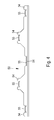
- all connecting pieces 21, 22, 23, 24 are in the receptacles 18 by means of a common, rail-shaped locking plate 50, as will be described later, locked.
- the locking plate 50 is here For example, by means of four mounting screws 51 in each case at the Mounting plate 10 formed mounting tabs 52 attached. It is also possible, only individual connecting pieces by means of a common locking plate 50 to lock.
- FIG. 3 shows a plan view of a single mounting plate 10.
- the Representation illustrates the formation of the images 18 for the individual Connecting piece 21, 22, 23, 24.
- Each receptacle 18 has an insertion portion 61, a guide portion 62 and a stopper portion 63.
- the stopper portion 63 is in depth with an angled sheet metal part, each with a stop 64th executed.
- 18 is the one for each receptacle Mounting plate 10 a securing portion 54 is formed, each one as a curved Sheet metal tab trained stop 55 is assigned.
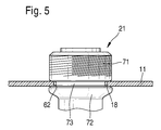
- the attachment of a connecting piece 21, 22, 23, 24 in the mounting plate 10 is on Example of the connecting piece 21 shown in Figure 5. It has the Connecting piece 21 a device-side connector body 71 and a line side Connection body 72 on.
- the line-side connector body 72 is shown in FIGS 2 equipped with the shut-off valve 26 and the 3-way valve 37.
- a Undercut 73 carried out, which is dimensioned in diameter so that these in the Holding portion 62 of the respective receptacle 18 of the mounting plate 10 engages and thereby the connection body in the receptacle 18 longitudinally displaceable until it stops 64 is inserted.
- the locking plate 50 is pushed on the front, wherein the Stops 55 of the securing portions 54 also at the respective stop neck attack and thus the connecting pieces 20, 21, 22, 23, 24 in the mounting plate 10th are fixed.
- the locking plate 50 is used only for Locking the connecting pieces 21, 22, 23, 24.
- the connecting piece 20 for the Gas fitting is then with a separate locking plate, a retaining ring or similar arrested.
Landscapes
- Engineering & Computer Science (AREA)
- Physics & Mathematics (AREA)
- Thermal Sciences (AREA)
- Chemical & Material Sciences (AREA)
- Combustion & Propulsion (AREA)
- Mechanical Engineering (AREA)
- General Engineering & Computer Science (AREA)
- Steam Or Hot-Water Central Heating Systems (AREA)
- Housings, Intake/Discharge, And Installation Of Fluid Heaters (AREA)
- Valve Housings (AREA)
Abstract
Description
- Figur 1
- eine Vorderansicht einer erfindungsgemäßen Anschlussvorrichtung mit hydraulischen Anschlüssen,
- Figur 2
- eine Draufsicht auf die Anschlussvorrichtung gemäß Figur 1,
- Figur 3
- eine Draufsicht auf eine unbestückte Montageplatte,
- Figur 4
- eine Draufsicht auf ein nicht montiertes Sicherungsblech und
- Figur 5
- eine Teilschnittdarstellung mit einem Anschlussstutzen.
- 10
- Montageplatte
- 11
- Stegteil
- 12
- Seitenteil
- 13
- Seitenteil
- 14
- Befestigungsteil
- 15
- Löcher
- 16
- Sicke
- 18
- Aufnahmen
- 19
- Gasanschluss
- 20
- Anschlussstutzen für Gasarmatur
- 21
- Anschlussstutzen
- 22
- Anschlussstutzen
- 23
- Anschlussstutzen
- 24
- Anschlussstutzen
- 25
- Absperrventil für Gasanschluss
- 26
- Absperrventil
- 27
- Absperrventil
- 28
- Absperrventil
- 31
- Heizungsvorlauf
- 32
- Heizungsrücklauf
- 33
- Einlassleitung
- 34
- Auslassleitung
- 36
- Absperrschieber
- 37
- 3-Wege-Ventil
- 39
- Bypassleitung
- 41
- Drossel
- 43
- 3-Wege-Ventil
- 50
- Sicherungsblech
- 51
- Befestigungsschrauben
- 52
- Befestigungslaschen
- 54
- Sicherungsabschnitt
- 55
- Anschlag
- 61
- Einführabschnitt
- 62
- Führungsabschnitt
- 63
- Anschlagabschnitt
- 64
- Anschlag
- 71
- geräteseitiger Anschlusskörper
- 72
- leitungsseitiger Anschlusskörper
- 73
- Hinterschneidung
Claims (3)
- Anschlussvorrichtung für ein Wandheizgerät mit einer an einer Wand befestigbaren Montageplatte (10), die mit bau- und geräteseitigen Anschlussstutzen (20, 21, 22, 23, 24), insbesondere für Wasser und Gas versehen ist, wobei die Anschlussstutzen in der Montageplatte (10) fixiert sind und gegebenenfalls Absperrventile enthalten oder mit diesen verbunden sind, dadurch gekennzeichnet, dass die Montageplatte (10) nach einer Seite hin offene Aufnahmen (18) für die Anschlussstutzen (20, 21, 22, 23, 24) aufweist und dass zumindest ein Teil der Anschlussstutzen (20, 21, 22, 23, 24) mittels eines gemeinsamen Sicherungsblechs (50), das an der Montageplatte (10) befestigbar ist, arretiert ist.
- Anschlussvorrichtung nach Anspruch 1, dadurch gekennzeichnet, dass die Aufnahme (18) einen Einführabschnitt (61), einen Halteabschnitt (62) und einen Anschlagabschnitt (63) aufweist, und dass der Anschlussstutzen (21, 22, 23, 24) mit einer Hinterschneidung (73) in den Halteabschnitt (62) einführbar ist.
- Anschlussvorrichtung nach Anspruch 2, dadurch gekennzeichnet, dass die Anschlussstutzen (20, 21, 22, 23, 24) an einem Anschlag (64) des Anschlagabschnitts (63) anliegen und dass frontal das Sicherungsblech (50) mit jeweils einem der jeweiligen Aufnahme (18) zugeordneten Sicherungsabschnitt (54) mittels eines Anschlags (55) ebenfalls am jeweiligen Anschlagstutzen (20, 21, 22, 23, 24) anliegt.
Applications Claiming Priority (2)
| Application Number | Priority Date | Filing Date | Title |
|---|---|---|---|
| DE102004011280 | 2004-03-09 | ||
| DE102004011280A DE102004011280A1 (de) | 2004-03-09 | 2004-03-09 | Anschlussvorrichtung für ein Wandheizgerät |
Publications (3)
| Publication Number | Publication Date |
|---|---|
| EP1574790A2 true EP1574790A2 (de) | 2005-09-14 |
| EP1574790A3 EP1574790A3 (de) | 2006-08-09 |
| EP1574790B1 EP1574790B1 (de) | 2009-06-17 |
Family
ID=34813616
Family Applications (1)
| Application Number | Title | Priority Date | Filing Date |
|---|---|---|---|
| EP05100193A Expired - Lifetime EP1574790B1 (de) | 2004-03-09 | 2005-01-14 | Anschlussvorrichtung für ein Wandheizgerät |
Country Status (3)
| Country | Link |
|---|---|
| EP (1) | EP1574790B1 (de) |
| DE (2) | DE102004011280A1 (de) |
| ES (1) | ES2327242T3 (de) |
Cited By (4)
| Publication number | Priority date | Publication date | Assignee | Title |
|---|---|---|---|---|
| WO2012088556A3 (de) * | 2010-12-30 | 2013-07-04 | Herz Armaturen Ges.M.B.H. | Montageplatte |
| EP3462104A1 (de) * | 2017-09-28 | 2019-04-03 | Daikin Industries, Ltd. | Heisswasserversorgungseinheit und verfahren zur herstellung dergleichen |
| EP4130601A4 (de) * | 2020-03-23 | 2023-12-06 | Toshiba Carrier Corporation | Heisswassererzeugungsvorrichtung |
| WO2024110645A1 (de) * | 2022-11-25 | 2024-05-30 | Envola GmbH | Verbindungssystem für bauteile zur temperaturkonditionierung eines gebäudes |
Families Citing this family (1)
| Publication number | Priority date | Publication date | Assignee | Title |
|---|---|---|---|---|
| DE102023210442A1 (de) * | 2023-10-23 | 2025-04-24 | Glen Dimplex Deutschland Gmbh | Rohrstück und Gerätemodul für eine Kraftwärmemaschine |
Family Cites Families (2)
| Publication number | Priority date | Publication date | Assignee | Title |
|---|---|---|---|---|
| DE29708221U1 (de) * | 1997-05-07 | 1998-09-03 | Robert Bosch Gmbh, 70469 Stuttgart | Anschlußvorrichtung für Wandheizgeräte |
| DE10109383C2 (de) * | 2001-02-27 | 2003-04-10 | Viessmann Gmbh & Co | Justierelementensatz für Gashähne |
-
2004
- 2004-03-09 DE DE102004011280A patent/DE102004011280A1/de not_active Ceased
-
2005
- 2005-01-14 EP EP05100193A patent/EP1574790B1/de not_active Expired - Lifetime
- 2005-01-14 ES ES05100193T patent/ES2327242T3/es not_active Expired - Lifetime
- 2005-01-14 DE DE502005007480T patent/DE502005007480D1/de not_active Expired - Lifetime
Cited By (4)
| Publication number | Priority date | Publication date | Assignee | Title |
|---|---|---|---|---|
| WO2012088556A3 (de) * | 2010-12-30 | 2013-07-04 | Herz Armaturen Ges.M.B.H. | Montageplatte |
| EP3462104A1 (de) * | 2017-09-28 | 2019-04-03 | Daikin Industries, Ltd. | Heisswasserversorgungseinheit und verfahren zur herstellung dergleichen |
| EP4130601A4 (de) * | 2020-03-23 | 2023-12-06 | Toshiba Carrier Corporation | Heisswassererzeugungsvorrichtung |
| WO2024110645A1 (de) * | 2022-11-25 | 2024-05-30 | Envola GmbH | Verbindungssystem für bauteile zur temperaturkonditionierung eines gebäudes |
Also Published As
| Publication number | Publication date |
|---|---|
| DE502005007480D1 (de) | 2009-07-30 |
| DE102004011280A1 (de) | 2005-09-29 |
| EP1574790B1 (de) | 2009-06-17 |
| EP1574790A3 (de) | 2006-08-09 |
| ES2327242T3 (es) | 2009-10-27 |
Similar Documents
| Publication | Publication Date | Title |
|---|---|---|
| EP2226432B1 (de) | Anschlussblock für Sanitärarmaturen | |
| EP0580551B1 (de) | Anschlussplatte zum Befestigen von beispielsweise sanitären Armaturen | |
| DE102013205250B4 (de) | Rohranschlussadapter und Sanitärarmatur | |
| EP2196584A1 (de) | Verteiler für eine Wasserleitungsanlage | |
| EP1574790A2 (de) | Anschlussvorrichtung für ein Wandheizgerät | |
| DE3826064A1 (de) | Anschlussanordnung fuer eine sanitaere mischarmatur | |
| EP0309397B2 (de) | Sanitäre Wasseranschlussanordnung | |
| EP2177690A1 (de) | Haltevorrichtung für eine Sicherungsbaugruppe, insbesondere für Fangwände oder -netze | |
| EP1760205A1 (de) | Anschlussblock für eine Sanitärarmatur und System von Sanitärarmaturen | |
| EP3055463B1 (de) | Vorrichtung zum anschluss von sanitärarmaturen | |
| EP1672286B1 (de) | Verteilervorrichtung für einen mit einem flüssigen Medium betriebenen Kreislauf einer Wärmeversorgungsanlage | |
| DE2930518C2 (de) | Einrichtung zum Anschluß einer Leitungsarmatur | |
| EP2479510A2 (de) | Ventilgarnitur sowie Heizkörper mit einer solchen | |
| EP1390586B1 (de) | Sanitärarmaturenblock | |
| DE4002798C2 (de) | Sanitärbatterie für Aufputzanbringung | |
| DE102009036071B3 (de) | Modulares Unterputz-System für die Herstellung von wandseitigen Anschlüssen für Sanitärarmaturen | |
| DE10057229B4 (de) | Wandanschlussfitting für Armaturen | |
| DE102020209623B4 (de) | Montageplatte zur Wandmontage zumindest zweier Installationsfittings, Montagesystem sowie Verfahren zur Montage | |
| EP4726279A1 (de) | Montageset für ein modul an einem heizungspufferspeicher | |
| DE202007017260U1 (de) | Armatur für fluide Medien und deren Anordnung | |
| DE3604932A1 (de) | Mehrfachanschluss-armatur fuer eine anschlussdose fuer brauchwasser-installationen | |
| DE20013996U1 (de) | Konvektionsbremse für Wärmequellen | |
| DE29818247U1 (de) | Heizkörper mit Anschlußschleife | |
| DE19542674C2 (de) | Integrierte Ventilgarnitur für Plattenheizkörper | |
| DE29702434U1 (de) | Verteilergruppe für Plattenheizkörper |
Legal Events
| Date | Code | Title | Description |
|---|---|---|---|
| PUAI | Public reference made under article 153(3) epc to a published international application that has entered the european phase |
Free format text: ORIGINAL CODE: 0009012 |
|
| AK | Designated contracting states |
Kind code of ref document: A2 Designated state(s): AT BE BG CH CY CZ DE DK EE ES FI FR GB GR HU IE IS IT LI LT LU MC NL PL PT RO SE SI SK TR |
|
| AX | Request for extension of the european patent |
Extension state: AL BA HR LV MK YU |
|
| PUAL | Search report despatched |
Free format text: ORIGINAL CODE: 0009013 |
|
| AK | Designated contracting states |
Kind code of ref document: A3 Designated state(s): AT BE BG CH CY CZ DE DK EE ES FI FR GB GR HU IE IS IT LI LT LU MC NL PL PT RO SE SI SK TR |
|
| AX | Request for extension of the european patent |
Extension state: AL BA HR LV MK YU |
|
| 17P | Request for examination filed |
Effective date: 20070209 |
|
| AKX | Designation fees paid |
Designated state(s): DE ES FR GB IT |
|
| 17Q | First examination report despatched |
Effective date: 20070913 |
|
| GRAP | Despatch of communication of intention to grant a patent |
Free format text: ORIGINAL CODE: EPIDOSNIGR1 |
|
| GRAS | Grant fee paid |
Free format text: ORIGINAL CODE: EPIDOSNIGR3 |
|
| GRAA | (expected) grant |
Free format text: ORIGINAL CODE: 0009210 |
|
| AK | Designated contracting states |
Kind code of ref document: B1 Designated state(s): DE ES FR GB IT |
|
| REG | Reference to a national code |
Ref country code: GB Ref legal event code: FG4D Free format text: NOT ENGLISH |
|
| REF | Corresponds to: |
Ref document number: 502005007480 Country of ref document: DE Date of ref document: 20090730 Kind code of ref document: P |
|
| REG | Reference to a national code |
Ref country code: ES Ref legal event code: FG2A Ref document number: 2327242 Country of ref document: ES Kind code of ref document: T3 |
|
| PLBE | No opposition filed within time limit |
Free format text: ORIGINAL CODE: 0009261 |
|
| STAA | Information on the status of an ep patent application or granted ep patent |
Free format text: STATUS: NO OPPOSITION FILED WITHIN TIME LIMIT |
|
| 26N | No opposition filed |
Effective date: 20100318 |
|
| REG | Reference to a national code |
Ref country code: FR Ref legal event code: PLFP Year of fee payment: 12 |
|
| REG | Reference to a national code |
Ref country code: FR Ref legal event code: PLFP Year of fee payment: 13 |
|
| REG | Reference to a national code |
Ref country code: FR Ref legal event code: PLFP Year of fee payment: 14 |
|
| PGFP | Annual fee paid to national office [announced via postgrant information from national office to epo] |
Ref country code: GB Payment date: 20180125 Year of fee payment: 14 Ref country code: ES Payment date: 20180201 Year of fee payment: 14 |
|
| PGFP | Annual fee paid to national office [announced via postgrant information from national office to epo] |
Ref country code: FR Payment date: 20180124 Year of fee payment: 14 Ref country code: IT Payment date: 20180126 Year of fee payment: 14 |
|
| REG | Reference to a national code |
Ref country code: DE Ref legal event code: R084 Ref document number: 502005007480 Country of ref document: DE |
|
| PGFP | Annual fee paid to national office [announced via postgrant information from national office to epo] |
Ref country code: DE Payment date: 20190326 Year of fee payment: 15 |
|
| GBPC | Gb: european patent ceased through non-payment of renewal fee |
Effective date: 20190114 |
|
| PG25 | Lapsed in a contracting state [announced via postgrant information from national office to epo] |
Ref country code: FR Free format text: LAPSE BECAUSE OF NON-PAYMENT OF DUE FEES Effective date: 20190131 |
|
| PG25 | Lapsed in a contracting state [announced via postgrant information from national office to epo] |
Ref country code: GB Free format text: LAPSE BECAUSE OF NON-PAYMENT OF DUE FEES Effective date: 20190114 |
|
| PG25 | Lapsed in a contracting state [announced via postgrant information from national office to epo] |
Ref country code: IT Free format text: LAPSE BECAUSE OF NON-PAYMENT OF DUE FEES Effective date: 20190114 |
|
| REG | Reference to a national code |
Ref country code: ES Ref legal event code: FD2A Effective date: 20200309 |
|
| PG25 | Lapsed in a contracting state [announced via postgrant information from national office to epo] |
Ref country code: ES Free format text: LAPSE BECAUSE OF NON-PAYMENT OF DUE FEES Effective date: 20190115 |
|
| REG | Reference to a national code |
Ref country code: DE Ref legal event code: R119 Ref document number: 502005007480 Country of ref document: DE |
|
| PG25 | Lapsed in a contracting state [announced via postgrant information from national office to epo] |
Ref country code: DE Free format text: LAPSE BECAUSE OF NON-PAYMENT OF DUE FEES Effective date: 20200801 |