EP1574841A1 - Détecteur de gaz photoacoustique - Google Patents
Détecteur de gaz photoacoustique Download PDFInfo
- Publication number
- EP1574841A1 EP1574841A1 EP04005482A EP04005482A EP1574841A1 EP 1574841 A1 EP1574841 A1 EP 1574841A1 EP 04005482 A EP04005482 A EP 04005482A EP 04005482 A EP04005482 A EP 04005482A EP 1574841 A1 EP1574841 A1 EP 1574841A1
- Authority
- EP
- European Patent Office
- Prior art keywords
- microphone
- gas sensor
- photoacoustic gas
- sensor according
- Prior art date
- Legal status (The legal status is an assumption and is not a legal conclusion. Google has not performed a legal analysis and makes no representation as to the accuracy of the status listed.)
- Withdrawn
Links
- 238000007789 sealing Methods 0.000 claims 1
- 239000011324 bead Substances 0.000 abstract 1
- 210000004027 cell Anatomy 0.000 description 32
- 238000004519 manufacturing process Methods 0.000 description 6
- 239000012528 membrane Substances 0.000 description 6
- 230000005855 radiation Effects 0.000 description 3
- 238000004026 adhesive bonding Methods 0.000 description 2
- 210000005056 cell body Anatomy 0.000 description 2
- 238000001514 detection method Methods 0.000 description 2
- 229910052751 metal Inorganic materials 0.000 description 2
- 239000002184 metal Substances 0.000 description 2
- 238000012545 processing Methods 0.000 description 2
- 230000003595 spectral effect Effects 0.000 description 2
- 229910001229 Pot metal Inorganic materials 0.000 description 1
- 239000000853 adhesive Substances 0.000 description 1
- 230000001070 adhesive effect Effects 0.000 description 1
- 229910052782 aluminium Inorganic materials 0.000 description 1
- XAGFODPZIPBFFR-UHFFFAOYSA-N aluminium Chemical compound [Al] XAGFODPZIPBFFR-UHFFFAOYSA-N 0.000 description 1
- 230000002238 attenuated effect Effects 0.000 description 1
- 230000002457 bidirectional effect Effects 0.000 description 1
- 238000010276 construction Methods 0.000 description 1
- 238000002788 crimping Methods 0.000 description 1
- 230000001419 dependent effect Effects 0.000 description 1
- 238000011161 development Methods 0.000 description 1
- 230000018109 developmental process Effects 0.000 description 1
- 230000007613 environmental effect Effects 0.000 description 1
- 238000002474 experimental method Methods 0.000 description 1
- 230000000737 periodic effect Effects 0.000 description 1
- 238000005476 soldering Methods 0.000 description 1
- 238000001228 spectrum Methods 0.000 description 1
- 230000001629 suppression Effects 0.000 description 1
Images
Classifications
-
- G—PHYSICS
- G01—MEASURING; TESTING
- G01N—INVESTIGATING OR ANALYSING MATERIALS BY DETERMINING THEIR CHEMICAL OR PHYSICAL PROPERTIES
- G01N21/00—Investigating or analysing materials by the use of optical means, i.e. using sub-millimetre waves, infrared, visible or ultraviolet light
- G01N21/17—Systems in which incident light is modified in accordance with the properties of the material investigated
- G01N21/1702—Systems in which incident light is modified in accordance with the properties of the material investigated with opto-acoustic detection, e.g. for gases or analysing solids
- G01N2021/1704—Systems in which incident light is modified in accordance with the properties of the material investigated with opto-acoustic detection, e.g. for gases or analysing solids in gases
Definitions
- the present invention relates to a photoacoustic gas sensor with a measuring and a Reference cell, a spotlight and a differential microphone for measuring the pressure difference between measuring and reference cell.
- the difference microphone by a called Noise Canceling microphone is formed of the type used in mobile phones.
- a first preferred embodiment of the gas sensor according to the invention is characterized characterized in that the differential microphone electrodes in the form of concentric Has circular rings.
- the lower corner frequency of the difference microphone is less than 10Hz and is preferably between 1 and 4Hz.
- a second preferred embodiment is characterized in that the differential microphone a can-shaped housing whose bottom the front of the microphone forms and whose back has a flange for fixing a back plate.
- a third preferred embodiment is characterized in that the differential microphone is mounted on a print, which has a first annular groove for the positioning of having called curl.
- the microphone electrodes in the form of concentric circular rings have the advantage that the Parts do not need to be aligned when populating the print, which is a simple Mounting with a robot allows.
- the simple assembly is made by the first ring groove additionally relieved, because thereby the microphone with its case flange automatically is guided in the right position.
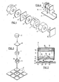
- the photoacoustic gas sensor shown in Figure 1 consists of a measuring cell 1, a Reference cell 2, a arranged between the two cells 1 and 2 bidirectional Differential microphone 3, one of the measuring cell 1 associated micro light bulb 4 and a Reflector housing 5 with a reflector for focusing the emitted from the micro-lamp 4 Radiation on a in the micro light bulb 4 facing side wall of Measuring cell 1 arranged window into which an infrared bandpass filter 6 is inserted.
- Measuring cell 1 and reference cell 2 are absolutely identical in terms of construction and dimensions. Both the measuring cell 1 and the reference cell 2 are on an outer side wall with a bore provided, in which a gas-permeable membrane 7 or 7 'used is.
- the differential microphone 3 is mounted on a print 8 and on both sides of the Difference microphones 3 each have a seal 9 (optional) is provided.
- the micro-bulb 4 is also mounted on a print, which is designated by the reference numeral 10.
- the micro-bulb 4 emits light over a wide spectrum down to the infrared range; In most cases, a spectral line in the infrared range is used for gas detection.
- the infrared bandpass filter 6 has a characteristic of the gas to be detected passband in the form of a narrow spectral band, which is for the detection of CO 2 at 4.25 microns, NH 3 at 10 microns and CH 4 at 3.4 microns.
- the gas to be detected passes through the two gas-permeable membranes 7 and 7 'in the measuring cell 1 and in the reference cell 2.
- the present in the measuring cell 1 gas is irradiated by modulated light of the micro-lamp 4.
- the gas absorbs the light radiation and heats up. This results in a thermal expansion and, according to the modulation of the light radiation, a periodic pressure fluctuation, so that an acoustic pressure wave is caused whose strength is in direct proportion to the concentration of the gas.
- the noise which strikes the membranes 7, 7 'from the outside, is attenuated by them the measuring cell 1 and the reference cell 2 each occur with identical strength.
- This background noise thus compensates directly on the membrane of the microphone 3, without large signals arise, which would have to be subtracted electronically. Because on both sides of the microphone diaphragm the same pressure fluctuations prevail, finds a direct physical Subtraction of the signals caused by background noise, so that the microphone diaphragm not even distracted.
- the microphone diaphragm thus provides directly by the Gas in the measuring cell 1 caused acoustic pressure and thus the concentration sought.
- the microphone 3 is a so-called “noise canceling" microphone, as in mobile phones Application finds. If this microphone is used as a differential microphone and between two acoustically practically closed cells, namely between measuring cell 1 and reference cell 2, is installed, it shows very good, tailored to the task properties.
- the microphone 3 is shown in section.
- This consists of the representation a unilaterally open housing G of the shape of a box, the bottom of the front of the Microphones forms.
- holes 11 for the sound passage to the between the bottom of the housing 10 and a metal baking electrode 12 clamped microphone membrane 13 provided of metallized plastic.
- the side wall of the housing 18 is flanged at the back of the microphone and fixes a rear wall 14, with small Equalizing holes, so-called back ports 15 are provided and at their the metal baking electrode 12 facing inside a FET 16 and on its outside two circular electrodes 17 and 19 carries.
- the back ports 15 are sufficiently large for low frequencies and make the frequency response of the microphone 3 to the lower corner frequency flat.
- This lower corner frequency is due to the Capacity of the diaphragm 13 and the input resistance of the impedance converter used determined and is well below 10Hz, preferably between 1 and 4Hz, so that the Signal at the useful frequency of about 20 to 30Hz from the lower corner frequency only is negligibly affected.
- the microphone 3 is mounted on the print 8, which has an annular groove 19 for the positioning of Crimping of the microphone 3, annular contact webs 20 and 21 for the two circular electrodes 17 and 18, and an annular groove 22 with some of the bottom of the annular groove through the Print 8 guided holes 23 has.
- the holes 23 and the annular groove 22 allow the supply of air and sound from the outside to the back ports 15 without them on any holes must be aligned in the print 8.
- the microphone 3 and the print 8 need not be aligned when loading, which allows easy assembly with a robot.
- the assembly is still through the annular groove 19 facilitates the microphone 3 with its housing flange when placing automatically in the right position leads.
- the circular electrodes 17 and 18 are connected to the circuit board 17 with Leitepoxy glued and electrically connected.
- the outer contour of measuring cell 1, reference cell 2 and the reflector housing 5 is consistent throughout, so that the parts as Pull extruded profiles cost-effectively and keep the necessary processing to a minimum is reduced.
- the production / provision of the individual components of the sensor i. of the reflector 5 with its housing, the two Cell body for measuring cell 1 and reference cell 2, the bandpass filter 6, the microphone 3 and the Mikroglühlampe 4.
- the bandpass filter 6 is glued into the measuring cell 1 and then the Microphone 3 mounted on the print 8.
- Measuring cell 1 and reference cell 2 are preferably made made of aluminum or die-cast zinc.
- FIG. 4 which is done by the batch batch processing shown in FIG. It is in each case a reference cell 2 with the populated microphone print 8, the measuring cell 1, the the reflector 24 containing reflector housing 5, in which the micro-lamp 4 is inserted is connected to the populated microglamp print 10 in a stack, either by gluing or by clamping together.
- the seals 9 (Fig. 1) is not required, because by the adhesive bond, the interior of the cell body 1 and 2 is sealed.
- the clamping takes place by means of a longitudinal direction of the sensor (Direction of the arrows in Fig. 3) acting resilient member, such as a clip.
- the membranes 7, 7 'used In the measuring cell 1 and the reference cell 2 of the finished measuring module M are subsequently the membranes 7, 7 'used and finally the measuring module M on a Modulprint P equipped, which can be done by gluing or soldering.
- the pre-assembled measuring module M is complete and functional and can be tested in advance as a unit before it on the Modulprint P is populated.
- the measuring module M can be used on any other circuit boards such as a component are inserted as a sub-module, wherein for the microphone 3, the reflector 24 and the Micro light bulb 4 no tolerance or alignment problems arise.
Landscapes
- Physics & Mathematics (AREA)
- Health & Medical Sciences (AREA)
- Life Sciences & Earth Sciences (AREA)
- Chemical & Material Sciences (AREA)
- Analytical Chemistry (AREA)
- Biochemistry (AREA)
- General Health & Medical Sciences (AREA)
- General Physics & Mathematics (AREA)
- Immunology (AREA)
- Pathology (AREA)
- Investigating Or Analysing Materials By Optical Means (AREA)
- Investigating Or Analyzing Materials By The Use Of Ultrasonic Waves (AREA)
Priority Applications (5)
| Application Number | Priority Date | Filing Date | Title |
|---|---|---|---|
| EP04005482A EP1574841A1 (fr) | 2004-03-08 | 2004-03-08 | Détecteur de gaz photoacoustique |
| PL05373064A PL373064A1 (en) | 2004-03-08 | 2005-02-22 | Photoacoustic gas sensor |
| AU2005200839A AU2005200839A1 (en) | 2004-03-08 | 2005-02-24 | Photoacoustic gas sensor |
| KR1020050019244A KR20060043530A (ko) | 2004-03-08 | 2005-03-08 | 광음향 가스 센서 |
| CNB2005100545004A CN100514031C (zh) | 2004-03-08 | 2005-03-08 | 光声气敏元件 |
Applications Claiming Priority (1)
| Application Number | Priority Date | Filing Date | Title |
|---|---|---|---|
| EP04005482A EP1574841A1 (fr) | 2004-03-08 | 2004-03-08 | Détecteur de gaz photoacoustique |
Publications (1)
| Publication Number | Publication Date |
|---|---|
| EP1574841A1 true EP1574841A1 (fr) | 2005-09-14 |
Family
ID=34814267
Family Applications (1)
| Application Number | Title | Priority Date | Filing Date |
|---|---|---|---|
| EP04005482A Withdrawn EP1574841A1 (fr) | 2004-03-08 | 2004-03-08 | Détecteur de gaz photoacoustique |
Country Status (5)
| Country | Link |
|---|---|
| EP (1) | EP1574841A1 (fr) |
| KR (1) | KR20060043530A (fr) |
| CN (1) | CN100514031C (fr) |
| AU (1) | AU2005200839A1 (fr) |
| PL (1) | PL373064A1 (fr) |
Cited By (3)
| Publication number | Priority date | Publication date | Assignee | Title |
|---|---|---|---|---|
| EP2604998A1 (fr) * | 2011-12-12 | 2013-06-19 | ABB Research Ltd. | Dispositif d'analyse de gaz |
| US8848191B2 (en) | 2012-03-14 | 2014-09-30 | Honeywell International Inc. | Photoacoustic sensor with mirror |
| EP3550286A1 (fr) * | 2019-04-17 | 2019-10-09 | Sensirion AG | Dispositif de capteur de gaz photoacoustique |
Families Citing this family (2)
| Publication number | Priority date | Publication date | Assignee | Title |
|---|---|---|---|---|
| KR20160061492A (ko) | 2014-11-21 | 2016-06-01 | 삼성디스플레이 주식회사 | 휴대용 먼지 센서 및 이를 이용한 휴대전화 |
| CN110596236A (zh) * | 2019-09-27 | 2019-12-20 | 湖北晟正汽车零部件有限公司 | 一种优化的尿素溶液浓度检测装置 |
Citations (8)
| Publication number | Priority date | Publication date | Assignee | Title |
|---|---|---|---|---|
| US4019056A (en) * | 1975-04-28 | 1977-04-19 | Diax Corporation | Infrared laser detector employing a pressure controlled differential optoacoustic detector |
| US4067653A (en) * | 1976-08-27 | 1978-01-10 | Nasa | Differential optoacoustic absorption detector |
| US4456796A (en) * | 1981-03-25 | 1984-06-26 | Hosiden Electronics Co., Ltd. | Unidirectional electret microphone |
| US4887300A (en) * | 1986-07-17 | 1989-12-12 | Aktieselskabet Bruel & Kjaer | Pressure gradient microphone |
| DE4018393A1 (de) * | 1989-06-13 | 1990-12-20 | Oehler Oscar | Verfahren und vorrichtung zum messen von photosynthese-austauschgasen |
| EP0742678A2 (fr) * | 1995-05-11 | 1996-11-13 | AT&T Corp. | Microphone à gradient avec suppression de bruit |
| WO1999030122A1 (fr) * | 1997-11-26 | 1999-06-17 | Presens As | Capteur de pression dynamique, detecteur de gaz photo-acoustique, microphone, hydrophone et leur fabrication |
| US6647118B1 (en) * | 1999-07-27 | 2003-11-11 | Nec Infrontia Corporation | Noise canceling microphone unit for composing noise canceling handset by using normal housing |
-
2004
- 2004-03-08 EP EP04005482A patent/EP1574841A1/fr not_active Withdrawn
-
2005
- 2005-02-22 PL PL05373064A patent/PL373064A1/xx not_active Application Discontinuation
- 2005-02-24 AU AU2005200839A patent/AU2005200839A1/en not_active Abandoned
- 2005-03-08 KR KR1020050019244A patent/KR20060043530A/ko not_active Withdrawn
- 2005-03-08 CN CNB2005100545004A patent/CN100514031C/zh not_active Expired - Fee Related
Patent Citations (8)
| Publication number | Priority date | Publication date | Assignee | Title |
|---|---|---|---|---|
| US4019056A (en) * | 1975-04-28 | 1977-04-19 | Diax Corporation | Infrared laser detector employing a pressure controlled differential optoacoustic detector |
| US4067653A (en) * | 1976-08-27 | 1978-01-10 | Nasa | Differential optoacoustic absorption detector |
| US4456796A (en) * | 1981-03-25 | 1984-06-26 | Hosiden Electronics Co., Ltd. | Unidirectional electret microphone |
| US4887300A (en) * | 1986-07-17 | 1989-12-12 | Aktieselskabet Bruel & Kjaer | Pressure gradient microphone |
| DE4018393A1 (de) * | 1989-06-13 | 1990-12-20 | Oehler Oscar | Verfahren und vorrichtung zum messen von photosynthese-austauschgasen |
| EP0742678A2 (fr) * | 1995-05-11 | 1996-11-13 | AT&T Corp. | Microphone à gradient avec suppression de bruit |
| WO1999030122A1 (fr) * | 1997-11-26 | 1999-06-17 | Presens As | Capteur de pression dynamique, detecteur de gaz photo-acoustique, microphone, hydrophone et leur fabrication |
| US6647118B1 (en) * | 1999-07-27 | 2003-11-11 | Nec Infrontia Corporation | Noise canceling microphone unit for composing noise canceling handset by using normal housing |
Cited By (5)
| Publication number | Priority date | Publication date | Assignee | Title |
|---|---|---|---|---|
| EP2604998A1 (fr) * | 2011-12-12 | 2013-06-19 | ABB Research Ltd. | Dispositif d'analyse de gaz |
| US8848191B2 (en) | 2012-03-14 | 2014-09-30 | Honeywell International Inc. | Photoacoustic sensor with mirror |
| EP3550286A1 (fr) * | 2019-04-17 | 2019-10-09 | Sensirion AG | Dispositif de capteur de gaz photoacoustique |
| WO2020212481A1 (fr) * | 2019-04-17 | 2020-10-22 | Sensirion Ag | Dispositif de capteur photoacoustique de gaz |
| US11754492B2 (en) | 2019-04-17 | 2023-09-12 | Sensirion Ag | Photoacoustic gas sensor device |
Also Published As
| Publication number | Publication date |
|---|---|
| AU2005200839A1 (en) | 2005-09-22 |
| CN100514031C (zh) | 2009-07-15 |
| CN1667396A (zh) | 2005-09-14 |
| PL373064A1 (en) | 2005-09-19 |
| KR20060043530A (ko) | 2006-05-15 |
Similar Documents
| Publication | Publication Date | Title |
|---|---|---|
| DE69333058T2 (de) | Piezoelektrischer Wandler | |
| DE19923985A1 (de) | Sensorbaugruppe mit einem an einer Wand montierbaren Gehäuse | |
| DE69523811T2 (de) | Differentialer Zweiteordnungsmikrofonaufbau, mit einer einzigen Membran | |
| EP1897365B1 (fr) | Systeme de camera comprenant un element d'etancheite de capteur d'image qui sert de protection contre les effets de l'environnement exterieur | |
| EP0129714A2 (fr) | Condensateur électrique | |
| DE69811936T2 (de) | Linearer lautsprecher | |
| EP0779170B1 (fr) | Détecteur d'agents polluants | |
| DE2906497C2 (fr) | ||
| EP2281183B1 (fr) | Capteur de pression d'air pour détecter une collision | |
| DE102020135152A1 (de) | Unsichtbare mikrofonbaugruppe für ein fahrzeug | |
| DE102014113355A1 (de) | Lautsprecherabdeckung | |
| EP1574841A1 (fr) | Détecteur de gaz photoacoustique | |
| EP1574840A1 (fr) | Détecteur de gaz photoacoustique et son procédé de fabrication | |
| WO2021110429A1 (fr) | Capteur de pression relative comprenant une chambre de séchage | |
| DE102005053014B4 (de) | Drucksensorgehäuse und Verfahren zu seiner Herstellung | |
| DE102021210581A1 (de) | Zugangselement für Medien an einem Sensor sowie Sensor mit einem derartigen Zugangselement | |
| EP1582857A1 (fr) | Détecteur de gaz photoacoustique comprenant une source de lumière avec réflecteur, et méthode pour optimiser le contour du réflecteur | |
| DE60006909T2 (de) | Gerät mit elektroakustischem wandler in einer pc-platine montiert mit hilfe von halteeinrichtungen | |
| WO2003087752A1 (fr) | Capteur de pression | |
| DE20119461U1 (de) | Elektromotorischer Antrieb mit Druckausgleichsvorrichtung | |
| DE3013684C2 (de) | Klopfsensor | |
| DE10057912A1 (de) | Druckausgleichselement für Steckverbindungen | |
| DE4411853C2 (de) | Optoakustischer Gassensor zur gleichzeitigen Detektion von mehreren Komponenten eines Gasgemisches | |
| DE102018202098B3 (de) | Fahrzeugdachantenne | |
| DE112020002144T5 (de) | Umwandlungselement-bauteil und umwandlungselement-modul sowie elektronische vorrichtung, die das umwandlungselement-bauteil umfasst |
Legal Events
| Date | Code | Title | Description |
|---|---|---|---|
| PUAI | Public reference made under article 153(3) epc to a published international application that has entered the european phase |
Free format text: ORIGINAL CODE: 0009012 |
|
| AK | Designated contracting states |
Kind code of ref document: A1 Designated state(s): AT BE BG CH CY CZ DE DK EE ES FI FR GB GR HU IE IT LI LU MC NL PL PT RO SE SI SK TR |
|
| AX | Request for extension of the european patent |
Extension state: AL LT LV MK |
|
| RAP1 | Party data changed (applicant data changed or rights of an application transferred) |
Owner name: SIEMENS SCHWEIZ AG |
|
| 17P | Request for examination filed |
Effective date: 20051010 |
|
| AKX | Designation fees paid |
Designated state(s): AT BE BG CH CY CZ DE DK EE ES FI FR GB GR HU IE IT LI LU MC NL PL PT RO SE SI SK TR |
|
| RAP1 | Party data changed (applicant data changed or rights of an application transferred) |
Owner name: SIEMENS AKTIENGESELLSCHAFT |
|
| STAA | Information on the status of an ep patent application or granted ep patent |
Free format text: STATUS: THE APPLICATION IS DEEMED TO BE WITHDRAWN |
|
| 18D | Application deemed to be withdrawn |
Effective date: 20100112 |