EP1574869B1 - Schaltungsanordnung zur Detektion eines Kriech- oder Defektstroms - Google Patents
Schaltungsanordnung zur Detektion eines Kriech- oder Defektstroms Download PDFInfo
- Publication number
- EP1574869B1 EP1574869B1 EP05005098A EP05005098A EP1574869B1 EP 1574869 B1 EP1574869 B1 EP 1574869B1 EP 05005098 A EP05005098 A EP 05005098A EP 05005098 A EP05005098 A EP 05005098A EP 1574869 B1 EP1574869 B1 EP 1574869B1
- Authority
- EP
- European Patent Office
- Prior art keywords
- line
- signal line
- circuit
- free
- conductor
- Prior art date
- Legal status (The legal status is an assumption and is not a legal conclusion. Google has not performed a legal analysis and makes no representation as to the accuracy of the status listed.)
- Expired - Lifetime
Links
- 239000004020 conductor Substances 0.000 claims abstract description 21
- 238000009413 insulation Methods 0.000 claims abstract description 4
- 238000000034 method Methods 0.000 claims description 4
- 238000004891 communication Methods 0.000 claims description 3
- 238000005476 soldering Methods 0.000 claims description 2
- 230000007547 defect Effects 0.000 abstract description 6
- 238000001514 detection method Methods 0.000 abstract 1
- 238000005868 electrolysis reaction Methods 0.000 description 6
- 238000011156 evaluation Methods 0.000 description 5
- FAPWRFPIFSIZLT-UHFFFAOYSA-M Sodium chloride Chemical compound [Na+].[Cl-] FAPWRFPIFSIZLT-UHFFFAOYSA-M 0.000 description 4
- 230000006378 damage Effects 0.000 description 3
- 230000007613 environmental effect Effects 0.000 description 3
- 239000007789 gas Substances 0.000 description 3
- XLYOFNOQVPJJNP-UHFFFAOYSA-N water Substances O XLYOFNOQVPJJNP-UHFFFAOYSA-N 0.000 description 3
- 239000010416 ion conductor Substances 0.000 description 2
- 238000004519 manufacturing process Methods 0.000 description 2
- 238000012544 monitoring process Methods 0.000 description 2
- 150000003839 salts Chemical class 0.000 description 2
- 238000011144 upstream manufacturing Methods 0.000 description 2
- 238000009736 wetting Methods 0.000 description 2
- KZBUYRJDOAKODT-UHFFFAOYSA-N Chlorine Chemical compound ClCl KZBUYRJDOAKODT-UHFFFAOYSA-N 0.000 description 1
- UFHFLCQGNIYNRP-UHFFFAOYSA-N Hydrogen Chemical compound [H][H] UFHFLCQGNIYNRP-UHFFFAOYSA-N 0.000 description 1
- 208000027418 Wounds and injury Diseases 0.000 description 1
- 230000001419 dependent effect Effects 0.000 description 1
- 239000003792 electrolyte Substances 0.000 description 1
- 239000001257 hydrogen Substances 0.000 description 1
- 229910052739 hydrogen Inorganic materials 0.000 description 1
- 208000014674 injury Diseases 0.000 description 1
- 230000007257 malfunction Effects 0.000 description 1
- 239000000463 material Substances 0.000 description 1
- 230000001681 protective effect Effects 0.000 description 1
- 239000012266 salt solution Substances 0.000 description 1
- 239000007921 spray Substances 0.000 description 1
- 239000000126 substance Substances 0.000 description 1
- 230000007704 transition Effects 0.000 description 1
- 230000001960 triggered effect Effects 0.000 description 1
Images
Classifications
-
- G—PHYSICS
- G01—MEASURING; TESTING
- G01R—MEASURING ELECTRIC VARIABLES; MEASURING MAGNETIC VARIABLES
- G01R31/00—Arrangements for testing electric properties; Arrangements for locating electric faults; Arrangements for electrical testing characterised by what is being tested not provided for elsewhere
- G01R31/28—Testing of electronic circuits, e.g. by signal tracer
- G01R31/30—Marginal testing, e.g. by varying supply voltage
- G01R31/3004—Current or voltage test
-
- G—PHYSICS
- G01—MEASURING; TESTING
- G01R—MEASURING ELECTRIC VARIABLES; MEASURING MAGNETIC VARIABLES
- G01R31/00—Arrangements for testing electric properties; Arrangements for locating electric faults; Arrangements for electrical testing characterised by what is being tested not provided for elsewhere
- G01R31/005—Testing of electric installations on transport means
- G01R31/006—Testing of electric installations on transport means on road vehicles, e.g. automobiles or trucks
-
- G—PHYSICS
- G01—MEASURING; TESTING
- G01R—MEASURING ELECTRIC VARIABLES; MEASURING MAGNETIC VARIABLES
- G01R31/00—Arrangements for testing electric properties; Arrangements for locating electric faults; Arrangements for electrical testing characterised by what is being tested not provided for elsewhere
- G01R31/50—Testing of electric apparatus, lines, cables or components for short-circuits, continuity, leakage current or incorrect line connections
- G01R31/52—Testing for short-circuits, leakage current or ground faults
Definitions
- the invention relates to a circuit arrangement for detecting a creepage or defect current, by means of which the voltage supply of an electronic circuit can be switched off and a method for operating such a circuit arrangement.
- Electronic or mechatronic components such as those installed in the vehicle industry such environmental influences on the vehicle frame, are usually powered by a switched on-board voltage.
- monitoring circuits can turn off many circuit parts.
- the voltage applied directly to the plug of the power supply lines can only be switched off by a monitoring circuit of an upstream component.
- the shutdown can be done, for example, after measuring an excessive power consumption or in the simplest case by a responsive in excessive current fuse.
- the change in power consumption is very small and indistinguishable from the large fluctuations subject to regular power consumption.
- the electrolysis leads to a fire although a significant increase in power can be measured, to prevent a fire the power supply would have had to be switched off beforehand.
- the invention has for its object to provide a circuit arrangement for detecting a creepage or defect current, by means of which the power supply of an electronic circuit can be switched off with onset of fault current before the fault current reaches a fire-endangering extent.
- the circuit arrangement according to the invention for detecting a creeping or defect current by means of which the voltage supply of an electronic circuit can be switched off, has a conductor path connected to a signal line or an insulator-free conductor or an insulating layer-free part of the signal line itself, arranged in such a way in that it crosses a potential leakage path of a short circuit between the power supply lines.
- the trace or the insulation-layer free conductor crosses a potential leakage path of a short circuit between the power supply lines
- the trace or the insulation-layer-free conductor exactly crosses the connection line between the leakage current entry and exit points on the power supply lines He / it in relation to the current distribution of the leakage current, this proportionately traverses such that a consequent electrical signal on the signal line with standard electronic means is receivable.
- the basic idea of the invention here is that the signal line or a stub thereof is structurally designed so that it is influenced by a fault current, for example due to wetting with an ion conductor such as a saline solution. An upstream electronic component with an evaluation circuit can detect this influence and switch off the supply voltage early and thus prevent a fire.
- the conductor path connected to a signal line or the insulation layer-free conductor or the insulating layer-free part of the signal line are arranged between two insulation-free connection surfaces, in particular soldering surfaces or bonding surfaces of the voltage supply lines.
- a leakage current between these two contact surfaces, as caused by wetting with an ionic conductor such as a saline solution, is traversed by the signal line or a stub thereof and sets this to an intermediate potential.
- the signal line or a stub thereof acts like a pickup of a voltage divider.
- the signal line is a sensor line or a communication line, in particular a CAN bus line. This can be done by an evaluation of the sensor signal or by an evaluation of a corruption of the communication signal a fault current can be detected.
- the conductor path connected to a signal line or the insulating layer-free conductor is a stub line of a CAN line.
- An evaluation logic preferably detects a creepage or defect current on the basis of the potential level, a signal corruption or a disturbance in the data flow of the signal line.
- circuit arrangement according to the invention come especially to bear when the circuit arrangement is part of an electronic electronic brake system EBS.
- Electronic circuits in electropneumatic modulators are particularly vulnerable due to the attachment of the electro-pneumatic modulators to the frame of commercial vehicles in case of housing leaks and entry of salt water from the road.
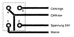
- the single FIGURE shows a circuit board of a circuit arrangement according to the invention in a highly simplified, schematic representation.
- a contact point 1 is a ground line of a power supply
- a contact point 2 is a 24 V voltage leading line of the power supply
- at a contact point 3 is a "CAN-high” line of a signal conductor pair and at a contact point 4 a "CAN-low” cable of a signal conductor pair attached.
- circuit board If the circuit board is wetted with a saline solution layer which extends continuously from the contact point 1 to the contact point 2 and thus establishes a conductive connection between the two voltage supply contact points, this results in a fault current between the voltage supply contact points.
- This fault current path crosses the stub line and sets it and thus the "CAN-low" line to a potential between 0 and 24 V.
- This potential change can be used to detect a fault current from an evaluation logic connected to the "CAN-low” line.
- the power supply is then turned off and the electrolysis process at the voltage supply contact points in the transition from electronic to ionic conduction suppressed. The risk of fire due to the released electrolysis gases is thus banned.
Landscapes
- Physics & Mathematics (AREA)
- General Physics & Mathematics (AREA)
- Engineering & Computer Science (AREA)
- General Engineering & Computer Science (AREA)
- Chemical & Material Sciences (AREA)
- Combustion & Propulsion (AREA)
- Testing Of Short-Circuits, Discontinuities, Leakage, Or Incorrect Line Connections (AREA)
- Electric Propulsion And Braking For Vehicles (AREA)
- Emergency Protection Circuit Devices (AREA)
Description
- Die Erfindung betrifft eine Schaltungsanordnung zur Detektion eines Kriech- oder Defektstroms, mittels derer die Spannungsversorgung einer elektronischen Schaltung abschaltbar ist sowie ein Verfahren zum Betreiben einer derartigen Schaltungsanordnung.
- Bei aufgrund ihres Einsatzortes Umwelteinflüssen ausgesetzten elektronischen Steuergeräten können bei Beschädigung des Schutzgehäuses Undichtigkeiten entstehen, durch die Fremdstoffe in den Elektronikraum eindringen können, welche die Funktion stören und sogar einen Brand auslösen können. Elektrolythaltige Spritzwassereinträge, insbesondere Salzlösungen stellen eine solche Gefahr dar. Gelangt Salzlösung zwischen spannungsführende Kontaktstellen, fließt ein ionischer Fehlstrom. Durch die damit verbundene Elektrolyse kann dies in bestimmten Situationen zum Brand führen. Solange die elektronische Funktionalität des Steuergeräts nicht in der Weise beeinflusst wird, dass das Steuergerät wegen Fehlfunktion abgeschaltet wird, wird die brandfördemde elektrolytische Produktion von beispielsweise Wasserstoff und Chlorgas fortgesetzt. Diese Problematik von Umwelteinflüssen ausgesetzten elektronischen Steuergeräten wiegt insbesondere in der Fahrzeugindustrie schwer, bei der gerade im Nutzfahrzeugsektor elektronische Steuergeräte direkt am Lkw-Rahmen angebracht und dem aufspritzenden Salzwasser der winterlichen Straße voll ausgesetzt sind. Eine in einem beschädigten Steuergerät nicht erkannte Produktion von Elektrolysegasen und ein dadurch ausgelöster Brand können insbesondere in einem Tunnel zu verheerenden Personen- und Sachschäden führen.
- Elektronische oder mechatronische Komponenten nach dem Stand der Technik, wie sie beispielsweise in der Fahrzeugindustrie solchen Umwelteinflüssen ausgesetzt am Fahrzeugrahmen eingebaut werden, werden in der Regel über eine geschaltete Bordspannung versorgt. Innerhalb solcher Komponenten können Überwachungsschaltungen viele Schaltungsteile abschalten. Die direkt am Stecker der Stromzuführungsleitungen anliegende Spannung kann aber nur von einer Überwachungsschaltung einer vorgeschalteten Komponente abgeschaltet werden. Die Abschaltung kann beispielsweise nach Messung einer überhöhten Stromaufnahme oder im einfachsten Fall durch eine bei überhöhtem Strom ansprechenden Sicherung erfolgen. Mit beginnendem Aufkommen des Elektrolysegase freisetzenden Fehlstroms ist die Änderung der Stromaufnahme aber sehr gering und von der großen Schwankungen unterworfenen regulären Stromaufnahme nicht zu unterscheiden. Zu dem Zeitpunkt, an dem die Elektrolyse zu einem Brand führt, ist zwar eine signifikante Stromerhöhung messbar, zur Verhinderung eines Brandes hätte die Stromzufuhr aber bereits vorher abgeschaltet werden müssen.
- Aus der
US 962 934 A1 und derDE 3900040A1 sind Vorrichtungen zur Detektierung von Detektströmen bekannt. - Der Erfindung liegt die Aufgabe zugrunde, eine Schaltungsanordnung zur Detektion eines Kriech- oder Defektstroms zu schaffen, mittels derer die Spannungsversorgung einer elektronischen Schaltung mit einsetzendem Fehlstrom abgeschaltet werden kann, bevor der Fehlstrom ein brandgefährdendes Ausmaß erreicht.
- Diese Aufgabe wird gelöst durch eine Vorrichtung mit den Merkmalen des Anspruchs 1 und ein Verfahren mit den Merkmalen des Anspruchs 7. Vorteilhafte Ausgestaltungen ergeben sich aus den Unteransprüchen.
- Die erfindungsgemäße Schaltungsanordnung zur Detektion eines Kriech- oder Defektstroms, mittels derer die Spannungsversorgung einer elektronischen Schaltung abschaltbar ist, weist eine mit einer Signalleitung verbundene Leiterbahn oder einen isolationsschichtfreien Leiter oder einen isolationsschichtfreien Teil der Signalleitung selbst auf, die / der derart angeordnet ist, dass sie / er eine potentielle Kriechstromverbindungsstrecke eines Kurzschlusses zwischen den Spannungsversorgungsleitungen kreuzt. Darunter, dass die Leiterbahn oder der isolationsschichtfreie Leiter eine potentielle Kriechstromverbindungsstrecke eines Kurzschlusses zwischen den Spannungsversorgungsleitungen kreuzt, ist nicht nur zu verstehen, dass die Leiterbahn oder der isolationsschichtfreie Leiter genau die Verbindungslinie zwischen den Kriechstromeintritts- und -austrittsstellen an den Stromversorgungsleitungen kreuzt, sondern dass sie/er in Bezug auf die Stromverteilung des Kriechstroms diesen anteilig derart durchquert, dass ein dadurch bedingtes elektrisches Signal auf der Signalleitung mit elektronischen Standardmitteln aufnehmbar ist. Der grundsätzliche Erfindungsgedanke hierbei ist, dass die Signalleitung oder eine Stichleitung davon konstruktiv so ausgeführt ist, dass sie von einem Fehlstrom beispielsweise bedingt durch eine Benetzung mit einem lonenleiter wie beispielsweise einer Salzlösung beeinflusst wird. Eine vorgeschaltete elektronische Komponente mit einer Auswerteschaltung kann diese Beeinflussung erkennen und die Versorgungsspannung frühzeitig abschalten und so einen Brand verhindern.
- In einer vorteilhaften Ausgestaltung der Erfindung sind die mit einer Signalleitung verbundene Leiterbahn bzw. der isolationsschichtfreie Leiter bzw. der isolationsschichtfreie Teil der Signalleitung zwischen zwei isolationsfreien Anschlussflächen, insbesondere Lötflächen oder Bondflächen der Spannungsversorgungsleitungen angeordnet. Ein Kriechstrom zwischen diesen beiden Kontaktflächen, wie er durch eine Benetzung mit einem Ionenleiter wie beispielsweise einer Salzlösung hervorgerufen wird, wird von der Signalleitung oder einer Stichleitung davon durchquert und setzt diese auf ein Zwischenpotential. Die Signalleitung oder eine Stichleitung davon wirkt wie ein Abnehmer eines Spannungsteilers.
- Vorteilhafter Weise ist die Signalleitung eine Sensorleitung oder eine Kommunikationsleitung, insbesondere eine CAN-Bus-Leitung. Damit kann durch eine Auswertung des Sensorsignals bzw. durch eine Auswertung einer Verfälschung des Kommunikationssignals ein Fehlstrom erkannt werden.
- Vorzugsweise ist die mit einer Signalleitung verbundene Leiterbahn bzw. der isolationsschichtfreie Leiter eine Stichleitung von einer CAN-Leitung. Durch die Aufnahme des Kriechstrompotentials mit einer Stichleitung eine CAN-Leitung muss deren Leitungsführung nicht verändert werden und die durch den Kriechstrom bedingte Potentialänderung ist auf der CAN-Leitung leicht feststellbar.
- Eine Auswertelogik erkennt vorzugsweise einen Kriech- oder Defektstrom an Hand der Potentialhöhe, einer Signalverfälschung oder einer Störung im Datenfluss der Signalleitung.
- Die Vorzüge der erfindungsgemäßen Schaltungsanordnung kommen besonders zum tragen, wenn die Schaltungsanordnung Teil einer Elektronik eines Elektronischen Bremssystems EBS ist. Elektronische Schaltungen in elektropneumatischen Modulatoren sind aufgrund der Anbringung der elektropneumatischen Modulatoren an dem Rahmen von Nutzfahrzeugen bei Gehäuse-Undichtigkeiten und Eintrag von Salzwasser von der Straße besonders gefährdet.
- In einer Zeichnung ist ein Ausführungsbeispiel der Erfindung dargestellt.
- Die einzige Figur zeigt eine Platine einer erfindungsgemäßen Schaltungsanordnung in einer stark vereinfachten, schematisierten Darstellung.
- Auf einer Platine sind vier Kontaktpunkte angeordnet, an einem Kontaktpunkt 1 ist eine Masseleitung einer Spannungsversorgung, an einem Kontaktpunkt 2 ist eine 24 V spannungsführende Leitung der Spannungsversorgung, an einem Kontaktpunkt 3 eine "CAN-high" Leitung eines Signalleiterpaares und an einem Kontaktpunkt 4 eine "CAN-low" Leitung eines Signalleiterpaares angebracht. Von der "CAN-low" Leitung des Signalleiterpaares zweigt eine isolationsfreie Stichleitung ab, die genau mittig zwischen den Kontaktpunkten 1 und 2 der Spannungsversorgung hindurchführt und am Rand der Platine frei endet. Wird die Platine mit einer Salzlösungsschicht benetzt, die sich durchgehend von dem Kontaktpunkt 1 bis zum Kontaktpunkt 2 erstreckt und damit eine leitende Verbindung zwischen den beiden Spannungsversorgungskontaktpunkten herstellt, so hat dies einen Fehlstrom zwischen den Spannungsversorgungskontaktpunkten zur Folge. Dieser Fehlstrompfad kreuzt dabei die Stichleitung und setzt sie und damit die "CAN-low" Leitung auf ein Potential zwischen 0 und 24 V. Über diese Potentialänderung kann ein Fehlstrom von einer mit der "CAN-low" Leitung verbundenen Auswertelogik aufgespürt werden. Die Spannungsversorgung wird daraufhin abgeschaltet und der Elektrolyseprozess an den Spannungsversorgungskontaktpunkten bei dem Übergang von elektronischer zu ionischer Leitung unterbunden. Die Brandgefahr infolge der freigesetzten Elektrolysegase ist somit gebannt.
-
- 1
- Kontaktpunkt
- 2
- Kontaktpunkt
- 3
- Kontaktpunkt
- 4
- Kontaktpunkt
Claims (7)
- Schaltungsanordnung zur Detektion eines Kriech- oder Defektstroms, mittels derer die Spannungsversorgung einer elektronischen Schaltung abschaltbar ist, dadurch gekennzeichnet, dass eine mit einer Signalleitung verbundene Leiterbahn oder ein mit einer Signalleitung verbundener isolationsschichtfreier Leiter oder ein isolationsschichtfreier Teil der Signalleitung selbst derart angeordnet ist, dass sie/er eine potentielle Kriech- oder Defektstromverbindungsstrecke eines Kurzschlusses zwischen den Spannungsversorgungsleitungen kreuzt.
- Schaltungsanordnung nach Anspruch 1, dadurch gekennzeichnet, dass die mit einer Signalleitung verbundene Leiterbahn bzw. der isolationsschichtfreie Leiter bzw. der isolationsschichtfreie Teil der Signalleitung zwischen zwei isolationsfreien Anschlussflächen, insbesondere Lötflächen oder Bondflächen der Spannungsversorgungsleitungen angeordnet sind.
- Schaltungsanordnung nach einem der vorstehenden Ansprüche, dadurch gekennzeichnet, dass die Signalleitung eine Sensorleitung oder eine Kommunikationsleitung, insbesondere eine CAN-Bus-Leitung ist.
- Schaltungsanordnung nach Anspruch 1 oder 2, dadurch gekennzeichnet, dass die mit einer Signalleitung verbundene Leiterbahn bzw. der isolationsschichtfreie Leiter eine Stichleitung von einer CAN-Leitung ist.
- Schaltungsanordnung nach einem der vorstehenden Ansprüche, dadurch gekennzeichnet, dass eine Auswertelogik einen Kriech- oder Defektstrom an Hand der Potentialhöhe, einer Signalverfälschung oder einer Störung im Datenfluss der Signalleitung,erkennt.
- Schaltungsanordnung nach einem der vorstehenden Ansprüche, dadurch gekennzeichnet, dass sie Teil einer Elektronik eines Elektronischen Bremssystems EBS ist.
- Verfahren zum Betreiben einer Schaltungsanordnung nach einem der vorstehenden Ansprüche, dadurch gekennzeichnet, dass bei erkanntem Kriech- oder Defektstrom die Spannungsversorgung abgeschaltet wird.
Applications Claiming Priority (2)
| Application Number | Priority Date | Filing Date | Title |
|---|---|---|---|
| DE102004012102A DE102004012102B3 (de) | 2004-03-12 | 2004-03-12 | Schaltungsanordnung zur Detektion eines Kriech- oder Defektstroms |
| DE102004012102 | 2004-03-12 |
Publications (2)
| Publication Number | Publication Date |
|---|---|
| EP1574869A1 EP1574869A1 (de) | 2005-09-14 |
| EP1574869B1 true EP1574869B1 (de) | 2007-12-05 |
Family
ID=34813672
Family Applications (1)
| Application Number | Title | Priority Date | Filing Date |
|---|---|---|---|
| EP05005098A Expired - Lifetime EP1574869B1 (de) | 2004-03-12 | 2005-03-09 | Schaltungsanordnung zur Detektion eines Kriech- oder Defektstroms |
Country Status (4)
| Country | Link |
|---|---|
| US (1) | US7154278B2 (de) |
| EP (1) | EP1574869B1 (de) |
| AT (1) | ATE380349T1 (de) |
| DE (2) | DE102004012102B3 (de) |
Cited By (1)
| Publication number | Priority date | Publication date | Assignee | Title |
|---|---|---|---|---|
| WO2009127409A3 (de) * | 2008-04-18 | 2010-02-18 | Lucas Automotive Gmbh | Schutzanordnung zum schutz sicherheitsrelevanter elektronikschaltungen vor fehlfunktionen |
Families Citing this family (14)
| Publication number | Priority date | Publication date | Assignee | Title |
|---|---|---|---|---|
| US7459914B2 (en) * | 2006-10-31 | 2008-12-02 | Caterpillar Inc. | Systems and methods for electrical leakage detection |
| US7626396B2 (en) * | 2006-12-27 | 2009-12-01 | Caterpillar Inc. | Systems and methods for electrical leakage detection and compensation |
| US7714587B2 (en) * | 2007-06-29 | 2010-05-11 | Caterpillar Inc. | Systems and methods for detecting a faulty ground strap connection |
| DE102007030627A1 (de) | 2007-07-02 | 2009-01-08 | Continental Automotive Gmbh | Steuerung eines Aktuators einer Bremse eines Kraftfahrzeugs |
| JP5610434B2 (ja) * | 2010-10-27 | 2014-10-22 | 京セラ株式会社 | 異常検出システム及び端子台 |
| US9778310B2 (en) | 2010-11-05 | 2017-10-03 | Kelsey-Hayes Company | Apparatus and method for detection of solenoid current |
| DE102012219151A1 (de) * | 2011-10-28 | 2013-05-02 | Robert Bosch Gmbh | Vorrichtung und Verfahren zur Erkennung eines Flüssigkeitseintrags in ein Gehäuse |
| DE102013004974A1 (de) * | 2013-03-21 | 2014-09-25 | Infineon Technologies Ag | Integrierte Schaltungsanordnung, Verfahren und System zum Einsatz in einer sicherheitskritischen Anwendung |
| CN103529343B (zh) * | 2013-03-27 | 2016-04-13 | Tcl集团股份有限公司 | 一种电器设备的智能诊断方法及系统 |
| US9835669B2 (en) | 2014-12-19 | 2017-12-05 | The Boeing Company | Automatic data bus wire integrity verification device |
| DE102018132775A1 (de) * | 2018-12-19 | 2020-06-25 | Knorr-Bremse Systeme für Nutzfahrzeuge GmbH | Schaltungsvorrichtung für ein Fahrzeug und Verfahren zum Betreiben einer Schaltungsvorrichtung |
| US11162998B2 (en) | 2019-09-03 | 2021-11-02 | Lear Corporation | Circuit for detection and warning of electro-migration on a printed circuit board |
| CN113960496B (zh) * | 2021-09-14 | 2023-08-18 | 联想(北京)有限公司 | 一种线路诊断方法以及装置 |
| CN119155890B (zh) * | 2024-11-19 | 2025-01-24 | 上海概伦电子股份有限公司 | 一种提高基于fr-4板材的pcb漏电性能的电路、系统及pcb结构 |
Family Cites Families (9)
| Publication number | Priority date | Publication date | Assignee | Title |
|---|---|---|---|---|
| US4577149A (en) * | 1982-07-06 | 1986-03-18 | Sperry Corporation | Detection of catastrophic failure of dielectric, improper connection, and temperature of a printed circuit assembly via one wire |
| DE3900040C2 (de) * | 1989-01-03 | 1995-03-30 | Nokia Deutschland Gmbh | Verfahren zur elektrischen Prüfung von Leiterbahnen auf Kurzschlüsse |
| FR2651890B1 (fr) * | 1989-09-11 | 1991-12-13 | Siemens Bendix Automotive Elec | Dispositif de detection et de discrimination de defauts de fonctionnement d'un circuit d'alimentation electrique. |
| JPH07321427A (ja) | 1994-05-26 | 1995-12-08 | Toshiba Electric Appliance Co Ltd | プリント配線板の保安装置 |
| DE19611944C2 (de) * | 1996-03-26 | 2003-03-27 | Daimler Chrysler Ag | Integrierter Schaltkreis zur Kopplung eines mikrokontrollierten Steuergerätes an einen Zweidraht-Bus |
| DE19643014C1 (de) * | 1996-10-18 | 1998-08-13 | Telefunken Microelectron | Bussystem zur elektronischen Energieversorgung |
| EP1066181B1 (de) * | 1998-03-31 | 2002-08-07 | Continental Teves AG & Co. oHG | Elektrische feststellbremse (epb) |
| IT1311229B1 (it) * | 1999-06-11 | 2002-03-04 | Electrolux Zanussi Grandi Impi | Apparecchiatura ad alimentazione elettrica con controlloelettronico di sicurezza |
| JP2003050256A (ja) * | 2001-08-08 | 2003-02-21 | Hitachi Ltd | プリント基板検査装置 |
-
2004
- 2004-03-12 DE DE102004012102A patent/DE102004012102B3/de not_active Expired - Fee Related
-
2005
- 2005-03-09 DE DE502005002125T patent/DE502005002125D1/de not_active Expired - Lifetime
- 2005-03-09 EP EP05005098A patent/EP1574869B1/de not_active Expired - Lifetime
- 2005-03-09 AT AT05005098T patent/ATE380349T1/de not_active IP Right Cessation
- 2005-03-14 US US11/078,485 patent/US7154278B2/en not_active Expired - Fee Related
Cited By (3)
| Publication number | Priority date | Publication date | Assignee | Title |
|---|---|---|---|---|
| WO2009127409A3 (de) * | 2008-04-18 | 2010-02-18 | Lucas Automotive Gmbh | Schutzanordnung zum schutz sicherheitsrelevanter elektronikschaltungen vor fehlfunktionen |
| CN102046442A (zh) * | 2008-04-18 | 2011-05-04 | 卢卡斯汽车股份有限公司 | 用于保护与安全相关的电子电路免于故障的保护装置 |
| CN102046442B (zh) * | 2008-04-18 | 2014-02-19 | 卢卡斯汽车股份有限公司 | 保护电路、保护表面以及电子系统 |
Also Published As
| Publication number | Publication date |
|---|---|
| DE102004012102B3 (de) | 2005-11-24 |
| EP1574869A1 (de) | 2005-09-14 |
| ATE380349T1 (de) | 2007-12-15 |
| DE502005002125D1 (de) | 2008-01-17 |
| US20060114000A1 (en) | 2006-06-01 |
| US7154278B2 (en) | 2006-12-26 |
Similar Documents
| Publication | Publication Date | Title |
|---|---|---|
| DE102004012102B3 (de) | Schaltungsanordnung zur Detektion eines Kriech- oder Defektstroms | |
| EP2093737B1 (de) | Aktives Linienabschlussmodul | |
| US11131698B2 (en) | Method and monitoring device for selectively determining a partial system leakage capacitance in an ungrounded power supply system | |
| DE102008003799A1 (de) | Überwachungsvorrichtung für ein Meldesystem, Meldesystem und Verfahren zur Überwachung des Meldesystems | |
| DE102012019996A1 (de) | Leitungsnetz, insbesondere Gleichspannungs-Bordnetz für ein Kraftfahrzeug sowie Verfahren zur Überwachung eines Leitungsnetzes auf das Entstehen eines Lichtbogens | |
| DE102018222454A1 (de) | Detektionsanordnung, Kraftfahrzeug und Verfahren zur Detektion von Flüssigkeit | |
| DE102012023460B4 (de) | Kraftfahrzeug-Bordnetz und Verfahren zum Erkennen eines Lichtbogens in einem Kraftfahrzeug-Bordnetz | |
| WO2010023004A1 (de) | Shuntwiderstand mit auswerteschaltung | |
| DE102004057330B3 (de) | Vorrichtung zur Überwachung eines Leitungsnetzes, insbesondere eines Kraftfahrzeug-Bordnetzes sowie Verfahren zum Überwachen eines solchen Leitungsnetzes | |
| WO2022223183A1 (de) | Energiebordnetz für ein fahrzeug | |
| DE102008035074A1 (de) | Verfahren zum Messen der Stromstärke eines Wechselstromes | |
| DE102013004974A1 (de) | Integrierte Schaltungsanordnung, Verfahren und System zum Einsatz in einer sicherheitskritischen Anwendung | |
| DE10343179A1 (de) | Vorrichtung zur Strommessung | |
| DE19527972B4 (de) | Messschaltung unter Verwendung eines Messfühlers zum Erfassen und Orten von Wassereinbrüchen | |
| DE102007060940A1 (de) | Sensoranordnung für die Zustandserkennung einer Batterie | |
| DE19941023A1 (de) | Messwandler für Füllstandsensoren | |
| WO2017005858A1 (de) | Fehlerstromsensor für eine fehlerstrom-schutzeinrichtung zum überwachen eines elektrischen verbrauchers für ein fahrzeug | |
| DE102018200621A1 (de) | Messanordnung mit einem Messwiderstand | |
| DE102023132611B3 (de) | Elektronisches Bauelement und Verfahren zum Betreiben eines solchen | |
| DE102019102792A1 (de) | Schmelzvorrichtung, Schaltungsanordnung und Kraftfahrzeug mit Schaltungsanordnung | |
| DE102021203037B4 (de) | Anordnung zum Erkennen eines Kurzschlusses in einer Schaltanlage | |
| DE102024115866A1 (de) | Filtersystem mit einem Polarisationsfilter | |
| DE102019114337A1 (de) | Lenkvorrichtung für ein Kraftfahrzeug | |
| DE19516092B4 (de) | Gefahrenmeldeanlage mit wenigstens einer Schirmleitung | |
| EP1273924B1 (de) | Vorrichtung zur Erkennung elektrisch leitfähiger Verunreinigungen auf der Anschlussseite eines elektrischen Verbinders |
Legal Events
| Date | Code | Title | Description |
|---|---|---|---|
| PUAI | Public reference made under article 153(3) epc to a published international application that has entered the european phase |
Free format text: ORIGINAL CODE: 0009012 |
|
| AK | Designated contracting states |
Kind code of ref document: A1 Designated state(s): AT BE BG CH CY CZ DE DK EE ES FI FR GB GR HU IE IS IT LI LT LU MC NL PL PT RO SE SI SK TR |
|
| AX | Request for extension of the european patent |
Extension state: AL BA HR LV MK YU |
|
| 17P | Request for examination filed |
Effective date: 20060314 |
|
| AKX | Designation fees paid |
Designated state(s): AT BE BG CH CY CZ DE DK EE ES FI FR GB GR HU IE IS IT LI LT LU MC NL PL PT RO SE SI SK TR |
|
| GRAP | Despatch of communication of intention to grant a patent |
Free format text: ORIGINAL CODE: EPIDOSNIGR1 |
|
| GRAS | Grant fee paid |
Free format text: ORIGINAL CODE: EPIDOSNIGR3 |
|
| GRAA | (expected) grant |
Free format text: ORIGINAL CODE: 0009210 |
|
| AK | Designated contracting states |
Kind code of ref document: B1 Designated state(s): AT BE BG CH CY CZ DE DK EE ES FI FR GB GR HU IE IS IT LI LT LU MC NL PL PT RO SE SI SK TR |
|
| REG | Reference to a national code |
Ref country code: GB Ref legal event code: FG4D Free format text: NOT ENGLISH |
|
| REG | Reference to a national code |
Ref country code: IE Ref legal event code: FG4D Free format text: LANGUAGE OF EP DOCUMENT: GERMAN |
|
| REG | Reference to a national code |
Ref country code: CH Ref legal event code: EP |
|
| REF | Corresponds to: |
Ref document number: 502005002125 Country of ref document: DE Date of ref document: 20080117 Kind code of ref document: P |
|
| PG25 | Lapsed in a contracting state [announced via postgrant information from national office to epo] |
Ref country code: SE Free format text: LAPSE BECAUSE OF FAILURE TO SUBMIT A TRANSLATION OF THE DESCRIPTION OR TO PAY THE FEE WITHIN THE PRESCRIBED TIME-LIMIT Effective date: 20080305 Ref country code: ES Free format text: LAPSE BECAUSE OF FAILURE TO SUBMIT A TRANSLATION OF THE DESCRIPTION OR TO PAY THE FEE WITHIN THE PRESCRIBED TIME-LIMIT Effective date: 20080316 Ref country code: NL Free format text: LAPSE BECAUSE OF FAILURE TO SUBMIT A TRANSLATION OF THE DESCRIPTION OR TO PAY THE FEE WITHIN THE PRESCRIBED TIME-LIMIT Effective date: 20071205 |
|
| PG25 | Lapsed in a contracting state [announced via postgrant information from national office to epo] |
Ref country code: FI Free format text: LAPSE BECAUSE OF FAILURE TO SUBMIT A TRANSLATION OF THE DESCRIPTION OR TO PAY THE FEE WITHIN THE PRESCRIBED TIME-LIMIT Effective date: 20071205 Ref country code: PL Free format text: LAPSE BECAUSE OF FAILURE TO SUBMIT A TRANSLATION OF THE DESCRIPTION OR TO PAY THE FEE WITHIN THE PRESCRIBED TIME-LIMIT Effective date: 20071205 Ref country code: SI Free format text: LAPSE BECAUSE OF FAILURE TO SUBMIT A TRANSLATION OF THE DESCRIPTION OR TO PAY THE FEE WITHIN THE PRESCRIBED TIME-LIMIT Effective date: 20071205 Ref country code: LT Free format text: LAPSE BECAUSE OF FAILURE TO SUBMIT A TRANSLATION OF THE DESCRIPTION OR TO PAY THE FEE WITHIN THE PRESCRIBED TIME-LIMIT Effective date: 20071205 |
|
| NLV1 | Nl: lapsed or annulled due to failure to fulfill the requirements of art. 29p and 29m of the patents act | ||
| GBV | Gb: ep patent (uk) treated as always having been void in accordance with gb section 77(7)/1977 [no translation filed] | ||
| PG25 | Lapsed in a contracting state [announced via postgrant information from national office to epo] |
Ref country code: IS Free format text: LAPSE BECAUSE OF FAILURE TO SUBMIT A TRANSLATION OF THE DESCRIPTION OR TO PAY THE FEE WITHIN THE PRESCRIBED TIME-LIMIT Effective date: 20080405 Ref country code: CZ Free format text: LAPSE BECAUSE OF FAILURE TO SUBMIT A TRANSLATION OF THE DESCRIPTION OR TO PAY THE FEE WITHIN THE PRESCRIBED TIME-LIMIT Effective date: 20071205 |
|
| PG25 | Lapsed in a contracting state [announced via postgrant information from national office to epo] |
Ref country code: RO Free format text: LAPSE BECAUSE OF FAILURE TO SUBMIT A TRANSLATION OF THE DESCRIPTION OR TO PAY THE FEE WITHIN THE PRESCRIBED TIME-LIMIT Effective date: 20071205 Ref country code: SK Free format text: LAPSE BECAUSE OF FAILURE TO SUBMIT A TRANSLATION OF THE DESCRIPTION OR TO PAY THE FEE WITHIN THE PRESCRIBED TIME-LIMIT Effective date: 20071205 |
|
| BERE | Be: lapsed |
Owner name: KNORR-BREMSE SYSTEME FUR NUTZFAHRZEUGE G.M.B.H. Effective date: 20080331 |
|
| PG25 | Lapsed in a contracting state [announced via postgrant information from national office to epo] |
Ref country code: PT Free format text: LAPSE BECAUSE OF FAILURE TO SUBMIT A TRANSLATION OF THE DESCRIPTION OR TO PAY THE FEE WITHIN THE PRESCRIBED TIME-LIMIT Effective date: 20080505 |
|
| REG | Reference to a national code |
Ref country code: IE Ref legal event code: FD4D |
|
| EN | Fr: translation not filed | ||
| PLBE | No opposition filed within time limit |
Free format text: ORIGINAL CODE: 0009261 |
|
| STAA | Information on the status of an ep patent application or granted ep patent |
Free format text: STATUS: NO OPPOSITION FILED WITHIN TIME LIMIT |
|
| PG25 | Lapsed in a contracting state [announced via postgrant information from national office to epo] |
Ref country code: MC Free format text: LAPSE BECAUSE OF NON-PAYMENT OF DUE FEES Effective date: 20080331 Ref country code: DK Free format text: LAPSE BECAUSE OF FAILURE TO SUBMIT A TRANSLATION OF THE DESCRIPTION OR TO PAY THE FEE WITHIN THE PRESCRIBED TIME-LIMIT Effective date: 20071205 Ref country code: IE Free format text: LAPSE BECAUSE OF FAILURE TO SUBMIT A TRANSLATION OF THE DESCRIPTION OR TO PAY THE FEE WITHIN THE PRESCRIBED TIME-LIMIT Effective date: 20071205 |
|
| 26N | No opposition filed |
Effective date: 20080908 |
|
| PG25 | Lapsed in a contracting state [announced via postgrant information from national office to epo] |
Ref country code: GB Free format text: LAPSE BECAUSE OF FAILURE TO SUBMIT A TRANSLATION OF THE DESCRIPTION OR TO PAY THE FEE WITHIN THE PRESCRIBED TIME-LIMIT Effective date: 20071205 |
|
| PG25 | Lapsed in a contracting state [announced via postgrant information from national office to epo] |
Ref country code: GR Free format text: LAPSE BECAUSE OF FAILURE TO SUBMIT A TRANSLATION OF THE DESCRIPTION OR TO PAY THE FEE WITHIN THE PRESCRIBED TIME-LIMIT Effective date: 20080306 Ref country code: EE Free format text: LAPSE BECAUSE OF FAILURE TO SUBMIT A TRANSLATION OF THE DESCRIPTION OR TO PAY THE FEE WITHIN THE PRESCRIBED TIME-LIMIT Effective date: 20071205 |
|
| PG25 | Lapsed in a contracting state [announced via postgrant information from national office to epo] |
Ref country code: BE Free format text: LAPSE BECAUSE OF NON-PAYMENT OF DUE FEES Effective date: 20080331 |
|
| PG25 | Lapsed in a contracting state [announced via postgrant information from national office to epo] |
Ref country code: FR Free format text: LAPSE BECAUSE OF FAILURE TO SUBMIT A TRANSLATION OF THE DESCRIPTION OR TO PAY THE FEE WITHIN THE PRESCRIBED TIME-LIMIT Effective date: 20081003 Ref country code: BG Free format text: LAPSE BECAUSE OF FAILURE TO SUBMIT A TRANSLATION OF THE DESCRIPTION OR TO PAY THE FEE WITHIN THE PRESCRIBED TIME-LIMIT Effective date: 20080305 |
|
| PG25 | Lapsed in a contracting state [announced via postgrant information from national office to epo] |
Ref country code: CY Free format text: LAPSE BECAUSE OF FAILURE TO SUBMIT A TRANSLATION OF THE DESCRIPTION OR TO PAY THE FEE WITHIN THE PRESCRIBED TIME-LIMIT Effective date: 20071205 |
|
| PG25 | Lapsed in a contracting state [announced via postgrant information from national office to epo] |
Ref country code: AT Free format text: LAPSE BECAUSE OF NON-PAYMENT OF DUE FEES Effective date: 20080309 |
|
| REG | Reference to a national code |
Ref country code: CH Ref legal event code: PL |
|
| PG25 | Lapsed in a contracting state [announced via postgrant information from national office to epo] |
Ref country code: LI Free format text: LAPSE BECAUSE OF NON-PAYMENT OF DUE FEES Effective date: 20090331 Ref country code: CH Free format text: LAPSE BECAUSE OF NON-PAYMENT OF DUE FEES Effective date: 20090331 |
|
| PG25 | Lapsed in a contracting state [announced via postgrant information from national office to epo] |
Ref country code: LU Free format text: LAPSE BECAUSE OF NON-PAYMENT OF DUE FEES Effective date: 20080309 Ref country code: HU Free format text: LAPSE BECAUSE OF FAILURE TO SUBMIT A TRANSLATION OF THE DESCRIPTION OR TO PAY THE FEE WITHIN THE PRESCRIBED TIME-LIMIT Effective date: 20080606 |
|
| PG25 | Lapsed in a contracting state [announced via postgrant information from national office to epo] |
Ref country code: TR Free format text: LAPSE BECAUSE OF FAILURE TO SUBMIT A TRANSLATION OF THE DESCRIPTION OR TO PAY THE FEE WITHIN THE PRESCRIBED TIME-LIMIT Effective date: 20071205 |
|
| PG25 | Lapsed in a contracting state [announced via postgrant information from national office to epo] |
Ref country code: IT Free format text: LAPSE BECAUSE OF NON-PAYMENT OF DUE FEES Effective date: 20080331 |
|
| PGFP | Annual fee paid to national office [announced via postgrant information from national office to epo] |
Ref country code: DE Payment date: 20230320 Year of fee payment: 19 |
|
| P01 | Opt-out of the competence of the unified patent court (upc) registered |
Effective date: 20230528 |
|
| REG | Reference to a national code |
Ref country code: DE Ref legal event code: R119 Ref document number: 502005002125 Country of ref document: DE |
|
| PG25 | Lapsed in a contracting state [announced via postgrant information from national office to epo] |
Ref country code: DE Free format text: LAPSE BECAUSE OF NON-PAYMENT OF DUE FEES Effective date: 20241001 |
|
| PG25 | Lapsed in a contracting state [announced via postgrant information from national office to epo] |
Ref country code: DE Free format text: LAPSE BECAUSE OF NON-PAYMENT OF DUE FEES Effective date: 20241001 |