EP1575147A1 - Isolator undarmatur und dynamoelektrische maschine - Google Patents
Isolator undarmatur und dynamoelektrische maschine Download PDFInfo
- Publication number
- EP1575147A1 EP1575147A1 EP03778754A EP03778754A EP1575147A1 EP 1575147 A1 EP1575147 A1 EP 1575147A1 EP 03778754 A EP03778754 A EP 03778754A EP 03778754 A EP03778754 A EP 03778754A EP 1575147 A1 EP1575147 A1 EP 1575147A1
- Authority
- EP
- European Patent Office
- Prior art keywords
- winding
- insulator
- windings
- aligning portion
- approximately
- Prior art date
- Legal status (The legal status is an assumption and is not a legal conclusion. Google has not performed a legal analysis and makes no representation as to the accuracy of the status listed.)
- Granted
Links
- 239000012212 insulator Substances 0.000 title claims abstract description 87
- 238000004804 winding Methods 0.000 claims abstract description 219
- 238000009413 insulation Methods 0.000 abstract description 19
- 238000010586 diagram Methods 0.000 description 8
- 238000000034 method Methods 0.000 description 2
- 230000000694 effects Effects 0.000 description 1
- 239000011810 insulating material Substances 0.000 description 1
Images




Classifications
-
- H—ELECTRICITY
- H02—GENERATION; CONVERSION OR DISTRIBUTION OF ELECTRIC POWER
- H02K—DYNAMO-ELECTRIC MACHINES
- H02K1/00—Details of the magnetic circuit
- H02K1/06—Details of the magnetic circuit characterised by the shape, form or construction
- H02K1/22—Rotating parts of the magnetic circuit
- H02K1/24—Rotor cores with salient poles ; Variable reluctance rotors
-
- H—ELECTRICITY
- H02—GENERATION; CONVERSION OR DISTRIBUTION OF ELECTRIC POWER
- H02K—DYNAMO-ELECTRIC MACHINES
- H02K3/00—Details of windings
- H02K3/32—Windings characterised by the shape, form or construction of the insulation
- H02K3/34—Windings characterised by the shape, form or construction of the insulation between conductors or between conductor and core, e.g. slot insulation
- H02K3/345—Windings characterised by the shape, form or construction of the insulation between conductors or between conductor and core, e.g. slot insulation between conductor and core, e.g. slot insulation
Definitions
- the present invention relates to an insulator, an armature and a rotary electric machine, and especially relates to the insulator, the armature and the rotary electric machine suitable for a vehicular air blower.
- Conventional vehicular air blower incorporates a rotary electric machine to rotate a fan.
- the rotary electric machine has an armature including a stack-type armature core and windings wound on the armature core.
- the above-described armature is provided with an insulator on a surface of the armature core to insulate the armature core from the windings (refer to JP-2002-272045-A (Pgs. 4 through 6, FIG. 2) and JP-07-245896-A (Pgs. 4 through 6, FIG. 1) for example).
- FIG. 11 is an explanatory diagram showing the disadvantages of the conventional insulator, and depicts winding patterns of the winding wound on the conventional insulator in varied winding patterns.
- a reference numeral 320 denotes a conventional insulator disposed in an armature core having a plurality of radially-formed salient poles.
- the insulator 320 has slots 321 formed at regular intervals. Further, the slot 321 has an arc portion 322 at an inner portion in a radial direction of the insulator 320.
- Multi-layered windings 314 are wound in distributed winding method and disposed in the slot 321.
- a winding 314a on a first layer is wound to be in contact with an arc portion 322 on a center axis Lc' of the slot 321.
- windings 314b-1, 314b-2 on a second layer are wound to be in tight contacts with inner walls 321a, 321b of the slot 321 and the winding 314a on the first layer.
- windings 314c, 314d of a third layer and beyond are aligned regularly.
- the winding 314a on the first layer is wound to be in contact with the arc portion 322 on the center axis Lc' of the slot 321.
- the first winding 314b-1 on the second layer is wound to be in tight contacts with the inner wall 321b of the slot 321 and the winding 314a on the first layer.
- the second winding 314b-2 is wound to be in tight contacts with the winding 314a on the first layer and the first winding 314b-1 on the second layer.
- the second winding 314b-2 on the second layer and the inner wall 321 a of the slot 321 form a clearance C2 therebetween.
- a width of the clearance C2 is smaller than a diameter of a second winding 314c-2 on the third layer when it is deformed, so that the winding 314c-2 do not enter in the clearance C2.
- the winding 314a on the first layer is wound to be in contact with the arc portion 322 on the center axis Lc' of the slot 321. Then, one winding 314b on the second layer and one winding 314c on the third layer are wound. Further, a second winding 314d-2 on the fourth layer is wound to be in tight contact with the winding 314c on the third layer and the first winding 314d-1 on the fourth layer. In this case, the second winding 314d-2 on the fourth layer and the inner wall 321a of the slot 321 form a clearance C4 therebetween. However, the width of the clearance C4 is larger than a diameter of the second winding 314b-2 on the second layer in its natural state, so that the winding 314b-2 does not dig into the clearance C4.
- the winding 314a on the first layer is wound to be in contact with the arc portion 322 at a position diverted from the center axis Lc' of the slot 321.
- the second winding 314c-2 on the third layer is wound to be in tight contacts with the winding 314b-1 on the second layer and the first winding 314c-1 on the third layer.
- the second winding 314c-2 on the third layer and the inner wall 321a of the slot 321 form a clearance C3 therebetween.
- the width of the clearance C3 is larger than a diameter of the second winding 314b-2 on the second layer when it is deformed, so that the winding 314b-2 may dig into the clearance C3.
- the armature incorporating the insulator 320 having the above-described structure has a disadvantage that the windings 314 is not regularly wound in the slot 321 if the winding 314a on the first layer is wound in contact with the arc portion 322 at a position diverted from the center axis Lc'.
- the winding 314 may dig to be damaged as described above.
- the winding 314b-2 dug in the clearance C3 is pressed radially inward by other windings wound radially outer than the winding 314b-2. Then, the winding 314b-2 is strongly pressed into the clearance C3 and an insulation of the winding 314b-2 may be spoiled.
- the present invention is achieved in view of the above-described issues and has an object to provide an insulator, an armature and a rotary electric machine capable of preventing insufficient insulation of the windings.
- Another object of the present invention is to provide an insulator, an armature and a rotary electric machine capable of having enough number of slots even if they are provided with a configuration capable of preventing insufficient insulation of the windings.
- a still another object of the present invention is to provide a rotary electric machine capable of improving its durability relative to conventional ones.
- An insulator is an insulator disposed in an armature core formed such that a plurality of salient poles are radially disposed.
- the insulator is formed to position a winding on a first layer that is disposed at most inner side in a radial direction of the armature core among the windings wound on the salient poles approximately at a middle between the salient poles.
- the insulator By forming the insulator to position a winding on a first layer that is disposed at most inner side in a radial direction of the armature core among the windings wound on the salient poles approximately at a middle between the salient poles, it is possible to wind the windings on the second and subsequent layers to be regularly aligned state. Thus, it is possible to prevent the windings from being bitten and from insufficient insulation.
- the insulator according to the first invention is formed to have an approximately V-shaped winding aligning portion that gets narrower from an outer side to an inner side in the radial direction of the armature core approximately at the middle between the salient poles.
- the winding aligning portion gets narrower from an outer side to an inner side in the radial direction of the armature core approximately at the middle between the salient poles.
- the approximately V-shaped winding aligning portion is formed so that two slant faces meet at an angle from approximately 45 degrees through approximately 75 degrees. Further, it is desirable that the winding aligning portion is formed to be able to align the windings on at least two layers at the most inner side in the radial direction of the armature core. Still further, it is desirable that the winding aligning portion is formed to be able to align the windings of which diameters are approximately 0.9 mm.
- the two slant faces meet approximately at 60 degrees in the winding aligning portion.
- An armature according to a second invention is provided with the above-described insulator, so that the armature can prevent the windings from insufficient insulation.
- a rotary electric machine according to a third invention is provided with the armature according to the second invention, so that the machine can prevent the windings from insufficient insulation and have a improved durability relative to conventional ones.
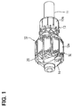
- FIG. 1 is a perspective view showing a structure of an armature incorporating an insulator according to an embodiment of the present invention.
- FIG. 2 is an exploded perspective view of the armature incorporating the insulator according to the embodiment of the present invention.
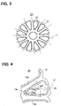
- FIG. 3 is a front view of the insulator according to the embodiment of the present invention.
- FIG. 4 is an enlarged view of a principal portion of the insulator according to the embodiment of the present invention.
- FIG. 5 is an explanatory diagram showing an aligning state of windings by a winding aligning portion according to the embodiment of the present invention.
- FIG. 6 is a cross-sectional and side view showing a structure of a rotary electric machine according to the embodiment of the present invention.
- FIG. 1 is a perspective view showing a structure of an armature incorporating an insulator according to an embodiment of the present invention.
- FIG. 2 is an exploded perspective view of the armature incorporating the insulator according to the embodiment of the present invention.
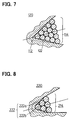
- FIG. 7 is an explanatory diagram showing a winding aligning portion according to a first modified embodiment of the present invention.
- FIG. 8 is an explanatory diagram showing a winding aligning portion according to a second modified embodiment of the present invention.
- FIG. 9 is an explanatory diagram showing a winding aligning portion according to a third modified embodiment of the present invention.
- FIG. 10 is an explanatory diagram showing a winding aligning portion according to a fourth modified embodiment of the present invention.
- FIG. 11 is an explanatory diagram showing winding patterns in using a conventional insulator.
- FIGS. 1 to 6 depict an embodiment of the present invention.
- FIG. 1 is a perspective view showing a structure of an armature incorporating an insulator.
- FIG. 2 is an exploded perspective view of the armature incorporating the insulator.
- FIG. 3 is a front view of the insulator.
- FIG. 4 is an enlarged view of a principal portion of the insulator.
- FIG. 5 is an explanatory diagram showing an aligning state of the windings by a winding aligning portion.
- FIG. 6 is a cross-sectional and side view showing a structure of a rotary electric machine.
- the insulator 40 is shown to be seen from an opposite side to the communicator 13 in FIG. 1.
- the reference numeral 10 in FIG. 1 denotes the armature incorporating the insulator according to the embodiment of the present invention.
- the armature 10 is disposed in a DC rotary electric machine for a vehicular air blower, for example.
- the armature 10 is provided with a rotation shaft 11.
- the rotation shaft 11 is provided with a stack-type armature core 12 having a plurality of salient poles 12a and a commutator 13.
- Each segment 13a of the commutator 13 is connected to a winding 14, which is wound on a plurality of salient poles 12a respectively on a plurality of layers by distribution winding method.
- a diameter of the winding 14 is approximately 0.9 mm.
- the armature core 12 is provided with insulators 20 made of electrical insulating material to secure insulation between the windings 14 and the armature core 12. As shown in FIG. 2, the insulators 20 are formed in a shape approximately similar to the armature core 12 and slightly larger than an outer shape of the armature core 12. A pair of the insulators 20 are disposed on an axial direction of the armature core 12 to interpose the armature core 12 therebetween and are fixed to the armature core 12.
- the insulator 20 has a plurality of slots 21 between the salient poles 12a of the armature core 12 shown in FIG. 1. Many layers of the windings are inserted and disposed in the slot 21.
- the winding aligning portion 22 is formed in each the slot 21 at an inner portion in a radial direction of the insulator 20.
- the winding aligning portion 22 has an approximately V shape formed by two slant faces 22a, 22b connected at an inner portion in the radial direction of the insulator 20 so as to get narrower from an outer side to an inner side in the radial direction of the armature core 12.
- the approximately V-shaped winding aligning portion 22 is formed so that an axis L1 of symmetry thereof is disposed approximately at a middle between the salient poles 12a and that the two slant faces 22a, 22b forming the winding aligning portion 22 meet at 60 degrees. Further, as shown in FIG. 5, the winding aligning portion 22 according to the present embodiment is formed to be able to align the windings 14 of at least two layers at most inner position in the radial direction. Thus, by forming the winding aligning portion 22 configured as described above in the slot 21, the winding 14a on the first layer can be securely positioned in a midsection of the salient poles 12a just by inserting the winding 14a on the first layer in the winding aligning portion 22.
- winding aligning portion 22 it is possible to align the windings 14b-1, 14b-2, 14c-1, 14c-2 and 14c-3 on the second layer and further layer symmetrically with respect to the center axis Lc of the winding aligning portion 22. Thus, is possible to wind the windings 14 to be aligned.
- Winding state of the windings 14 in the slot 21 having the winding aligning portion 22 will be described in detail in the followings. That is, the winding 14a connected to the commutator 13 (refer to FIG. 1) is inserted in the slot 21 and positioned on a center axis Lc of the slot 21 as the winding on the first layer to be in line with the slant faces 22a, 22b of the winding aligning portion 22. Further, the winding 14b-1 inserted in the slot 21 as a first winding on the second layer is wound to be in tight contacts with the winding 14a on the first layer and with the slant face 22b. The winding 14b-2 inserted in the slot 21 as a second winding on the second layer is wound to be in tight contacts with the windings 14a, 14b-1 and the slant face 22a.
- the winding 14c-1 inserted in the slot 21 as a first winding on the third layer is wound to be in tight contact with the winding 14b-1 and the inner wall 21b of the slot 21.
- the winding 14c-2 inserted in the slot 21 as a second winding on the third layer is wound to be in tight contacts with the windings 14b-1, 14b-2, 14c-1 and positioned on the center axis Lc of the slot 21.
- the winding 14c-3 inserted in the slot 21 as a third winding on the third layer is wound to be in tight contacts with windings 14b-2, 14c-2 and the inner wall 21 a of the slot 21.
- the winding aligning portion 22 positions the winding 14a on the first layer on the center of the slot 21, so that the windings 14b-1, 14b-2, 14c-1, 14c-2, 14c-3 are wound to be regularly aligned in the slot 21.
- the insulator 20 As described above, by adopting the insulator 20 according to the present embodiment, it is possible to wind the windings 14 regularly in an aligned manner, thereby preventing dig-in and the like of the windings 14. Thus, the windings 14 are prevented from faulty insulation.
- the insulator 20 is formed so that an center angle ⁇ of the slot 21 (30 degrees in the present embodiment) is smaller than an angle ⁇ (referred to as center angle ⁇ in the following; 60 degrees in the present embodiment) at which the two slant faces 22a, 22b meet in the winding aligning portion 22.
- the center angle ⁇ of the winding aligning portion 22 does not limit the number of the slots 21. That is, in a case that the center angle ⁇ of the slot 21 is formed equal to the center angle ⁇ of the winding aligning portion 22, the number of the slots (that is, the number of the salient poles of the armature core) are excessively limited.
- FIG. 3 for example, in a case that the rotary electric machine should be provided with twelve slots, if the center angle of the slot 21 is set to 60 degrees equal to the center angle of the winding aligning portion 22, only six slots are formed as shown by additional lines L.
- the center angle ⁇ of the slot 21 is formed smaller than the center angle ⁇ of the winding aligning portion 22, so that the number of the slots does not excessively limited. Accordingly, the insulator 20 according to the present embodiment can secure enough number of the slots even if it has a structure to prevent the insufficient insulation in the windings 14.
- the center angle ⁇ of the slots 21 of the insulator 20 are formed smaller than the center angle ⁇ of the winding aligning portion 22.
- the center angle ⁇ of the slots 21 are formed larger than the center angle ⁇ of the winding aligning portion 22.
- the reference numeral 30 in FIG. 6 denotes a DC rotary electric machine used for a vehicular air blower for example.
- the rotary electric machine 30 is constituted to have the above-described armature 10, a brush 31 in slide contact with the armature 10 and a brush supporting apparatus 32 supporting the brush 31 and for supplying electric power from an outer electric power source to the brush 31.
- the armature 10 is enclosed in a yoke housing 33.
- Magnet 34 is disposed on an inner circumferential face of the yoke housing 33.
- the rotary electric machine 30 can prevent insufficient insulation in the windings 14 by being provided with the armature 10 including the insulator 20 as described above.
- the rotary electric machine 30 is improved in its durability relative to conventional ones. Further, by preventing insufficient insulation in the windings 14, it is possible to prevent a disadvantage such as a sudden halt of the armature 10 during rotating operation.
- the present invention has the following advantages.
- the insulator 20 is formed to be able to position the winding 14a on the first layer approximately at the middle between the salient poles 12a among the windings 14a wound on the salient poles 12a.
- the windings 14b-1, 14b-2, 14c-1, 14c-2, 14c-3 on the second layer and beyond in a regularly aligned state. Accordingly, it is possible to prevent the windings 14 from digging and hence to prevent insufficient insulation of the windings 14.
- the insulator 20 according to the present embodiment is formed to have approximately V-shaped winding aligning portion 22 getting narrower from the outer side to the inner side in the radial direction of the armature core 12 approximately at the middle between the salient poles 12a.
- the winding aligning portion 22 is formed such that the two slant faces 22a, 22b meet approximately at 60 degrees. Thus, it is possible to align the windings 14b-1, 14b-2, 14c-1, 14c-2, 14c-3 on the second layer and beyond symmetrically with respect to the center axis of the winding aligning portion 22 as the axis of symmetry.
- the center angle ⁇ (30 degrees in the present embodiment) of the slot 21 is formed smaller than the center angle ⁇ (60 degrees in the present embodiment) of the winding aligning portion.
- the number of the slots 21 is not limited by the center angle ⁇ of the winding aligning portion 22.
- the insulator 20 according to the present embodiment can secure enough number of the slots even if it has a structure capable of preventing insufficient insulation of the windings 14.
- the present embodiment may be modified as follows.
- the winding aligning portion according to the present invention can be formed so that the two slant faces forming the winding aligning portion meet approximately between 45 degrees through 75 degrees (desirably 60 degrees) regardless of the number of the slots.
- the insulator is disposed in the armature with a plurality of the radially-formed salient poles.
- the insulator is characterized in formed to be able to symmetrically align the windings at least on the second layer and beyond at the most inner side in the radial direction of the armature core among the windings wound on the salient poles with respect to the center axis of the slot as the axis of symmetry.
- the insulator by forming the insulator to be able to symmetrically align the windings at least on the second layer and beyond at the most inner side of the armature core among the windings wound on the salient poles with respect to the center axis of the slot as the axis of symmetry, it is possible to wind the windings on the second layer and beyond in a regularly aligned state. Accordingly, it is possible to prevent the windings from digging and hence from insufficient insulation.
Landscapes
- Engineering & Computer Science (AREA)
- Power Engineering (AREA)
- Insulation, Fastening Of Motor, Generator Windings (AREA)
Applications Claiming Priority (3)
| Application Number | Priority Date | Filing Date | Title |
|---|---|---|---|
| JP2002359865 | 2002-12-11 | ||
| JP2002359865 | 2002-12-11 | ||
| PCT/JP2003/015752 WO2004054070A1 (ja) | 2002-12-11 | 2003-12-09 | インシュレータ及び電機子並びに回転電機 |
Publications (3)
| Publication Number | Publication Date |
|---|---|
| EP1575147A1 true EP1575147A1 (de) | 2005-09-14 |
| EP1575147A4 EP1575147A4 (de) | 2006-03-29 |
| EP1575147B1 EP1575147B1 (de) | 2008-01-23 |
Family
ID=32500961
Family Applications (1)
| Application Number | Title | Priority Date | Filing Date |
|---|---|---|---|
| EP03778754A Expired - Lifetime EP1575147B1 (de) | 2002-12-11 | 2003-12-09 | Isolator, armatur und dynamoelektrische maschine |
Country Status (5)
| Country | Link |
|---|---|
| US (1) | US7268457B2 (de) |
| EP (1) | EP1575147B1 (de) |
| CN (1) | CN100401618C (de) |
| DE (1) | DE60318897T2 (de) |
| WO (1) | WO2004054070A1 (de) |
Cited By (1)
| Publication number | Priority date | Publication date | Assignee | Title |
|---|---|---|---|---|
| EP2680412A3 (de) * | 2012-06-29 | 2017-01-18 | NIDEC MOTORS & ACTUATORS GmbH (Germany) | Anordnung von Wicklungsdrähten in einem Rotor eines Elektromotors |
Families Citing this family (7)
| Publication number | Priority date | Publication date | Assignee | Title |
|---|---|---|---|---|
| JP4649951B2 (ja) * | 2004-10-28 | 2011-03-16 | 日本電産株式会社 | モータおよび電機子の製造方法 |
| JP5281822B2 (ja) * | 2008-05-21 | 2013-09-04 | 山洋電気株式会社 | 回転電機用ステータ |
| DE102008059171B4 (de) | 2008-11-24 | 2014-08-28 | Brose Fahrzeugteile GmbH & Co. Kommanditgesellschaft, Würzburg | Antriebsmotor mit integrierter Kühlung |
| CN101764493A (zh) * | 2010-03-10 | 2010-06-30 | 天津大学 | 一种开关磁阻电机 |
| TWI504107B (zh) * | 2010-09-10 | 2015-10-11 | Delta Electronics Inc | 矽鋼片組件及其組裝方法 |
| US9143015B2 (en) | 2012-05-23 | 2015-09-22 | Black & Decker Inc. | Brush holder for a brush assembly for a power tool motor |
| CN108258870A (zh) * | 2016-12-29 | 2018-07-06 | 德昌电机(深圳)有限公司 | 电机及电机磁芯 |
Family Cites Families (16)
| Publication number | Priority date | Publication date | Assignee | Title |
|---|---|---|---|---|
| DE7440605U (de) * | 1974-12-06 | 1976-06-10 | Robert Bosch Gmbh, 7000 Stuttgart | Elektrische maschine |
| JPS5189102U (de) * | 1975-01-10 | 1976-07-16 | ||
| JPS5189102A (de) | 1975-02-03 | 1976-08-04 | ||
| JPS5512760U (de) * | 1978-07-13 | 1980-01-26 | ||
| JPS5512760A (en) | 1978-07-14 | 1980-01-29 | Fuji Electric Co Ltd | Mold electric appliance |
| JPS55166472A (en) | 1979-06-08 | 1980-12-25 | Hitachi Ltd | Armature for commutator rotary machine |
| GB2172444B (en) * | 1985-03-09 | 1988-08-17 | Asmo Co Ltd | Stator for an electric motor |
| DE4403820C2 (de) | 1993-10-11 | 2003-01-30 | Temic Auto Electr Motors Gmbh | Kommutatormotor |
| JP2831264B2 (ja) | 1994-03-07 | 1998-12-02 | アスモ株式会社 | 回転電機 |
| JP3700185B2 (ja) | 1994-10-03 | 2005-09-28 | 株式会社日立製作所 | 電機子 |
| FR2778283A1 (fr) | 1998-04-30 | 1999-11-05 | Valeo Systemes Dessuyage | Joue d'extremite isolante de paquet de toles de ventilateur de vehicule |
| JP2001078382A (ja) * | 1999-06-30 | 2001-03-23 | Asmo Co Ltd | ブラシレスモータ及び車両用空調装置 |
| JP2001286085A (ja) | 2000-03-30 | 2001-10-12 | Asmo Co Ltd | モータのロータ用コアインシュレータ |
| US6580193B2 (en) * | 2000-03-31 | 2003-06-17 | Asmo Co., Ltd. | Rotary electric machine and manufacturing method therefor |
| JP2002272045A (ja) | 2001-03-14 | 2002-09-20 | Moric Co Ltd | 回転界磁型電気機器のステータ構造 |
| JP4815061B2 (ja) | 2001-03-26 | 2011-11-16 | 株式会社ミツバ | 電動モータにおけるアーマチュア構造 |
-
2003
- 2003-12-09 DE DE60318897T patent/DE60318897T2/de not_active Expired - Lifetime
- 2003-12-09 US US10/538,179 patent/US7268457B2/en not_active Expired - Lifetime
- 2003-12-09 EP EP03778754A patent/EP1575147B1/de not_active Expired - Lifetime
- 2003-12-09 WO PCT/JP2003/015752 patent/WO2004054070A1/ja not_active Ceased
- 2003-12-09 CN CNB2003801054969A patent/CN100401618C/zh not_active Expired - Lifetime
Cited By (2)
| Publication number | Priority date | Publication date | Assignee | Title |
|---|---|---|---|---|
| EP2680412A3 (de) * | 2012-06-29 | 2017-01-18 | NIDEC MOTORS & ACTUATORS GmbH (Germany) | Anordnung von Wicklungsdrähten in einem Rotor eines Elektromotors |
| US10122226B2 (en) | 2012-06-29 | 2018-11-06 | Nidec Motors & Actuators (Germany) Gmbh | Arrangement of coil wires in a rotor of an electric motor |
Also Published As
| Publication number | Publication date |
|---|---|
| WO2004054070A1 (ja) | 2004-06-24 |
| CN1723597A (zh) | 2006-01-18 |
| US20060138893A1 (en) | 2006-06-29 |
| DE60318897T2 (de) | 2009-01-22 |
| CN100401618C (zh) | 2008-07-09 |
| US7268457B2 (en) | 2007-09-11 |
| EP1575147A4 (de) | 2006-03-29 |
| DE60318897D1 (de) | 2008-03-13 |
| EP1575147B1 (de) | 2008-01-23 |
Similar Documents
| Publication | Publication Date | Title |
|---|---|---|
| US6856055B2 (en) | Interconnecting ring and wire guide | |
| KR100371159B1 (ko) | 싱크로너스 리럭턴스 모터의 토오크 리플 저감구조 | |
| US10432053B2 (en) | Stator for rotating electrical machine | |
| US20170201135A1 (en) | Stator and rotary machine | |
| US6900572B2 (en) | Stator of rotary electric machine | |
| WO2012137862A1 (ja) | 回転電機の固定子 | |
| EP1575147B1 (de) | Isolator, armatur und dynamoelektrische maschine | |
| US20220294299A1 (en) | Stator and rotary electric machine | |
| US20040201303A1 (en) | Armature of electric rotating machine, electric rotating machine using the same and manufacturing method for armature of electric rotating machine | |
| US6930425B2 (en) | Rotary electric machine stator and method of manufacturing the same | |
| CN114450871B (zh) | 定子和马达 | |
| US20230084091A1 (en) | Motor | |
| US20240388157A1 (en) | Coil assembly, armature, and rotating electrical machine | |
| JP2000060077A (ja) | 回転電機の整流装置 | |
| JP4294831B2 (ja) | 固定子 | |
| JP2006121870A (ja) | モータ装置 | |
| US8914967B2 (en) | Method for producing a distributed lap winding for polyphase systems | |
| US7888836B2 (en) | DC motor with improved wiring connections | |
| JP2000156951A (ja) | 回転電機 | |
| US6774525B2 (en) | Dynamo-electric machine | |
| JP2013158105A (ja) | 回転電機の固定子 | |
| EP0147705A2 (de) | Gleichstrommaschine | |
| JP4114282B2 (ja) | 回転電機およびその製造方法 | |
| WO2016136743A1 (ja) | 回転電機 | |
| JP4354790B2 (ja) | インシュレータ及び電機子並びに回転電機 |
Legal Events
| Date | Code | Title | Description |
|---|---|---|---|
| PUAI | Public reference made under article 153(3) epc to a published international application that has entered the european phase |
Free format text: ORIGINAL CODE: 0009012 |
|
| 17P | Request for examination filed |
Effective date: 20050610 |
|
| AK | Designated contracting states |
Kind code of ref document: A1 Designated state(s): AT BE BG CH CY CZ DE DK EE ES FI FR GB GR HU IE IT LI LU MC NL PT RO SE SI SK TR |
|
| RIN1 | Information on inventor provided before grant (corrected) |
Inventor name: KUBOTA, OSAMU,C/O ASMO CO., LTD. Inventor name: YOSHIKAWA, SHOUICHI,C/O ASMO CO., LTD. Inventor name: NATSUME, YOUSUKE,C/O ASMO CO., LTD. Inventor name: NODA, TAKEO,C/O ASMO CO., LTD. Inventor name: NISHIO, SHIGEO,C/O ASMO CO., LTD. |
|
| A4 | Supplementary search report drawn up and despatched |
Effective date: 20060213 |
|
| RIC1 | Information provided on ipc code assigned before grant |
Ipc: H02K 1/24 20060101ALI20060207BHEP Ipc: H02K 3/34 20060101AFI20040628BHEP |
|
| RBV | Designated contracting states (corrected) |
Designated state(s): DE FR |
|
| 17Q | First examination report despatched |
Effective date: 20060706 |
|
| RTI1 | Title (correction) |
Free format text: INSULATOR, ARMATURE AND DYNAMO-ELECTRIC MACHINE |
|
| GRAP | Despatch of communication of intention to grant a patent |
Free format text: ORIGINAL CODE: EPIDOSNIGR1 |
|
| GRAS | Grant fee paid |
Free format text: ORIGINAL CODE: EPIDOSNIGR3 |
|
| GRAA | (expected) grant |
Free format text: ORIGINAL CODE: 0009210 |
|
| AK | Designated contracting states |
Kind code of ref document: B1 Designated state(s): DE FR |
|
| REF | Corresponds to: |
Ref document number: 60318897 Country of ref document: DE Date of ref document: 20080313 Kind code of ref document: P |
|
| ET | Fr: translation filed | ||
| PLBE | No opposition filed within time limit |
Free format text: ORIGINAL CODE: 0009261 |
|
| STAA | Information on the status of an ep patent application or granted ep patent |
Free format text: STATUS: NO OPPOSITION FILED WITHIN TIME LIMIT |
|
| 26N | No opposition filed |
Effective date: 20081024 |
|
| PGFP | Annual fee paid to national office [announced via postgrant information from national office to epo] |
Ref country code: DE Payment date: 20121205 Year of fee payment: 10 |
|
| PGFP | Annual fee paid to national office [announced via postgrant information from national office to epo] |
Ref country code: FR Payment date: 20130107 Year of fee payment: 10 |
|
| REG | Reference to a national code |
Ref country code: DE Ref legal event code: R119 Ref document number: 60318897 Country of ref document: DE |
|
| REG | Reference to a national code |
Ref country code: DE Ref legal event code: R119 Ref document number: 60318897 Country of ref document: DE Effective date: 20140701 |
|
| REG | Reference to a national code |
Ref country code: FR Ref legal event code: ST Effective date: 20140829 |
|
| PG25 | Lapsed in a contracting state [announced via postgrant information from national office to epo] |
Ref country code: DE Free format text: LAPSE BECAUSE OF NON-PAYMENT OF DUE FEES Effective date: 20140701 |
|
| PG25 | Lapsed in a contracting state [announced via postgrant information from national office to epo] |
Ref country code: FR Free format text: LAPSE BECAUSE OF NON-PAYMENT OF DUE FEES Effective date: 20131231 |