EP1575863B1 - Füllventil, insbesondere zum abfüllen von warmen flüssigkeiten - Google Patents
Füllventil, insbesondere zum abfüllen von warmen flüssigkeiten Download PDFInfo
- Publication number
- EP1575863B1 EP1575863B1 EP03775795A EP03775795A EP1575863B1 EP 1575863 B1 EP1575863 B1 EP 1575863B1 EP 03775795 A EP03775795 A EP 03775795A EP 03775795 A EP03775795 A EP 03775795A EP 1575863 B1 EP1575863 B1 EP 1575863B1
- Authority
- EP
- European Patent Office
- Prior art keywords
- cam
- conduit
- filling
- shaft
- recirculation
- Prior art date
- Legal status (The legal status is an assumption and is not a legal conclusion. Google has not performed a legal analysis and makes no representation as to the accuracy of the status listed.)
- Expired - Lifetime
Links
- 239000007788 liquid Substances 0.000 title claims abstract description 23
- 230000008878 coupling Effects 0.000 description 3
- 238000010168 coupling process Methods 0.000 description 3
- 238000005859 coupling reaction Methods 0.000 description 3
- 241001122767 Theaceae Species 0.000 description 2
- 235000015203 fruit juice Nutrition 0.000 description 2
- 238000012423 maintenance Methods 0.000 description 2
- 230000006837 decompression Effects 0.000 description 1
- 239000000945 filler Substances 0.000 description 1
- 238000010438 heat treatment Methods 0.000 description 1
- 238000009434 installation Methods 0.000 description 1
- 239000000463 material Substances 0.000 description 1
- 238000004321 preservation Methods 0.000 description 1
- 230000001360 synchronised effect Effects 0.000 description 1
Images

Classifications
-
- B—PERFORMING OPERATIONS; TRANSPORTING
- B67—OPENING, CLOSING OR CLEANING BOTTLES, JARS OR SIMILAR CONTAINERS; LIQUID HANDLING
- B67C—CLEANING, FILLING WITH LIQUIDS OR SEMILIQUIDS, OR EMPTYING, OF BOTTLES, JARS, CANS, CASKS, BARRELS, OR SIMILAR CONTAINERS, NOT OTHERWISE PROVIDED FOR; FUNNELS
- B67C3/00—Bottling liquids or semiliquids; Filling jars or cans with liquids or semiliquids using bottling or like apparatus; Filling casks or barrels with liquids or semiliquids
- B67C3/02—Bottling liquids or semiliquids; Filling jars or cans with liquids or semiliquids using bottling or like apparatus
- B67C3/22—Details
- B67C3/26—Filling-heads; Means for engaging filling-heads with bottle necks
- B67C3/2637—Filling-heads; Means for engaging filling-heads with bottle necks comprising a liquid valve opened by relative movement between the container and the filling head
-
- B—PERFORMING OPERATIONS; TRANSPORTING
- B67—OPENING, CLOSING OR CLEANING BOTTLES, JARS OR SIMILAR CONTAINERS; LIQUID HANDLING
- B67C—CLEANING, FILLING WITH LIQUIDS OR SEMILIQUIDS, OR EMPTYING, OF BOTTLES, JARS, CANS, CASKS, BARRELS, OR SIMILAR CONTAINERS, NOT OTHERWISE PROVIDED FOR; FUNNELS
- B67C3/00—Bottling liquids or semiliquids; Filling jars or cans with liquids or semiliquids using bottling or like apparatus; Filling casks or barrels with liquids or semiliquids
- B67C3/02—Bottling liquids or semiliquids; Filling jars or cans with liquids or semiliquids using bottling or like apparatus
- B67C3/06—Bottling liquids or semiliquids; Filling jars or cans with liquids or semiliquids using bottling or like apparatus using counterpressure, i.e. filling while the container is under pressure
- B67C3/14—Bottling liquids or semiliquids; Filling jars or cans with liquids or semiliquids using bottling or like apparatus using counterpressure, i.e. filling while the container is under pressure specially adapted for filling with hot liquids
Definitions
- the present invention relates to a mechanical filling valve, in particular for hot liquids, of the type comprising at least a conduit for the inflow of the liquid into a container and at least an outflow conduit to eject the air present within the container during the filling operation and to allow to recirculate the product at the end of the filling operation.
- a first known prior art solution for maintaining the filling valves at the proper temperature, whilst reducing product recirculation, consists of introducing localised head losses on the outflow conduit.
- a second prior art solution provides for the use of pneumatic devices for opening and closing the delivery conduit, with their operation synchronised with the duration of the filling operation.
- EP-A-0337913 discloses a filling valve as in the preamble of claim 1.
- An object of the present invention is to eliminate the aforesaid drawbacks, making available a mechanical filling valve, in particular for hot liquids, which is able to handle product recirculation, according to productive requirements and to the type of product employed.
- Another object of the present invention is to propose a mechanical filling valve which can be installed on different types of machines, in particular on rotary machines.
- a further aim is to obtain the result expressed above, within the context of a simple, rational and reliable constructive solution.
- the mechanical filling valve is globally designated by the number 1 and finds particular and effective use on rotary filling machines, i.e. those in which the filling valves are positioned on a rotating star, or carrousel.
- the filling valve 1 comprises at least a conduit 2 for the inflow of the filling liquid, for instance tea or fruit juices, to a container (not shown), and an outflow conduit 3 for ejecting the air present inside the container during the filling operation and to allow product recirculation at the end of the filling operation.
- a conduit 2 for the inflow of the filling liquid, for instance tea or fruit juices
- an outflow conduit 3 for ejecting the air present inside the container during the filling operation and to allow product recirculation at the end of the filling operation.
- the inflow conduit 2 and the outflow conduit 3 are respectively connected to a delivery conduit 2a and to a return conduit 2b from/to a tank of the product.
- the filling starts as soon as the container, typically a bottle, is approached to the valve 1 and thrusts a sliding coupling 4 upwards, uncovering a passage port 5 of the inflow conduit 2.
- the container is approached to the valve in a known manner, for instance by means of a plate (not shown) which lifts the container until it brings it in position for filling.
- the valve 1 can also be approached to the container, also in known fashion not shown herein.
- the container is moved away from the valve 1 and the coupling 4 thus closes the passage port 5.
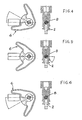
- the filling valve 1 originally comprises mechanical means for managing the recirculation of liquid at the end of the filling operation. Said means are movable between at least a stable open position ( Figure 4) and a stable position of total or partial closure ( Figures 6 and 5) of the inflow conduit 2.
- Recirculation takes place in two different manners, depending on whether the container is present or not. If the container is present, the liquid recirculates in the outflow conduit 3, since, upon exiting the passage port 5, it is deviated by the walls of the mouth of the container (which is thus completely filled). Vice versa, in the absence of the container, the liquid coming from the inflow conduit 2 is deviated into the outflow conduit 3 thanks to the presence of the coupling 4 which obstructs the passage port 5.
- the mechanical means for managing the recirculation comprise a cam 6 whereto is integrally connected a shaft 7. At one end of the shaft 7 is in turn integrally connected a shutter 8, which intercepts the inflow conduit 3 and is immersed in the flow of liquid.
- the means for managing recirculation further comprise a link rod 10 having a first end 10a inserted in a cavity 6a of the cam 6 and a second end 10b inserted in a cavity 6b of a support assembly 11 of the shaft 7.
- the cavities 6a and 6b are elastically pressed against each other, preferably by means of a helical spring 12.
- the means for managing recirculation are also provided with at least an abutment element 13 able to maintain the cam 6 stably positioned in a predetermined operative position.
- the cam 6, together with the abutment element 13, enable to obtain an actuation of the shutter 8 between stable operative configurations, corresponding to the opening and/or (total or partial) closure of the inflow conduit 2.
- the abutment element 13 comprises a piston 14 inserted in a cavity 15 of the support assembly 11 of the shaft 7 and an elastic element, preferably a helical spring 16, operatively active on the piston, to maintain it pressed against the cam 6.
- the means for managing liquid recirculation comprise a plurality of abutment elements (not shown) integral with a frame of a filling machine, which activate the rotation of the cam 6 by impact (consequently controlling the motion of the shutter 8). Specifically, it is the motion of the carrousel itself, whereon the filling valves are located, which causes the cam 6 to impact against the abutment elements.
- the abutment elements will be positioned on the frame of the filling machine in such a way as to cause the opening and/or the (total or partial) closure of the shutter 8, according to the angular positioning of the carrousel.
- the shutter allows alternatively fully to open, shut or throttle the inflow conduit 2, thereby managing product recirculation.
- the invention achieves important advantages.
- such a filling valve allows to manage recirculation according to the productivity and operating conditions of the installation.
- the ability to stop recirculation at any time facilitates maintenance operations and prevents the loss of liquid in case of sudden failures.
- Another advantage is represented by the fact that such a filling valve, having no pneumatic device for actuating the shutter, can easily be installed on rotary machines.
Landscapes
- Filling Of Jars Or Cans And Processes For Cleaning And Sealing Jars (AREA)
- Basic Packing Technique (AREA)
Claims (2)
- Füllventil (1) für Flüssigkeiten, insbesondere für warme Flüssigkeiten, umfassend:zumindest einen Kanal (2) zum Zuführen der Flüssigkeit zu einem Behälter;zumindest einen Abfuhrkanal (3) zum Ausstossen von Luft aus dem Behälterinneren während des Abfüllvorgangs und zur Ermöglichung einer Rückführung der Flüssigkeit nach Beendigung des Abfüllvorgangs;mechanische Mittel zum Bewerkstelligen der Rückführung von Flüssigkeit nach Beendigung des Abfüllvorgangs, wobei diese mechanischen Mittel umfasseneinen Nocken (6);eine fest mit dem Nocken (6) verbundene Welle (7); zumindest ein fest mit der Welle (7) verbundenes und den Zufuhrkanal (2) verschliessendes Schliessorgan (8), das bei Gebrauch mit der Flüssigkeit in Berührung kommt;Mittel zum Betätigen des Nockens (6), welche eine Drehung desselben um einen vorbestimmten Winkel zwischen mindestens einer stabilen, der Öffnung des Zufuhrkanals (2) entsprechenden Öffnungsposition und einer stabilen, der vollständigen oder teilweisen Schliessung des Zufuhrkanals (2) durch das Schliessorgan (8) entsprechenden Position, dadurch gekennzeichnet, dass die mechanischen Mittel ferner umfassen:eine Lageranordnung für die Welle (7); zumindest eine Verbindungsstange (10), die ein erstes, in eine Ausnehmung (6a) des Nockens (6) eingreifendes Ende (10a) und ein zweites, in eine Ausnehmung (6b) der genannten Lageranordnung für die Welle (7) eingreifendes Ende (10b) aufweist, wobei der Nocken (6), das zweite Ende (10b) und die Verbindungsstange (10) elastisch gegeneinander gepresst werden;zumindest ein Anschlagelement (13), das den Nocken (6) stabil in einer vorbestimmten Betriebsanordnung hält,wobei durch den Nocken (6) und das Anschlagelement (13) eine Betätigung des Schliessorgans (8) zwischen stabilen, zumindest der Öffnung und der Schliessung des Abfuhrkanals (2) entsprechenden Betriebsanordnungen ermöglichen.
- Füllventil nach Anspruch 1, dadurch gekennzeichnet, dass das Anschlagelement (13) umfasst:zumindest einen in eine zylinderförmige Ausnehmung (15) der Lageranordnung (11) für die Welle (7) eingebrachten Kolben (14);zumindest ein elastisches Element (16), das betrieblich auf den Kolben (14) wirkt, um diesen gegen den Nocken (6) gepresst zu halten.
Applications Claiming Priority (3)
| Application Number | Priority Date | Filing Date | Title |
|---|---|---|---|
| ITPR20020080 | 2002-12-23 | ||
| IT000080A ITPR20020080A1 (it) | 2002-12-23 | 2002-12-23 | Valvola riempitrice, in particolare per liquidi caldi. |
| PCT/IT2003/000663 WO2004056693A1 (en) | 2002-12-23 | 2003-10-27 | Filling valve, in particular for hot liquids |
Publications (2)
| Publication Number | Publication Date |
|---|---|
| EP1575863A1 EP1575863A1 (de) | 2005-09-21 |
| EP1575863B1 true EP1575863B1 (de) | 2007-12-19 |
Family
ID=32676883
Family Applications (1)
| Application Number | Title | Priority Date | Filing Date |
|---|---|---|---|
| EP03775795A Expired - Lifetime EP1575863B1 (de) | 2002-12-23 | 2003-10-27 | Füllventil, insbesondere zum abfüllen von warmen flüssigkeiten |
Country Status (8)
| Country | Link |
|---|---|
| EP (1) | EP1575863B1 (de) |
| CN (1) | CN1726161A (de) |
| AT (1) | ATE381512T1 (de) |
| AU (1) | AU2003283814A1 (de) |
| BR (1) | BR0316727A (de) |
| DE (1) | DE60318248D1 (de) |
| IT (1) | ITPR20020080A1 (de) |
| WO (1) | WO2004056693A1 (de) |
Cited By (1)
| Publication number | Priority date | Publication date | Assignee | Title |
|---|---|---|---|---|
| DE102008057752A1 (de) * | 2008-11-17 | 2010-05-20 | Khs Ag | Füllelement sowie Füllsystem mit einem solchen Füllelement |
Families Citing this family (6)
| Publication number | Priority date | Publication date | Assignee | Title |
|---|---|---|---|---|
| DE102004004331B3 (de) * | 2004-01-29 | 2005-09-15 | Khs Maschinen- Und Anlagenbau Ag | Verfahren zum Heißabfüllen eines flüssigen Füllgutes in Flaschen oder dergleichen Behälter sowie Füllmaschine zum Durchführen des Verfahrens |
| CN100460310C (zh) * | 2005-09-08 | 2009-02-11 | 中国轻工业机械总公司南京轻工业机械厂 | 热灌装阀 |
| IT1402577B1 (it) * | 2010-10-25 | 2013-09-13 | Cortellazzi | Valvola di riempimento a gravita' per prodotti imbottigliati a caldo con sistema di ricircolo del prodotto da imbottigliare sia a valvola aperta che a valvola chiusa. |
| IT1403550B1 (it) * | 2011-01-14 | 2013-10-31 | Corfill Internat S R L | Valvola di riempimento |
| US10696434B2 (en) * | 2011-01-31 | 2020-06-30 | Khs Gmbh | Method and device for producing containers which are filled with a liquid filling substance |
| CN103318825A (zh) * | 2013-05-30 | 2013-09-25 | 常熟市喆宏机械科技有限公司 | 填充头 |
Family Cites Families (4)
| Publication number | Priority date | Publication date | Assignee | Title |
|---|---|---|---|---|
| US3756290A (en) * | 1971-12-02 | 1973-09-04 | K Cleland | Volumetric filler system for flexible resilient bottles |
| AR210313A1 (es) * | 1974-06-06 | 1977-07-29 | Crown Cork S A I C | Valvulas llenadoras de liquidos carbonatados |
| ES2006386A6 (es) * | 1988-03-21 | 1989-04-16 | Perrier Iberica | Perfeccionamientos en cabezales llenadores de botellas a presion. |
| IT1254638B (it) * | 1992-02-20 | 1995-09-28 | Cobert Spa | Dispositivo a valvola di riempimento per liquidi non gasati funzionante per gravita', con sistema di autolivellamento a leggera pressione di gas, per macchine imbottigliatrici |
-
2002
- 2002-12-23 IT IT000080A patent/ITPR20020080A1/it unknown
-
2003
- 2003-10-27 AU AU2003283814A patent/AU2003283814A1/en not_active Abandoned
- 2003-10-27 BR BR0316727-5A patent/BR0316727A/pt not_active IP Right Cessation
- 2003-10-27 EP EP03775795A patent/EP1575863B1/de not_active Expired - Lifetime
- 2003-10-27 AT AT03775795T patent/ATE381512T1/de not_active IP Right Cessation
- 2003-10-27 WO PCT/IT2003/000663 patent/WO2004056693A1/en not_active Ceased
- 2003-10-27 CN CN200380106172.7A patent/CN1726161A/zh active Pending
- 2003-10-27 DE DE60318248T patent/DE60318248D1/de not_active Expired - Lifetime
Cited By (1)
| Publication number | Priority date | Publication date | Assignee | Title |
|---|---|---|---|---|
| DE102008057752A1 (de) * | 2008-11-17 | 2010-05-20 | Khs Ag | Füllelement sowie Füllsystem mit einem solchen Füllelement |
Also Published As
| Publication number | Publication date |
|---|---|
| BR0316727A (pt) | 2005-10-18 |
| AU2003283814A1 (en) | 2004-07-14 |
| DE60318248D1 (de) | 2008-01-31 |
| ITPR20020080A1 (it) | 2004-06-24 |
| ATE381512T1 (de) | 2008-01-15 |
| CN1726161A (zh) | 2006-01-25 |
| EP1575863A1 (de) | 2005-09-21 |
| WO2004056693A1 (en) | 2004-07-08 |
Similar Documents
| Publication | Publication Date | Title |
|---|---|---|
| JP4873866B2 (ja) | 液状充填物を瓶またはそのような容器に高温充填する方法とこの方法を実施する充填機 | |
| US7753093B2 (en) | Tipless can filling valve | |
| US9221666B2 (en) | Dispensing appliance provided with a hinged hood | |
| US8496031B2 (en) | Tipless can filling valve | |
| KR100235817B1 (ko) | 분배 밸브 조립체 | |
| EP1575863B1 (de) | Füllventil, insbesondere zum abfüllen von warmen flüssigkeiten | |
| EP3581542B1 (de) | Füllventil und füllmaschine zum füllen von behältern | |
| US20140305541A1 (en) | Container Filling Valve | |
| US12116259B2 (en) | Dual-mode fluid connector having rotatable element and supporting two different operating modes | |
| EP1862230B1 (de) | Vorrichtung zum Waschen / Sterilisieren / Ausblasen von Behältern | |
| EP1190985B1 (de) | Getränkespender für Haushaltkühlschränke | |
| US9139312B2 (en) | Tipless can filling valve | |
| EP3640197B1 (de) | Füllmaschine zur heissfüllung | |
| CN219134599U (zh) | 一种粘性液体灌装机的防滴漏装置及包括其的灌装机 | |
| JP7379483B2 (ja) | 泡制御付きビールタップ | |
| US9145288B2 (en) | Tipless can filling valve | |
| JP4282255B2 (ja) | 回転式無菌充填機 | |
| KR200153681Y1 (ko) | 냉장고의 급수펌프장치 | |
| CN109153555A (zh) | 用于将加压的泡沫和碳酸饮料倾倒至容器中的自动装置 | |
| US2064378A (en) | Bottle filler snifter |
Legal Events
| Date | Code | Title | Description |
|---|---|---|---|
| PUAI | Public reference made under article 153(3) epc to a published international application that has entered the european phase |
Free format text: ORIGINAL CODE: 0009012 |
|
| 17P | Request for examination filed |
Effective date: 20050428 |
|
| AK | Designated contracting states |
Kind code of ref document: A1 Designated state(s): AT BE BG CH CY CZ DE DK EE ES FI FR GB GR HU IE IT LI LU MC NL PT RO SE SI SK TR |
|
| AX | Request for extension of the european patent |
Extension state: AL LT LV MK |
|
| RIN1 | Information on inventor provided before grant (corrected) |
Inventor name: BOSELLI, MASSIMO Inventor name: ARBELTI, LUCA |
|
| DAX | Request for extension of the european patent (deleted) | ||
| GRAP | Despatch of communication of intention to grant a patent |
Free format text: ORIGINAL CODE: EPIDOSNIGR1 |
|
| GRAS | Grant fee paid |
Free format text: ORIGINAL CODE: EPIDOSNIGR3 |
|
| GRAA | (expected) grant |
Free format text: ORIGINAL CODE: 0009210 |
|
| AK | Designated contracting states |
Kind code of ref document: B1 Designated state(s): AT BE BG CH CY CZ DE DK EE ES FI FR GB GR HU IE IT LI LU MC NL PT RO SE SI SK TR |
|
| REG | Reference to a national code |
Ref country code: GB Ref legal event code: FG4D |
|
| REG | Reference to a national code |
Ref country code: IE Ref legal event code: FG4D |
|
| REG | Reference to a national code |
Ref country code: CH Ref legal event code: EP |
|
| REF | Corresponds to: |
Ref document number: 60318248 Country of ref document: DE Date of ref document: 20080131 Kind code of ref document: P |
|
| PG25 | Lapsed in a contracting state [announced via postgrant information from national office to epo] |
Ref country code: CH Free format text: LAPSE BECAUSE OF FAILURE TO SUBMIT A TRANSLATION OF THE DESCRIPTION OR TO PAY THE FEE WITHIN THE PRESCRIBED TIME-LIMIT Effective date: 20071219 Ref country code: SE Free format text: LAPSE BECAUSE OF FAILURE TO SUBMIT A TRANSLATION OF THE DESCRIPTION OR TO PAY THE FEE WITHIN THE PRESCRIBED TIME-LIMIT Effective date: 20080319 Ref country code: LI Free format text: LAPSE BECAUSE OF FAILURE TO SUBMIT A TRANSLATION OF THE DESCRIPTION OR TO PAY THE FEE WITHIN THE PRESCRIBED TIME-LIMIT Effective date: 20071219 |
|
| PG25 | Lapsed in a contracting state [announced via postgrant information from national office to epo] |
Ref country code: SI Free format text: LAPSE BECAUSE OF FAILURE TO SUBMIT A TRANSLATION OF THE DESCRIPTION OR TO PAY THE FEE WITHIN THE PRESCRIBED TIME-LIMIT Effective date: 20071219 Ref country code: FI Free format text: LAPSE BECAUSE OF FAILURE TO SUBMIT A TRANSLATION OF THE DESCRIPTION OR TO PAY THE FEE WITHIN THE PRESCRIBED TIME-LIMIT Effective date: 20071219 Ref country code: NL Free format text: LAPSE BECAUSE OF FAILURE TO SUBMIT A TRANSLATION OF THE DESCRIPTION OR TO PAY THE FEE WITHIN THE PRESCRIBED TIME-LIMIT Effective date: 20071219 |
|
| NLV1 | Nl: lapsed or annulled due to failure to fulfill the requirements of art. 29p and 29m of the patents act | ||
| REG | Reference to a national code |
Ref country code: CH Ref legal event code: PL |
|
| PG25 | Lapsed in a contracting state [announced via postgrant information from national office to epo] |
Ref country code: AT Free format text: LAPSE BECAUSE OF FAILURE TO SUBMIT A TRANSLATION OF THE DESCRIPTION OR TO PAY THE FEE WITHIN THE PRESCRIBED TIME-LIMIT Effective date: 20071219 |
|
| PG25 | Lapsed in a contracting state [announced via postgrant information from national office to epo] |
Ref country code: CZ Free format text: LAPSE BECAUSE OF FAILURE TO SUBMIT A TRANSLATION OF THE DESCRIPTION OR TO PAY THE FEE WITHIN THE PRESCRIBED TIME-LIMIT Effective date: 20071219 Ref country code: ES Free format text: LAPSE BECAUSE OF FAILURE TO SUBMIT A TRANSLATION OF THE DESCRIPTION OR TO PAY THE FEE WITHIN THE PRESCRIBED TIME-LIMIT Effective date: 20080330 |
|
| PG25 | Lapsed in a contracting state [announced via postgrant information from national office to epo] |
Ref country code: SK Free format text: LAPSE BECAUSE OF FAILURE TO SUBMIT A TRANSLATION OF THE DESCRIPTION OR TO PAY THE FEE WITHIN THE PRESCRIBED TIME-LIMIT Effective date: 20071219 Ref country code: BE Free format text: LAPSE BECAUSE OF FAILURE TO SUBMIT A TRANSLATION OF THE DESCRIPTION OR TO PAY THE FEE WITHIN THE PRESCRIBED TIME-LIMIT Effective date: 20071219 Ref country code: RO Free format text: LAPSE BECAUSE OF FAILURE TO SUBMIT A TRANSLATION OF THE DESCRIPTION OR TO PAY THE FEE WITHIN THE PRESCRIBED TIME-LIMIT Effective date: 20071219 |
|
| PG25 | Lapsed in a contracting state [announced via postgrant information from national office to epo] |
Ref country code: PT Free format text: LAPSE BECAUSE OF FAILURE TO SUBMIT A TRANSLATION OF THE DESCRIPTION OR TO PAY THE FEE WITHIN THE PRESCRIBED TIME-LIMIT Effective date: 20080519 |
|
| EN | Fr: translation not filed | ||
| PLBE | No opposition filed within time limit |
Free format text: ORIGINAL CODE: 0009261 |
|
| STAA | Information on the status of an ep patent application or granted ep patent |
Free format text: STATUS: NO OPPOSITION FILED WITHIN TIME LIMIT |
|
| PG25 | Lapsed in a contracting state [announced via postgrant information from national office to epo] |
Ref country code: DK Free format text: LAPSE BECAUSE OF FAILURE TO SUBMIT A TRANSLATION OF THE DESCRIPTION OR TO PAY THE FEE WITHIN THE PRESCRIBED TIME-LIMIT Effective date: 20071219 Ref country code: DE Free format text: LAPSE BECAUSE OF FAILURE TO SUBMIT A TRANSLATION OF THE DESCRIPTION OR TO PAY THE FEE WITHIN THE PRESCRIBED TIME-LIMIT Effective date: 20080320 |
|
| 26N | No opposition filed |
Effective date: 20080922 |
|
| PG25 | Lapsed in a contracting state [announced via postgrant information from national office to epo] |
Ref country code: GR Free format text: LAPSE BECAUSE OF FAILURE TO SUBMIT A TRANSLATION OF THE DESCRIPTION OR TO PAY THE FEE WITHIN THE PRESCRIBED TIME-LIMIT Effective date: 20080320 |
|
| PG25 | Lapsed in a contracting state [announced via postgrant information from national office to epo] |
Ref country code: FR Free format text: LAPSE BECAUSE OF FAILURE TO SUBMIT A TRANSLATION OF THE DESCRIPTION OR TO PAY THE FEE WITHIN THE PRESCRIBED TIME-LIMIT Effective date: 20081010 Ref country code: EE Free format text: LAPSE BECAUSE OF FAILURE TO SUBMIT A TRANSLATION OF THE DESCRIPTION OR TO PAY THE FEE WITHIN THE PRESCRIBED TIME-LIMIT Effective date: 20071219 Ref country code: BG Free format text: LAPSE BECAUSE OF FAILURE TO SUBMIT A TRANSLATION OF THE DESCRIPTION OR TO PAY THE FEE WITHIN THE PRESCRIBED TIME-LIMIT Effective date: 20080319 |
|
| PG25 | Lapsed in a contracting state [announced via postgrant information from national office to epo] |
Ref country code: MC Free format text: LAPSE BECAUSE OF NON-PAYMENT OF DUE FEES Effective date: 20081031 |
|
| GBPC | Gb: european patent ceased through non-payment of renewal fee |
Effective date: 20081027 |
|
| PG25 | Lapsed in a contracting state [announced via postgrant information from national office to epo] |
Ref country code: CY Free format text: LAPSE BECAUSE OF FAILURE TO SUBMIT A TRANSLATION OF THE DESCRIPTION OR TO PAY THE FEE WITHIN THE PRESCRIBED TIME-LIMIT Effective date: 20071219 |
|
| PG25 | Lapsed in a contracting state [announced via postgrant information from national office to epo] |
Ref country code: IT Free format text: LAPSE BECAUSE OF NON-PAYMENT OF DUE FEES Effective date: 20081027 |
|
| PG25 | Lapsed in a contracting state [announced via postgrant information from national office to epo] |
Ref country code: IE Free format text: LAPSE BECAUSE OF NON-PAYMENT OF DUE FEES Effective date: 20081027 |
|
| PG25 | Lapsed in a contracting state [announced via postgrant information from national office to epo] |
Ref country code: GB Free format text: LAPSE BECAUSE OF NON-PAYMENT OF DUE FEES Effective date: 20081027 |
|
| PG25 | Lapsed in a contracting state [announced via postgrant information from national office to epo] |
Ref country code: HU Free format text: LAPSE BECAUSE OF FAILURE TO SUBMIT A TRANSLATION OF THE DESCRIPTION OR TO PAY THE FEE WITHIN THE PRESCRIBED TIME-LIMIT Effective date: 20080620 Ref country code: LU Free format text: LAPSE BECAUSE OF NON-PAYMENT OF DUE FEES Effective date: 20081027 |
|
| PG25 | Lapsed in a contracting state [announced via postgrant information from national office to epo] |
Ref country code: TR Free format text: LAPSE BECAUSE OF FAILURE TO SUBMIT A TRANSLATION OF THE DESCRIPTION OR TO PAY THE FEE WITHIN THE PRESCRIBED TIME-LIMIT Effective date: 20071219 |