EP1576343B1 - Module de pesee pourvu d'un dispositif de depoussierage - Google Patents
Module de pesee pourvu d'un dispositif de depoussierage Download PDFInfo
- Publication number
- EP1576343B1 EP1576343B1 EP03796003A EP03796003A EP1576343B1 EP 1576343 B1 EP1576343 B1 EP 1576343B1 EP 03796003 A EP03796003 A EP 03796003A EP 03796003 A EP03796003 A EP 03796003A EP 1576343 B1 EP1576343 B1 EP 1576343B1
- Authority
- EP
- European Patent Office
- Prior art keywords
- gas
- dust
- weighing module
- housing
- weighing
- Prior art date
- Legal status (The legal status is an assumption and is not a legal conclusion. Google has not performed a legal analysis and makes no representation as to the accuracy of the status listed.)
- Expired - Lifetime
Links
- 238000005303 weighing Methods 0.000 title claims abstract description 45
- 239000000428 dust Substances 0.000 claims abstract description 33
- 238000000034 method Methods 0.000 claims abstract description 9
- 238000009825 accumulation Methods 0.000 claims 2
- 230000007717 exclusion Effects 0.000 abstract 1
- 238000005259 measurement Methods 0.000 abstract 1
- 239000007789 gas Substances 0.000 description 57
- 230000005540 biological transmission Effects 0.000 description 18
- 238000000151 deposition Methods 0.000 description 3
- 238000004140 cleaning Methods 0.000 description 2
- 230000008021 deposition Effects 0.000 description 2
- 238000007789 sealing Methods 0.000 description 2
- 230000015572 biosynthetic process Effects 0.000 description 1
- 238000004891 communication Methods 0.000 description 1
- 238000011109 contamination Methods 0.000 description 1
- 238000009826 distribution Methods 0.000 description 1
- 230000000694 effects Effects 0.000 description 1
- 230000035515 penetration Effects 0.000 description 1
- 239000002244 precipitate Substances 0.000 description 1
- 230000001681 protective effect Effects 0.000 description 1
- 230000001105 regulatory effect Effects 0.000 description 1
Images


Classifications
-
- G—PHYSICS
- G01—MEASURING; TESTING
- G01G—WEIGHING
- G01G21/00—Details of weighing apparatus
- G01G21/30—Means for preventing contamination by dust
Definitions
- the invention relates to a balance, in particular a weighing module, with a load cell on all sides surrounding housing, with a force transmission member which is connectable to a load bearing device, wherein the transmission member passes through an opening of a housing wall and with a vertically movable part of the load cell in a rigid connection stands.
- Such scales or weighing modules are preferably used in industrial environments, for example as so-called belt weighers, wherein the weighing module is arranged, for example, below a conveyor belt in order to weigh objects transported by the latter.
- the environment in which such a weighing module is installed very dusty.
- the weighing module must be surrounded by a protective housing and, in particular in the region of openings of the housing, be protected by suitable measures against the ingress of dust.
- Particularly critical is the implementation of the power transmission member serving housing opening, as these must be known to be mandatory in order to connect a load bearing with the vertically movable part of the load cell can.
- various measures are proposed to prevent the ingress of dirt into the interior of a balance housing.
- EP-A-1 146 322 discloses a balance with a sealing detent which consists of an elastic, arbitrarily expandable and reducible device for abutment between a stationary part connected to the balance housing and a part moving through the load opposite the balance housing. This device releases the moving part of the scale during the weighing process and keeps it locked during the rest of the time. At the same time, the lock has a certain sealing effect, which is particularly efficient when the elastic means between the power transmission member and the balance housing is arranged. Thus, the penetration of dust into the interior of the balance housing largely avoided.
- Another measure, as disclosed in the same document, is to provide the power transmission member with a cup-shaped cover and optionally provide them as part of a labyrinth seal.
- DE 85 08 424 U1 discloses an upper shell scale in which the interior of the housing can be externally ventilated.
- the housing has a connecting piece, through which a gas stream can be introduced into the interior of the housing.
- the weighing pan is supported via a connecting piece through an opening in the upper part of the housing onto a load receiver disposed within the housing.
- the housing On the bottom, the housing also has a breakthrough, with the load receptor extends into this breakthrough.
- these provisions may be sufficient to protect against the ingress of dust, but there is the problem that is relatively small by the cup-shaped cover, the distance between the fixed housing of the weighing module and the vertically movable power transmission member together with cover and so there is the danger that forms a dust bridge, so to speak, as a mechanical connection, between the two parts.
- This may be dust from the air or weighing goods falling from the load support.
- a dust bridge can already produce a mechanical short circuit and thus falsify the weighing result.
- a balance in particular a weighing module with a housing surrounding a load cell on all sides, has a vertically movable force transmission member which is connectable to a load bearing device, wherein the force transmission member passes through a passage opening of a housing wall and is in a rigid connection with a vertically movable part of the load cell , It there is provided with a gas supply device for dust removal, which has a at least one flow channel having gas distributor to prevent dust deposition between the fixed housing and the vertically movable power transmission member. The at least one flow channel communicates with a gas inlet and has a gas outlet for generating a gas flow directed away from the movable part of the balance.
- the device for dust removal on a gas distributor which is one or more parts, in particular two parts, configured, and which consists of a distributor ring and a connectable with this lid.
- the gas distributor has at least one annular flow channel for a gas under overpressure, in particular compressed air.
- the gas distributor consists of two flow channels communicating with one another, wherein a first flow channel communicates with a gas inlet and a second flow channel has a gas outlet.
- this gas outlet consists of nozzles directed away from the moving part of the balance or, alternatively, is designed in the form of a gap surrounding the device for removing dust.
- the gas distributor may be arranged substantially within the balance housing or be placed on the balance housing from the outside.
- the invention can be a method for preventing dust deposition between the fixed housing and the vertically movable Implement power transmission element in a balance, in particular a weighing module, in which a gas flow both during the weighing process, as well as outside of the weighing operation is directed away from the movable part of the balance.
- the gas stream is continuous or alternatively in the form of pulsed gas ejections.
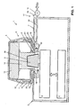
- FIG. 1 schematically shows a weighing module 1, for example a belt weigher to be arranged below a weighing section of a conveyor belt, which has a tightly sealed, easily cleanable housing 2.
- a known load cell 3 is arranged, which is connected to a weighing electronics 4.
- the power transmission member 6 is an integral part of the movable part of the balance.
- the pot-shaped cap 5 rests on a hub 13 connected to a part 14, which is placed on the cone-shaped force transducer 9.
- the hub part 14 has a corresponding cone-shaped receiving recess 36.
- the cap 5 has a sleeve-shaped outer ring 10 and a tubular inner ring 12 with different diameters, which are arranged coaxially to one another and laterally delimit an intermediate cavity. Concentric with the opening 8 of the housing 2 is an in cooperation with the concentric rings 10 and 12, a labyrinth seal against the ingress of dust into the balance housing 2 forming intermediate ring 11 between the outer ring 10 and the inner ring 12 on the housing 2 is arranged.
- the cap 5 can be lifted for the purpose of cleaning. This is especially necessary in dusty environment. However, since, as described above, even during the weighing operation a lot of dust on the balance housing 2 can precipitate, so that this forms a mechanical bridge between the non-movable balance housing 2 and the vertically movable power transmission member 6, in particular the cap 5, is the balance 1 is provided with a device for dust removal 15, which is arranged in the embodiment shown in Figure 1 mainly within the balance housing 2.
- the device for removing dust 15 has a gas distributor 16, which is fixedly connected to the underside of the housing wall 7 of the balance housing 2, and a gas supply device 17, which passes through the housing 2 passing gas, in particular compressed air, the gas distributor 16 from below.
- the gas pressure or that of the compressed air can be regulated via the valve 18.
- the gas distributor 16 has along its inner circumference a recess which forms a flow channel 19. In this, the gas or compressed air passes through a gas inlet 20.
- the compressed air from the flow channel 19 passes directly into a gas outlet 23, as a kind of gap, which is arranged parallel to the housing wall 7, and which blows under the cover 5 through the compressed air located in the flow channel 19 in the horizontal direction to the outside.
- a gas outlet 23 as a kind of gap, which is arranged parallel to the housing wall 7, and which blows under the cover 5 through the compressed air located in the flow channel 19 in the horizontal direction to the outside.
- this embodiment of the device for removing dust 15 is integrated excellently into the balance housing 2.
- the supply of gas or compressed air is manually or automatically controlled by means of a valve 18, via a pressure line 34.
- the valve 18 has a manually operated or automatic device 35, which allows gas via the pressure line 34 in the flow channel 19th to introduce under a predefined pressure.
- FIG. 2 shows a weighing module with another embodiment of a device according to the invention for removing dust 115. Parts which are not changed in their design in comparison with FIG. 1 are identified by the same reference numeral.
- This device for dust removal 115 can be mounted from the top to the top 7 of the balance housing 2 and is therefore modular, since the gas distributor 116 can be attached afterwards and can also be removed again at any time.
- the gas distributor 116 is formed in two parts and consists of a distributor ring 124 and a cover 125.
- first flow channel 119 is provided with a part of a first flow channel 119 forming special bulge, which comes to lie exactly above the gas inlet 120 with mounted on the distributor ring 124 lid 125 and which is adapted to introduce the gas or the compressed air into the circular first flow channel 119.
- the first flow channel 119 is connected to a second flow channel 126, to which the gas outlet 123, in turn configured as a gap encompassing the entire circumference of the gas distributor 116, follows.
- the embodiment shown in Figure 2 has a simplified form of a cap 105.
- Such a two-part gas distributor 116 in addition to its improved mounting options still has the advantage of being particularly easy to disassemble for cleaning purposes.
- FIG. 3 shows a gas distributor 216, in three-dimensional representation, in a third embodiment. It in turn consists of a distributor ring 224 and a cover 225 and has the same as that described with reference to FIG 2 Embodiment, two preferably arranged one above the other flow channels (only one of which is visible in the figure).
- the first flow channel 219 is set in each case a circular recess formed in the lower distributor ring and in the lid. This forms in the assembled state, the first flow channel, which is connected to the second flow channel 226 via a plurality of preferably circular gas passage openings 227 (see also Figure 5), through which the gas, or the compressed air flows from the first into the second flow channel.
- the compressed air in turn passes through a gas outlet, in the form of an annular gap, which forms when mounted on the upper housing wall 7 gas distributor 216 between the housing wall 7 and lower distributor ring 224.
- the dimensions of the gap are at a thickness of 0.1 to 0.5 mm in order to maintain a sufficiently high flow pressure can.
- both the cover 225 and the distributor ring 224 of the gas distributor can be seen in the top view.
- the gas passage openings 227 connecting the first flow channel 219 to the second flow channel 226 (see FIG. 4) can be clearly seen here.
- For the attachment of the cover 225 on the distributor ring 224 serve screws which are screwed through the through holes 228 in the threaded holes 229 in the cover 225.
- the through-bores 230 in the cover 225 and the through-holes 231 in the distributor ring 224 are provided for fastening the gas distributor 216 to the upper housing wall 7.
- the opening 232 in the distributor ring 224 is part of the gas inlet and opens when the lid is mounted in a bulge 233, from where the compressed air enters the first flow channel 219.
- the second flow channel 226 (see FIG. 4) is connected to the at least one housing wall 7 in such a way that either a narrow gap is present through which the air flows outward in a predominantly radial direction.
- nozzles which are directed radially outward may also be arranged on the second flow channel and act as a gas outlet.
- one-piece or multi-part, in particular two-part, embodiments of a gas distributor are conceivable, such having a flow channel or two flow channels communicating with one another.
- a device according to the invention for dust removal is not necessarily arranged on the upper housing wall. Rather, it is in each case arranged where the passage for the power transmission member is attached to the balance, so for example below, in the case of an underfloor scale, or on the side for a lateral passage of the power transmission member through the balance housing.
Landscapes
- Physics & Mathematics (AREA)
- General Physics & Mathematics (AREA)
- Measuring Volume Flow (AREA)
- Cleaning In General (AREA)
- Structure Of Belt Conveyors (AREA)
- Framework For Endless Conveyors (AREA)
- Filtering Of Dispersed Particles In Gases (AREA)
- Brushes (AREA)
- Prevention Of Fouling (AREA)
- Cleaning By Liquid Or Steam (AREA)
- Cleaning Implements For Floors, Carpets, Furniture, Walls, And The Like (AREA)
- Air Conditioning Control Device (AREA)
Claims (13)
- Module de pesée (1) avec un carter (2) entourant de tous côtés une cellule de pesée (3), avec un élément de transmission de force (6) mobile verticalement, qui peut être lié à un dispositif de support de charge, l'élément de transmission de force (6) passant à travers une ouverture (8) d'une paroi (7) de carter et étant en liaison fixe avec une partie mobile verticalement de la cellule de pesée (3), et un dispositif doté d'un dispositif d'arrivée de gaz (17) pour l'enlèvement de poussière (15, 115) étant présent entre le carter (2) fixe et l'élément de transmission de force (6) mobile verticalement afin d'éviter un dépôt de poussière, caractérisé en ce que le dispositif d'enlèvement de poussière (15, 115) dispose d'un répartiteur de gaz (16, 116, 216) présentant au moins un canal d'écoulement (19, 119, 219, 126, 226), le au moins un canal d'écoulement étant en liaison avec une entrée de gaz (20, 120) et présentant une sortie de gaz (23, 123) pour générer un flux de gaz dirigé à partir de la partie mobile de la balance.
- Module de pesée (1) selon la revendication 1, caractérisé en ce que le répartiteur de gaz (116, 216) est conçu en plusieurs parties, en particulier en deux parties, et comprend une bague de répartition (124, 224) et un couvercle (125, 225) pouvant être relié à cette bague.
- Module de pesée (1) selon la revendication 1 ou 2, caractérisé en ce que le répartiteur de gaz (16) présente au moins un canal d'écoulement (19) de forme annulaire pour un gaz se trouvant sous surpression.
- Module de pesée (1) selon la revendication 1, 2 ou 3, caractérisé en ce que le répartiteur de gaz (16, 116, 216) se compose de deux canaux d'écoulement (119, 219, 126, 226) en liaison entre eux, un premier canal d'écoulement (119, 219) étant en liaison avec une entrée de gaz (20, 120) et un second canal d'écoulement (126, 226) présentant une sortie de gaz (123).
- Module de pesée (1) selon l'une quelconque des revendications 1 à 4, caractérisé en ce qu'une sortie de gaz (23, 123) est présente, laquelle se compose de buses dirigées à partir de la partie mobile de la balance (1).
- Module de pesée (1) selon l'une quelconque des revendications 1 à 4, caractérisé en ce qu'une sortie de gaz (23, 123) est présente, qui est conçue sous la forme d'une fente entourant le dispositif d'enlèvement de poussière (15).
- Module de pesée (1) selon l'une quelconque des revendications 1 à 6, caractérisé en ce que le répartiteur de gaz (16) est disposé sensiblement à l'intérieur du carter de balance (2).
- Module de pesée (1) selon l'une quelconque des revendications 1 à 6, caractérisé en ce que le répartiteur de gaz (116, 216) est posé par l'extérieur sur le carter de balance (2).
- Module de pesée (1) selon l'une quelconque des revendications 1 à 8, caractérisé en ce que le dispositif d'enlèvement de poussière (15, 115) est conçu pour former un flux de gaz continu.
- Module de pesée (1) selon l'une quelconque des revendications 1 à 8, caractérisé en ce que le dispositif d'enlèvement de poussière (15, 115) est conçu pour la formation d'un flux de gaz sous la forme d'expulsions de gaz pulsées.
- Procédé pour éviter un dépôt de poussière entre le carter (2) fixe et l'élément de transmission de force (6) mobile verticalement sur une balance (1), respectivement un module de pesée (1), avec un dispositif selon l'une quelconque des revendications 1 à 10, caractérisé en ce qu'un flux de gaz intervenant aussi bien pendant l'opération de pesée qu'en dehors de l'opération de pesée est dirigé à partir de la partie mobile de la balance.
- Procédé selon la revendication 11, caractérisé en ce que le flux de gaz s'effectue de façon continue.
- Procédé selon la revendication 11, caractérisé en ce que le flux de gaz s'effectue sous la forme d'expulsions de gaz pulsées.
Applications Claiming Priority (3)
| Application Number | Priority Date | Filing Date | Title |
|---|---|---|---|
| DE10253601A DE10253601B4 (de) | 2002-11-15 | 2002-11-15 | Wägemodul mit Vorrichtung zur Staubentfernung |
| DE10253601 | 2002-11-15 | ||
| PCT/EP2003/050804 WO2004046667A1 (fr) | 2002-11-15 | 2003-11-07 | Module de pesee pourvu d'un dispositif de depoussierage |
Publications (3)
| Publication Number | Publication Date |
|---|---|
| EP1576343A1 EP1576343A1 (fr) | 2005-09-21 |
| EP1576343B1 true EP1576343B1 (fr) | 2007-02-14 |
| EP1576343B2 EP1576343B2 (fr) | 2018-07-11 |
Family
ID=32185791
Family Applications (1)
| Application Number | Title | Priority Date | Filing Date |
|---|---|---|---|
| EP03796003.6A Expired - Lifetime EP1576343B2 (fr) | 2002-11-15 | 2003-11-07 | Module de pesee pourvu d'un dispositif de depoussierage |
Country Status (6)
| Country | Link |
|---|---|
| US (1) | US7112750B2 (fr) |
| EP (1) | EP1576343B2 (fr) |
| AT (1) | ATE354077T1 (fr) |
| AU (1) | AU2003298276A1 (fr) |
| DE (2) | DE10253601B4 (fr) |
| WO (1) | WO2004046667A1 (fr) |
Cited By (3)
| Publication number | Priority date | Publication date | Assignee | Title |
|---|---|---|---|---|
| EP2278285A1 (fr) | 2009-07-23 | 2011-01-26 | Mettler-Toledo AG | Capteur de charge pouvant être relié |
| DE102007058330C5 (de) * | 2007-12-04 | 2014-05-08 | Sartorius Lab Instruments Gmbh & Co. Kg | Waage |
| EP3153830A1 (fr) | 2015-10-06 | 2017-04-12 | Mettler-Toledo GmbH | Support de charge ayant un dispositif de verrouillage |
Families Citing this family (11)
| Publication number | Priority date | Publication date | Assignee | Title |
|---|---|---|---|---|
| DE202008009407U1 (de) * | 2008-07-14 | 2008-09-25 | Wipotec Wiege- Und Positioniersysteme Gmbh | Labyrinthdichtung |
| EP2159554A1 (fr) * | 2008-08-29 | 2010-03-03 | Mettler-Toledo AG | Procédé de surveillance d'état d'un dispositif de mesure de force, dispositif de mesure de force et module de mesure de force |
| DE102008056515B4 (de) | 2008-11-08 | 2013-03-14 | Sartorius Weighing Technology Gmbh | Wägezelle und Verfahren zum Abdichten einer Wägezelle |
| DE102008056514C5 (de) * | 2008-11-08 | 2016-03-03 | Sartorius Lab Instruments Gmbh & Co. Kg | Wägezelle und Verfahren zum Temperieren einer Wägezelle |
| DE102009013545B4 (de) * | 2009-03-19 | 2013-02-21 | Wipotec Wiege- Und Positioniersysteme Gmbh | Dichtmechanismus |
| PL2574900T3 (pl) * | 2011-09-30 | 2015-11-30 | Mettler Toledo Gmbh | Przyrząd pomiarowy do grawimetrycznego wyznaczania wilgotności |
| JP6164613B2 (ja) * | 2014-01-24 | 2017-07-19 | 株式会社タニタ | 秤 |
| JP6486777B2 (ja) * | 2015-06-19 | 2019-03-20 | アンリツインフィビス株式会社 | 重量測定装置 |
| DE202015104676U1 (de) * | 2015-09-03 | 2015-11-23 | Leifheit Ag | Küchenwaage |
| CN112067101B (zh) * | 2020-07-29 | 2021-12-21 | 新兴铸管股份有限公司 | 一种具有除尘功能的汽车衡称台 |
| US20250354855A1 (en) * | 2021-12-17 | 2025-11-20 | A&D Company, Limited | Waterproof mechanism for weighing apparatus |
Family Cites Families (19)
| Publication number | Priority date | Publication date | Assignee | Title |
|---|---|---|---|---|
| DE633106C (de) * | 1933-06-01 | 1936-07-20 | Sachsenberg Akt Ges Geb | Diaphragma |
| FR998837A (fr) * | 1949-10-17 | 1952-01-23 | Vandenbosch E | Perfectionnements apportés aux appareils de pesage fixes, notamment aux bascules |
| US3722895A (en) † | 1970-12-30 | 1973-03-27 | Dravo Corp | Sealing device |
| DE7730465U1 (de) † | 1977-10-01 | 1978-02-23 | Sartorius-Werke Gmbh (Und Vormals Goettinger Praezisionswaagenfabrik Gmbh), 3400 Goettingen | Windschutz fuer oberschalige feinwaagen |
| DE7913203U1 (de) † | 1979-05-08 | 1980-05-14 | Sartorius Gmbh, 3400 Goettingen | Waage |
| DE3205799A1 (de) * | 1982-02-18 | 1983-08-25 | Sartorius GmbH, 3400 Göttingen | Oberschalige elektronische waage |
| DE8508424U1 (de) * | 1985-03-21 | 1986-04-24 | Sartorius GmbH, 3400 Göttingen | Oberschalige Waage |
| DE3800941A1 (de) † | 1988-01-15 | 1989-07-27 | Avt Anlagen Verfahrenstech | Dichtungsanordnung |
| DE8805063U1 (de) * | 1988-04-16 | 1989-08-17 | Sartorius GmbH, 3400 Göttingen | Belüftungsvorrichtung für eine Waage |
| DE68905195T2 (de) † | 1988-10-12 | 1993-06-17 | Setra Systems Inc | Feuchtigkeitsregelungssystem fuer eine waage. |
| DE4309373A1 (de) † | 1993-03-23 | 1994-09-29 | Bolz Alfred Gmbh Co Kg | Verfahren und Vorrichtung zum Abfüllen von gefährlichen Stoffen in Behälter |
| US5402672A (en) * | 1993-08-24 | 1995-04-04 | North Atlantic Equipment Sales, Inc. | Microwave oven moisture analyzer |
| CH689650A5 (de) * | 1995-04-04 | 1999-07-30 | Mettler Toledo Gmbh | In einem Gehaeuse eingebauter Trockner. |
| DE20018310U1 (de) * | 1999-11-08 | 2001-03-29 | Sartorius AG, 37075 Göttingen | Analysenwaage zur Wägung von elektrostatisch aufgeladenem Wägegut |
| DE10017528A1 (de) * | 2000-04-10 | 2001-10-18 | Mettler Toledo Gmbh | Waage mit dichtender Arretierung |
| DE10022099B4 (de) * | 2000-05-08 | 2012-11-15 | Mettler-Toledo Ag | Kühlung für ein Messgerät zur gravimetrischen Feuchtigkeitsbestimmung |
| DE10025712C2 (de) * | 2000-05-25 | 2003-11-13 | Mettler Toledo Gmbh | Waage mit Überdruckgehäuse |
| DE10101366A1 (de) * | 2001-01-13 | 2002-08-08 | Itw Gema Ag | Sprühbeschichtungs-Pulverzentrum |
| JP4005025B2 (ja) † | 2001-11-02 | 2007-11-07 | ボーグワーナー・インコーポレーテッド | 一体化されたバイパスを備えた被制御ターボ過給機 |
-
2002
- 2002-11-15 DE DE10253601A patent/DE10253601B4/de not_active Expired - Lifetime
-
2003
- 2003-11-07 EP EP03796003.6A patent/EP1576343B2/fr not_active Expired - Lifetime
- 2003-11-07 WO PCT/EP2003/050804 patent/WO2004046667A1/fr not_active Ceased
- 2003-11-07 DE DE50306543T patent/DE50306543D1/de not_active Expired - Lifetime
- 2003-11-07 AT AT03796003T patent/ATE354077T1/de not_active IP Right Cessation
- 2003-11-07 AU AU2003298276A patent/AU2003298276A1/en not_active Abandoned
-
2005
- 2005-05-13 US US11/128,540 patent/US7112750B2/en not_active Expired - Lifetime
Cited By (5)
| Publication number | Priority date | Publication date | Assignee | Title |
|---|---|---|---|---|
| DE102007058330C5 (de) * | 2007-12-04 | 2014-05-08 | Sartorius Lab Instruments Gmbh & Co. Kg | Waage |
| US8912455B2 (en) | 2007-12-04 | 2014-12-16 | Sartorius Lab Instruments Gmbh & Co. Kg | Scale with an adjusting device configured as a fluid drive actuator imparting gearless translational motion to place the scale in a washing-down position or in a transport position |
| EP2278285A1 (fr) | 2009-07-23 | 2011-01-26 | Mettler-Toledo AG | Capteur de charge pouvant être relié |
| US8426753B2 (en) | 2009-07-23 | 2013-04-23 | Mettler-Toledo Ag | Gravimetric measuring instrument with releasable load receiver |
| EP3153830A1 (fr) | 2015-10-06 | 2017-04-12 | Mettler-Toledo GmbH | Support de charge ayant un dispositif de verrouillage |
Also Published As
| Publication number | Publication date |
|---|---|
| EP1576343B2 (fr) | 2018-07-11 |
| US7112750B2 (en) | 2006-09-26 |
| ATE354077T1 (de) | 2007-03-15 |
| AU2003298276A1 (en) | 2004-06-15 |
| US20050217902A1 (en) | 2005-10-06 |
| WO2004046667A1 (fr) | 2004-06-03 |
| DE10253601A1 (de) | 2004-05-27 |
| EP1576343A1 (fr) | 2005-09-21 |
| DE50306543D1 (de) | 2007-03-29 |
| DE10253601B4 (de) | 2013-11-07 |
Similar Documents
| Publication | Publication Date | Title |
|---|---|---|
| EP1576343B2 (fr) | Module de pesee pourvu d'un dispositif de depoussierage | |
| EP3153830B1 (fr) | Support de charge ayant un dispositif de verrouillage | |
| EP0337132A2 (fr) | Dispositif pour amener des matières pulvérulentes à un dispositif de distribution | |
| CH657453A5 (de) | Oberschalige elektronische waage. | |
| EP0660074B1 (fr) | Tête de mesure photoélectrique | |
| EP0794035B1 (fr) | Dispositif de contrôle automtique du support d'une pièce à usiner | |
| DE3716047A1 (de) | Verfahren und einrichtung zum betreiben einer fuellvorrichtung fuer staubfoermiges oder koerniges gut | |
| DE3918470C2 (fr) | ||
| EP1294509A1 (fr) | Panier de coulee pour couler un metal en fusion dans une machine de coulee en bande | |
| DE3802147C2 (de) | Verfahren und Vorrichtung zur Qualitätsüberwachung von durch Spritz- oder Druckgießmaschinen hergestellten Formteilen | |
| DE10330788A1 (de) | Waage mit Windschutzelement | |
| DE10115097A1 (de) | Einrichtung zur Verhinderung eines Vortex-Effekts im Auslaufbereich eines metallurgischen Schmelzgefäßes | |
| DE102017123018B4 (de) | Aktive führungserfassungsvorrichtung | |
| EP1856489B1 (fr) | Balance de verification | |
| DE2929500C2 (de) | Abschirmvorrichtung für einen Gießstrahl aus flüssigem Metall | |
| DE10041433C2 (de) | Vorrichtung zur Messung eines Masse-Stromes | |
| CH633106A5 (en) | Protective device for top-pan precision balances | |
| DE3510199A1 (de) | Beschichtungseinrichtung zum automatischen spruehbeschichten von gegenstaenden | |
| EP3670984A1 (fr) | Dispositif de modification d'un flux de produit en vrac, en particulier dispositif de dosage et dispositif de raccordement de conduites | |
| DE102008046179A1 (de) | Optoelektronischer Sensor und Verfahren zum Anbringen | |
| EP2006022A1 (fr) | Agencement de traitement d'échantillons pour un dispositif de dosage des liquides | |
| AT408965B (de) | Einrichtung zum verschliessen eines abstichloches eines metallurgischen gefässes | |
| DE3106790C2 (de) | Einrichtung zum Abschirmen eines Offenbereiches zwischen einem Industrieofen, insbesondere Konverter, und einem Ofenkamin mittels eines Sperrgasvorhanges | |
| EP1296123B1 (fr) | Installation transmetteur montée sur un conduit d'une installation de traitement | |
| EP0470397A1 (fr) | Appareil de mesure des dimensions d'une pièce |
Legal Events
| Date | Code | Title | Description |
|---|---|---|---|
| PUAI | Public reference made under article 153(3) epc to a published international application that has entered the european phase |
Free format text: ORIGINAL CODE: 0009012 |
|
| 17P | Request for examination filed |
Effective date: 20050613 |
|
| AK | Designated contracting states |
Kind code of ref document: A1 Designated state(s): AT BE BG CH CY CZ DE DK EE ES FI FR GB GR HU IE IT LI LU MC NL PT RO SE SI SK TR |
|
| AX | Request for extension of the european patent |
Extension state: AL LT LV MK |
|
| DAX | Request for extension of the european patent (deleted) | ||
| GRAP | Despatch of communication of intention to grant a patent |
Free format text: ORIGINAL CODE: EPIDOSNIGR1 |
|
| RAP1 | Party data changed (applicant data changed or rights of an application transferred) |
Owner name: METTLER-TOLEDO AG |
|
| GRAS | Grant fee paid |
Free format text: ORIGINAL CODE: EPIDOSNIGR3 |
|
| GRAA | (expected) grant |
Free format text: ORIGINAL CODE: 0009210 |
|
| AK | Designated contracting states |
Kind code of ref document: B1 Designated state(s): AT BE BG CH CY CZ DE DK EE ES FI FR GB GR HU IE IT LI LU MC NL PT RO SE SI SK TR |
|
| PG25 | Lapsed in a contracting state [announced via postgrant information from national office to epo] |
Ref country code: NL Free format text: LAPSE BECAUSE OF FAILURE TO SUBMIT A TRANSLATION OF THE DESCRIPTION OR TO PAY THE FEE WITHIN THE PRESCRIBED TIME-LIMIT Effective date: 20070214 Ref country code: SI Free format text: LAPSE BECAUSE OF FAILURE TO SUBMIT A TRANSLATION OF THE DESCRIPTION OR TO PAY THE FEE WITHIN THE PRESCRIBED TIME-LIMIT Effective date: 20070214 Ref country code: IE Free format text: LAPSE BECAUSE OF FAILURE TO SUBMIT A TRANSLATION OF THE DESCRIPTION OR TO PAY THE FEE WITHIN THE PRESCRIBED TIME-LIMIT Effective date: 20070214 Ref country code: FI Free format text: LAPSE BECAUSE OF FAILURE TO SUBMIT A TRANSLATION OF THE DESCRIPTION OR TO PAY THE FEE WITHIN THE PRESCRIBED TIME-LIMIT Effective date: 20070214 Ref country code: DK Free format text: LAPSE BECAUSE OF FAILURE TO SUBMIT A TRANSLATION OF THE DESCRIPTION OR TO PAY THE FEE WITHIN THE PRESCRIBED TIME-LIMIT Effective date: 20070214 |
|
| REG | Reference to a national code |
Ref country code: GB Ref legal event code: FG4D Free format text: NOT ENGLISH |
|
| REG | Reference to a national code |
Ref country code: CH Ref legal event code: EP |
|
| REF | Corresponds to: |
Ref document number: 50306543 Country of ref document: DE Date of ref document: 20070329 Kind code of ref document: P |
|
| REG | Reference to a national code |
Ref country code: IE Ref legal event code: FG4D Free format text: LANGUAGE OF EP DOCUMENT: GERMAN |
|
| PG25 | Lapsed in a contracting state [announced via postgrant information from national office to epo] |
Ref country code: SE Free format text: LAPSE BECAUSE OF FAILURE TO SUBMIT A TRANSLATION OF THE DESCRIPTION OR TO PAY THE FEE WITHIN THE PRESCRIBED TIME-LIMIT Effective date: 20070514 |
|
| PG25 | Lapsed in a contracting state [announced via postgrant information from national office to epo] |
Ref country code: BG Free format text: LAPSE BECAUSE OF EXPIRATION OF PROTECTION Effective date: 20070515 |
|
| PG25 | Lapsed in a contracting state [announced via postgrant information from national office to epo] |
Ref country code: ES Free format text: LAPSE BECAUSE OF FAILURE TO SUBMIT A TRANSLATION OF THE DESCRIPTION OR TO PAY THE FEE WITHIN THE PRESCRIBED TIME-LIMIT Effective date: 20070525 |
|
| GBT | Gb: translation of ep patent filed (gb section 77(6)(a)/1977) |
Effective date: 20070508 |
|
| PG25 | Lapsed in a contracting state [announced via postgrant information from national office to epo] |
Ref country code: PT Free format text: LAPSE BECAUSE OF FAILURE TO SUBMIT A TRANSLATION OF THE DESCRIPTION OR TO PAY THE FEE WITHIN THE PRESCRIBED TIME-LIMIT Effective date: 20070716 |
|
| NLV1 | Nl: lapsed or annulled due to failure to fulfill the requirements of art. 29p and 29m of the patents act | ||
| ET | Fr: translation filed | ||
| REG | Reference to a national code |
Ref country code: IE Ref legal event code: FD4D |
|
| PLBI | Opposition filed |
Free format text: ORIGINAL CODE: 0009260 |
|
| PG25 | Lapsed in a contracting state [announced via postgrant information from national office to epo] |
Ref country code: SK Free format text: LAPSE BECAUSE OF FAILURE TO SUBMIT A TRANSLATION OF THE DESCRIPTION OR TO PAY THE FEE WITHIN THE PRESCRIBED TIME-LIMIT Effective date: 20070214 |
|
| PLAX | Notice of opposition and request to file observation + time limit sent |
Free format text: ORIGINAL CODE: EPIDOSNOBS2 |
|
| 26 | Opposition filed |
Opponent name: WIPOTEC WIEGE- UND POSITIONIERSYSTEME GMBH Effective date: 20071114 |
|
| PG25 | Lapsed in a contracting state [announced via postgrant information from national office to epo] |
Ref country code: RO Free format text: LAPSE BECAUSE OF FAILURE TO SUBMIT A TRANSLATION OF THE DESCRIPTION OR TO PAY THE FEE WITHIN THE PRESCRIBED TIME-LIMIT Effective date: 20070214 Ref country code: CZ Free format text: LAPSE BECAUSE OF FAILURE TO SUBMIT A TRANSLATION OF THE DESCRIPTION OR TO PAY THE FEE WITHIN THE PRESCRIBED TIME-LIMIT Effective date: 20070214 |
|
| PLAF | Information modified related to communication of a notice of opposition and request to file observations + time limit |
Free format text: ORIGINAL CODE: EPIDOSCOBS2 |
|
| PG25 | Lapsed in a contracting state [announced via postgrant information from national office to epo] |
Ref country code: GR Free format text: LAPSE BECAUSE OF FAILURE TO SUBMIT A TRANSLATION OF THE DESCRIPTION OR TO PAY THE FEE WITHIN THE PRESCRIBED TIME-LIMIT Effective date: 20070515 Ref country code: IT Free format text: LAPSE BECAUSE OF FAILURE TO SUBMIT A TRANSLATION OF THE DESCRIPTION OR TO PAY THE FEE WITHIN THE PRESCRIBED TIME-LIMIT Effective date: 20070214 |
|
| BERE | Be: lapsed |
Owner name: METTLER-TOLEDO A.G. Effective date: 20071130 |
|
| PG25 | Lapsed in a contracting state [announced via postgrant information from national office to epo] |
Ref country code: MC Free format text: LAPSE BECAUSE OF NON-PAYMENT OF DUE FEES Effective date: 20071130 |
|
| PLBB | Reply of patent proprietor to notice(s) of opposition received |
Free format text: ORIGINAL CODE: EPIDOSNOBS3 |
|
| PG25 | Lapsed in a contracting state [announced via postgrant information from national office to epo] |
Ref country code: BE Free format text: LAPSE BECAUSE OF NON-PAYMENT OF DUE FEES Effective date: 20071130 |
|
| PG25 | Lapsed in a contracting state [announced via postgrant information from national office to epo] |
Ref country code: EE Free format text: LAPSE BECAUSE OF FAILURE TO SUBMIT A TRANSLATION OF THE DESCRIPTION OR TO PAY THE FEE WITHIN THE PRESCRIBED TIME-LIMIT Effective date: 20070214 |
|
| PG25 | Lapsed in a contracting state [announced via postgrant information from national office to epo] |
Ref country code: AT Free format text: LAPSE BECAUSE OF NON-PAYMENT OF DUE FEES Effective date: 20071107 |
|
| PG25 | Lapsed in a contracting state [announced via postgrant information from national office to epo] |
Ref country code: CY Free format text: LAPSE BECAUSE OF FAILURE TO SUBMIT A TRANSLATION OF THE DESCRIPTION OR TO PAY THE FEE WITHIN THE PRESCRIBED TIME-LIMIT Effective date: 20070214 |
|
| PG25 | Lapsed in a contracting state [announced via postgrant information from national office to epo] |
Ref country code: LU Free format text: LAPSE BECAUSE OF NON-PAYMENT OF DUE FEES Effective date: 20071107 |
|
| PG25 | Lapsed in a contracting state [announced via postgrant information from national office to epo] |
Ref country code: HU Free format text: LAPSE BECAUSE OF FAILURE TO SUBMIT A TRANSLATION OF THE DESCRIPTION OR TO PAY THE FEE WITHIN THE PRESCRIBED TIME-LIMIT Effective date: 20070815 Ref country code: TR Free format text: LAPSE BECAUSE OF FAILURE TO SUBMIT A TRANSLATION OF THE DESCRIPTION OR TO PAY THE FEE WITHIN THE PRESCRIBED TIME-LIMIT Effective date: 20070214 |
|
| PLCK | Communication despatched that opposition was rejected |
Free format text: ORIGINAL CODE: EPIDOSNREJ1 |
|
| APBM | Appeal reference recorded |
Free format text: ORIGINAL CODE: EPIDOSNREFNO |
|
| APBP | Date of receipt of notice of appeal recorded |
Free format text: ORIGINAL CODE: EPIDOSNNOA2O |
|
| APAH | Appeal reference modified |
Free format text: ORIGINAL CODE: EPIDOSCREFNO |
|
| APBQ | Date of receipt of statement of grounds of appeal recorded |
Free format text: ORIGINAL CODE: EPIDOSNNOA3O |
|
| REG | Reference to a national code |
Ref country code: CH Ref legal event code: PCOW Free format text: NEW ADDRESS: IM LANGACHER 44, 8606 GREIFENSEE (CH) |
|
| REG | Reference to a national code |
Ref country code: FR Ref legal event code: PLFP Year of fee payment: 13 |
|
| REG | Reference to a national code |
Ref country code: CH Ref legal event code: PFA Owner name: METTLER-TOLEDO GMBH, CH Free format text: FORMER OWNER: METTLER-TOLEDO AG, CH |
|
| RAP2 | Party data changed (patent owner data changed or rights of a patent transferred) |
Owner name: METTLER-TOLEDO GMBH |
|
| REG | Reference to a national code |
Ref country code: FR Ref legal event code: PLFP Year of fee payment: 14 |
|
| REG | Reference to a national code |
Ref country code: DE Ref legal event code: R081 Ref document number: 50306543 Country of ref document: DE Owner name: METTLER-TOLEDO GMBH, CH Free format text: FORMER OWNER: METTLER-TOLEDO AG, GREIFENSEE, CH |
|
| REG | Reference to a national code |
Ref country code: FR Ref legal event code: PLFP Year of fee payment: 15 |
|
| APBU | Appeal procedure closed |
Free format text: ORIGINAL CODE: EPIDOSNNOA9O |
|
| REG | Reference to a national code |
Ref country code: FR Ref legal event code: CJ Effective date: 20180409 |
|
| PUAH | Patent maintained in amended form |
Free format text: ORIGINAL CODE: 0009272 |
|
| STAA | Information on the status of an ep patent application or granted ep patent |
Free format text: STATUS: PATENT MAINTAINED AS AMENDED |
|
| 27A | Patent maintained in amended form |
Effective date: 20180711 |
|
| AK | Designated contracting states |
Kind code of ref document: B2 Designated state(s): AT BE BG CH CY CZ DE DK EE ES FI FR GB GR HU IE IT LI LU MC NL PT RO SE SI SK TR |
|
| REG | Reference to a national code |
Ref country code: DE Ref legal event code: R102 Ref document number: 50306543 Country of ref document: DE |
|
| REG | Reference to a national code |
Ref country code: CH Ref legal event code: AELC |
|
| REG | Reference to a national code |
Ref country code: FR Ref legal event code: PLFP Year of fee payment: 16 |
|
| PGFP | Annual fee paid to national office [announced via postgrant information from national office to epo] |
Ref country code: FR Payment date: 20191029 Year of fee payment: 17 |
|
| PGFP | Annual fee paid to national office [announced via postgrant information from national office to epo] |
Ref country code: GB Payment date: 20191029 Year of fee payment: 17 |
|
| GBPC | Gb: european patent ceased through non-payment of renewal fee |
Effective date: 20201107 |
|
| PG25 | Lapsed in a contracting state [announced via postgrant information from national office to epo] |
Ref country code: FR Free format text: LAPSE BECAUSE OF NON-PAYMENT OF DUE FEES Effective date: 20201130 |
|
| PG25 | Lapsed in a contracting state [announced via postgrant information from national office to epo] |
Ref country code: GB Free format text: LAPSE BECAUSE OF NON-PAYMENT OF DUE FEES Effective date: 20201107 |
|
| PGFP | Annual fee paid to national office [announced via postgrant information from national office to epo] |
Ref country code: DE Payment date: 20221128 Year of fee payment: 20 |
|
| PGFP | Annual fee paid to national office [announced via postgrant information from national office to epo] |
Ref country code: CH Payment date: 20221123 Year of fee payment: 20 |
|
| REG | Reference to a national code |
Ref country code: DE Ref legal event code: R071 Ref document number: 50306543 Country of ref document: DE |
|
| REG | Reference to a national code |
Ref country code: CH Ref legal event code: PL |