EP1576805B1 - Appareil d'eclairage et procede d'eclairage pour appareil d'imagerie - Google Patents
Appareil d'eclairage et procede d'eclairage pour appareil d'imagerie Download PDFInfo
- Publication number
- EP1576805B1 EP1576805B1 EP03768310A EP03768310A EP1576805B1 EP 1576805 B1 EP1576805 B1 EP 1576805B1 EP 03768310 A EP03768310 A EP 03768310A EP 03768310 A EP03768310 A EP 03768310A EP 1576805 B1 EP1576805 B1 EP 1576805B1
- Authority
- EP
- European Patent Office
- Prior art keywords
- leds
- imaging
- light emitting
- period
- light
- Prior art date
- Legal status (The legal status is an assumption and is not a legal conclusion. Google has not performed a legal analysis and makes no representation as to the accuracy of the status listed.)
- Expired - Lifetime
Links
Images


Classifications
-
- H—ELECTRICITY
- H04—ELECTRIC COMMUNICATION TECHNIQUE
- H04N—PICTORIAL COMMUNICATION, e.g. TELEVISION
- H04N23/00—Cameras or camera modules comprising electronic image sensors; Control thereof
- H04N23/56—Cameras or camera modules comprising electronic image sensors; Control thereof provided with illuminating means
-
- H—ELECTRICITY
- H04—ELECTRIC COMMUNICATION TECHNIQUE
- H04N—PICTORIAL COMMUNICATION, e.g. TELEVISION
- H04N23/00—Cameras or camera modules comprising electronic image sensors; Control thereof
-
- G—PHYSICS
- G03—PHOTOGRAPHY; CINEMATOGRAPHY; ANALOGOUS TECHNIQUES USING WAVES OTHER THAN OPTICAL WAVES; ELECTROGRAPHY; HOLOGRAPHY
- G03B—APPARATUS OR ARRANGEMENTS FOR TAKING PHOTOGRAPHS OR FOR PROJECTING OR VIEWING THEM; APPARATUS OR ARRANGEMENTS EMPLOYING ANALOGOUS TECHNIQUES USING WAVES OTHER THAN OPTICAL WAVES; ACCESSORIES THEREFOR
- G03B15/00—Special procedures for taking photographs; Apparatus therefor
- G03B15/02—Illuminating scene
- G03B15/03—Combinations of cameras with lighting apparatus; Flash units
- G03B15/04—Combinations of cameras with non-electronic flash apparatus; Non-electronic flash units
Definitions
- the present invention relates to an illumination apparatus and an imaging apparatus.
- a digital camera imaging a photo-object by an image pickup device such as a CCD (Charge Coupled Device), and storing the image of the photo-object in various recording media has a function for taking a moving picture, in addition to a function of taking a still picture.
- a format for storing a moving picture a MJPEG (Motion Joint Photographic Experts Group) format is frequently employed.
- a photo-object is imaged successively, for example, once in every 33 msecs by exposing the image pickup device in accordance with a certain frame rate, and a plurality of frames obtained by imaging the photo-object are compressed and stored.
- a built-in strobe is so structured as to emit a strobe light (auxiliary light) by using a discharge tube such as a xenon lamp or the like as a light source and by causing the discharge tube to discharge by a high voltage current from a power source of the camera in which the built-in strobe is contained.
- a discharge tube such as a xenon lamp or the like
- LED light emitting diode
- the LED light source mounted to a video camera of an inspection system is described in US 5,010,412 .
- the LED light source is formed of a plurality of light emitting diodes which simultaneously emit light in an intermittent manner. Specifically, all the light emitting diodes are synchronously switched on and off.
- the frequency for driving the diodes is adjustable by a user such that the LED light source may provide a strobe light which corresponds to a frequency of a rotating or an oscillating machine part. Accordingly, the illuminated machine part can be monitored in a selected position, even while in motion.
- the user may adjust the brightness of the LED light source by setting the duty cycle of the LED driving.
- the patent application WO 02/098141 A2 describes a LED lighting device for a still photo camera.
- the device comprises red, blue, and green LEDs, and emulates a source of white light due to superposition of the three colors.
- the LEDs sequentially emit light, wherein each of the LEDs emits light exactly one time. As the LEDs are individually driven one after another, the instantaneous load of the battery in the camera is reduced.
- an illumination apparatus utilizing an LED as a light source as described above has a problem. That is, if one tries to increase the amount of auxiliary light obtained from such an illumination apparatus, many LEDs are required, and the amount of consumed electricity increases in accordance with the increase in the number of LEDs.
- the present invention was made in view of the above circumstance, and an object of the present invention is therefore to provide an illumination apparatus, imaging apparatus and irradiation method with a light source structure constituted by a light emitting diode, wherein the amount of auxiliary light can be increased without increasing the amount of consumed electricity. This is achieved by the subject matter of the independent claims.
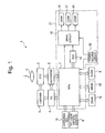
- FIG. 1 is a block diagram showing a structure of an electronic still camera according to a first exemplary embodiment.
- the electronic still camera 1 comprises a photographing lens 2, a CCD (Charge Coupled Device) 3, a TG (Timing Generator) 4, a V (Vertical) driver 5, a unit circuit 6, an MPU (Micro Processing Unit) 7, a TFT (Thin Film Transistor) liquid crystal monitor 8, a flash memory 9, a power source circuit 10, an operation key unit 11, a DRAM (Dynamic Random Access Memory) 12, an MROM (Mask Read Only Memory) 13, a D/A (Digital/Analog) converter 14, a drive circuit 15, and first to third LEDs (Light Emitting Diodes) 16 to 18.
- the MPU 7, the power source circuit 10, the D/A converter 14, the drive circuit 15, and the first to third LEDs 16 to 18 constitute an illumination apparatus 21.
- the electronic still camera 1 has a function of taking a moving picture.
- the electronic still camera 1 employs a MJPEG (Motion Joint Photographic Experts Group), images a photo-object by exposing the CCD3 in accordance with a certain frame rate.
- the electronic still camera 1 compresses and stores a plurality of frames obtained by imaging the photo-object.
- MJPEG Motion Joint Photographic Experts Group
- the CCD 3 converts an optical image (photo-object image) of the photo-object which is formed via the photographing lens 2 into an electric charge having a level corresponding to the brightness of the optical image, and stores the obtained electric charge.
- the CCD 3 supplies the stored electric charge to the unit circuit 6 as an imaging signal, in response to a read pulse input from the V driver 5.
- the CCD3 functions as an electric shutter, by its electric charge storing period being changed by the TG4 and V driver 5 in according with a shutter pulse sent from an MPU 7.
- the TG 4 generates a timing pulse under the control of the MPU 7.
- the V driver 5 generates a read pulse based on a timing pulse input from the TG 4, and outputs the generated read pulse to the CCD 3, thereby driving the CCD 3.
- the unit circuit 6 includes a CDS (Correlation Doubleness Sampling) circuit, an AGC (Automatic Gain Control) amplifier, and an A/D (Analog/Digital) converter.
- the CDS circuit applies a correlation doubleness sampling processing to an imaging signal supplied from the CCD 3 to remove a noise component contained in the imaging signal.
- the AGC amplifier amplifies the imaging signal output from the CDS circuit to a predetermined level.
- the A/D converter A/D-converts the imaging signal input from the AGC amplifier, and supplies it to the MPU 7.
- the MPU 7 exerts a signal processing function, an image processing function, etc. by executing a signal processing program, an image processing program, etc. stored in the MROM 13.
- the MPU 7 generates a video signal - from the imaging signal supplied from the unit circuit 6, and supplies the generated video signal to the TFT liquid crystal monitor 8.
- the photo-object image is displayed on the TFT liquid crystal monitor 8 as a through-image.
- the MPU 7 compresses the imaging signal, and thereby generates an image file of a predetermined format.
- the MPU 7 stores the image file in the flash memory 9.
- the MPU 7 expands the image file in the DRAM 12, and displays a still picture or a moving picture on the TFT liquid crystal monitor 8.
- the MPU 7 generates a light intensity control signal for controlling an amount of auxiliary light to be generated by the first to third LEDs 16 to 18 from the photographing signal, and supplies the light intensity control signal to the D/A converter 14.
- the MPU 7 supplies the drive circuit 15 with an image start timing signal representing the timing at which the CCD 3 starts imaging the photo-object and an image end timing signal representing the timing at which the CCD 3 ends the imaging, based on the imaging signal supplied from the unit circuit 6.
- the power source circuit 10 is constituted by comprising a battery, etc. not illustrated, and applies a voltage to the MPU 7 and to the drive circuit 15.
- the operation key unit 11 is constituted by comprising various switches such as a shutter key, etc.
- the DRAM 12 functions as a work memory.
- the MROM 13 stores programs to be executed by the MPU 7, such as the signal processing program, the image processing program, etc.
- the D/A converter 14 D/A-converts a light intensity control signal supplied from the MPU 7, and supplies it to the drive circuit 15.
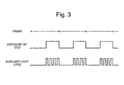
- the drive circuit 15 supplies a drive current of a predetermined duty ratio (equal to or smaller than 100%) to the first to third LEDs 16 to 18 in response to an image start timing signal supplied from the MPU 7. Then, the drive circuit 15 stops supplying the drive current to the first to third LEDs 16 to 18 in response to an image end timing signal supplied from the MPU 7. In this manner, the drive circuit 15 duty-drives the first to third LEDs 16 to 18 in synchronization with a period (imaging period) during which the CCD 3 is actually imaging the photo-object, in other words a period (exposure period) during which the CCD3 is exposed, of a frame period.
- a predetermined duty ratio equal to or smaller than 100%
- the drive circuit 15 supplies the first to third LEDs 16 to 18 with a drive current having a level which is preset correspondingly to the level (voltage value) of a light intensity control signal (direct current voltage signal) supplied from the D/A converter 14 and the duty ratio for driving the first to third LEDs 16 to 18. Due to this, the drive circuit 15 can irradiate an auxiliary light in a desired light intensity onto the photo-object.
- the first to third LEDs 16 to 18 emit a white emission light.
- the first to third LEDs 16 to 18 emit a light intermittently, thereby irradiate an auxiliary light onto the photo-object.
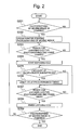
- FIG. 2 is a main flowchart showing an operation of taking a moving picture performed by the electronic still camera 1, which is the imaging apparatus of the present invention. Each process shown in this flowchart is performed by a program stored in the MROM 13 or the like being read by the MPU 7 which is the main control circuit.
- the electronic still camera 1 waits for an instruction for starting taking a moving picture to be given by a user via a shutter key or the like (step S201). Until such an instruction for starting taking a moving picture is given, the electronic still camera 1 is looping in step S201.
- the electronic still camera 1 performs various initialization processes such as securing of storage area for taken picture data, and initialization of an AF (Automatic Focus) lens position, etc., and start taking a moving picture (step S202).
- the electronic still camera 1 While a moving picture is taken, the electronic still camera 1 repeatedly performs processes of steps S203 to 5209.
- the MPU 7 determines whether it is the timing for exposing the CCD 3 in order to take a picture corresponding to one frame of the moving picture (step S203), and waits until the timing for exposing the CCD 3 comes by looping in step S203 (step S203: No).
- the timing for starting exposing the CCD 3 comes (step S203: Yes)
- the MPU 7 starts exposing the CCD 3 (step S204) and performs the following steps while performing exposure.
- the MPU 7 determines in step S205 whether exposure of the photo-object is insufficient or not. In a case where determining that exposure of the photo-object is insufficient, that is, the photo-object lacks in light amount and is dark (step S205: Yes), the MPU 7 drives the LEDs at predetermined timings shown in the timing charts (see FIG. 3 , FIGS. 5 to 7 ) to be explained in the respective embodiments of the present invention (step S206). On the contrary, in a case where determining that exposure of the photo-object is sufficient (step S205: No), the MPU 7 skips the process of step S206.
- the MPU 7 may perform determination on the brightness of the photo-object before step S204 and set a flag such as an LED drive flag or the like in a case where exposure of the photo-object is insufficient. Then in step S205, the MPU 7 may determine whether to drive the LEDs, based on the LED drive flag. Further, the MPU 7 may employ a method where it performs determination on whether to drive the LEDs only once for each taking of a moving picture. In this case, the MPU 7 may perform determination on whether the exposure of the photo-object is insufficient before, for example, step S202, and store the determination result by a flag.
- the MPU 7 repeats the processes of step S205 and step S206 until the timing at which the exposing period for taking one frame of a moving picture ends. Specifically, the MPU 7 determines in step S207 whether the timing at which the CCD exposing period for taking one frame of a moving picture ends comes or not, and returns to step S205 to perform the loop process unless the exposing period ends (step S207: No).
- step S207: Yes the MPU 7 finishes exposure of the CCD 3(step S208), and applies image processing, compression processing, etc. to the obtained images and store them.
- image processing and storing processing is omitted herein, because they are publicly well-known techniques.
- step S209: No taking of the moving picture is finished
- step S209: No taking of the moving picture is finished
- step S209: Yes an instruction for finishing taking a moving picture is given by the user by, for example, pushing a shutter key
- an image start timing signal is supplied to the drive circuit 15 from the MPU 7.
- the drive circuit 15 supplies a drive current having a level corresponding to the level of a light intensity control signal and the duty ratio to the first to third LEDs 16 to 18, thereby duty-driving the first to third LEDs 16 to 18.
- an image end timing signal is supplied to the drive circuit 15 from the MPU 7.
- the drive circuit 15 stops supplying the drive current to the first to third LEDs 16 to 18 to stop driving of the first to third LEDs 16 to 18.
- the drive circuit 15 can drive the first to third LEDs 16 to 18 to emit a light intermittently in synchronization with an imaging period (exposure period) of a frame period.
- the drive circuit 15 does not drive the first to third LEDs 16 to 18 in a period during which the CCD 3 does not perform imaging, i.e. a period during which no auxiliary light is needed to be irradiated onto the photo-object, as explained above. Therefore, the electronic still camera 1 can reduce the amount of electricity to be consumed.
- the drive circuit 15 duty-drives the first to third LEDs 16 to 18 to emit a light intermittently during the imaging period (exposure period)
- the electronic still camera 1 achieves a higher heat releasing effect than in a case where the first to third LEDs 16 to 18 emit a light all the time during the imaging period (exposure period), and thereby can reduce the amount of heat generated in the first to third LEDs 16 to 18.
- the electronic still camera 1 can increase the amount of light emitted by the first to third LEDs 16 to 18 and can reduce the amount of electricity to be consumed by the first to third LEDs 16 to 18, particularly reduce the amount of electricity to be consumed when the first to third LEDs 16 to 18 irradiate an auxiliary light onto the photo-object As a result, the electronic still camera 1 can have a longer use time per battery, or a longer use time per charging.
- the drive circuit 15 duty-drives the first to third LEDs 16 to 18 only during the imaging period (exposure period) of the CCD 3.
- the present invention is not limited to this, but the drive circuit 15 may duty-drive the first to third LEDs 16 to 18 throughout the period during which taking of a moving picture is performed. Even in this case, the light emitting efficiency of the first to third LEDs 16 to 18 is improved. Therefore, the electronic still camera 1 can reduce the amount of electricity to be consumed by the first to third LEDs 16 to 18.
- the MPU 7 since the MPU 7 needs to supply only a photographing timing signal representing the timing to start photographing and photographing timing signal representing the timing to end the photographing to the drive circuit 15, the processing load of the MPU 7 can be reduced and the operation to be performed by the drive circuit 15 can be simplified. Furthermore, if the first to third LEDs 16 to 18 are duty-driven throughout the period, a user can be free from perceiving flickering of the auxiliary light on the photo-object due to cyclic light emission.
- the electronic still camera 1 comprises three LEDs.
- the present invention is not limited to this, but the number of LEDs comprised in the electronic still camera 1 may be arbitrary, for example, one or equal to or more than four.
- the color of the light emitted by the first to third LEDs 16 to 18 is white.
- the present invention is not limited to this, but the first to third LEDs 16 to 18 may emit lights having different colors.
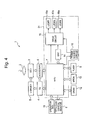
- the first to third LEDs 16 to 18 may be replaced with three LEDs (for example, LEDs 16a, 17a, and 18a shown in FIG. 4 ) having different light emission colors (for example, R, G, and B shown in FIG. 4 )
- the color of the light may be changed frame by frame.
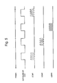
- a second exemplary embodiment will now be explained with reference to timing charts shown in FIG. 5 .
- the drive circuit 15 duty-drives only one of the first to third LEDs 16 to 18 during a photographing period as shown in FIG. 5 , and sequentially switches the LEDs to be driven frame by frame, for example, in the order of the first LED 16, the second LED 17, and the third LED 18.
- the drive circuit 15 sequentially switches the LEDs to be driven in response to an image start timing signal and an image end timing signal supplied from the MPU 7.
- the drive circuit 15 drives each of the first to third LEDs 16 to 18 once in three frame periods as explained above, it is possible to heighten the heat releasing effect of the first to third LEDs 16 to 18, as compared to the first embodiment where the first to third LEDs 16 to 18 are driven once in one frame period.
- the electronic still camera 1 of the present embodiment can further improve the light emitting efficiency of the first to third LEDs 16 to 18 and can further reduce the amount of electricity to be consumed, as compared to the first embodiment.
- the drive circuit 15 is connected to three LEDs (first to third LEDs 16 to 18).
- the present invention is not limited to this, but the number of LEDs connected to the drive circuit 15 may be arbitrary. As the number of LEDs connected to the drive circuit 15 increases, the time interval for driving each LED is elongated. Therefore, the heat releasing effect of each LED can be heightened accordingly.
- the drive circuit 15 sequentially switches the first to third LEDs 16 to 18 frame by frame and duty-drives one of them during the imaging period (exposure period).
- the present invention is not limited to this, but the drive circuit 15 may drive a plurality of LEDs in one frame period and switch the LEDs sequentially frame by frame.
- the electronic still camera 1 can increase the amount of auxiliary light to be emitted as compared to the above-described embodiment, by making groups each including a plurality of LEDs and driving each group of LEDs by sequentially switching the groups frame by frame as described above.
- the colors of the lights emitted by the first to third LEDs 16 to 18 may be different.
- the color of the light emitted by the first LED 16 may be red
- the color of the light emitted by the second LED 17 may be green
- the color of the light emitted by the third LED 18 may be blue.
- the color of the light to be emitted may be changed frame by frame.
- the drive circuit 15 drives the first to third LEDs 16 to 18 by switching the first to third LEDs 16 to 18 sequentially within one imaging period (exposure period), as shown in FIG. 6 .
- the MPU 7 supplies a switch timing signal to the drive circuit 15 twice in one imaging period (exposure period), and the drive circuit 15 sequentially switches the LEDs to be driven in response to this switch timing signal.
- the drive circuit 15 can achieve the same effect as the case of duty-driving. That is, the electronic still camera 1 can reduce the amount of heat generated in the first to third LEDs I6 to 18, and can improve the light emitting efficiency of the first to third LEDs 16 to 18.
- the duty ratio can be reduced by driving the first to third LEDs 16 to 18 in the manner described above.
- the heat releasing effect of the first to third LEDs 16 to 18 is heightened and thus the light emitting efficiency thereof is improved. Accordingly, the electronic still camera 1 can increase the amount of light emission and can reduce the amount of electricity to be consumed.
- the present invention is not limited to the above-described embodiment, but can be modified and applied in various ways. Modifications of the above-described embodiment which can be applied to the present invention will be explained below.
- the drive circuit 15 drives each of the first to third LEDs 16 to 18 once in one imaging period (exposure period).
- the present invention is not limited to this, but the drive circuit 15 may drive each of the first to third LEDs 16 to 18 more than once in one imaging period (exposure period) by cyclically switching the first to third LEDs 16 to 18. In this manner, the drive circuit 15 can further reduce the duty ratio of the first to third LEDs 16 to 18, as compared to the above-described embodiment.
- the drive circuit 15 may drive a plurality of LEDs in one frame period, and may sequentially switch the LEDs to be driven frame by frame. Due to this, the electronic still camera 1 can increase the amount of auxiliary light to be generated, as compared to the above-described embodiment.
- the colors of the lights emitted by the first to third LEDs 16 to 18 may be different.
- the color of the light emitted by the first LED 16 may be red
- the color of the light emitted by the second LED 17 may be green
- the color of the light emitted by the third LED 18 may be blue.
- the color of the light to be emitted may be changed frame by frame.
- a fourth exemplary embodiment will now be explained with reference to timing charts shown in FIG. 7 .
- the drive circuit 15 drives the first to third LEDs 16 to 18 in one imaging period (exposure period) by partially synchronizing the periods for driving the respective LEDs, as shown in FIG. 7 .
- the MPU 7 supplies a drive start timing signal and a drive end timing signal to the drive circuit 15 in a predetermined cycle.
- the drive circuit 15 can reduce the amount of electricity consumed by the first to third LEDs 16 to 18, likewise the third embodiment.
- the present invention is not limited to an electronic still camera, but can be applied to any imaging apparatus if it has a function for taking a moving picture.
- the present invention can be applied to a cellular phone with a camera, a PDA (Personal Digital Assistant) with a camera.
- the present invention can achieve a more remarkable effect if applied to a cellular phone with a camera, because a cellular phone with a camera has a smaller power source capacity than that of an electronic still camera.
- the first to fourth embodiments have been explained by employing a case where the function of drive means is realized by the drive circuit 15 as an example.
- the present invention is not limited to this example.
- Part of the function of the drive means of the present invention may be realized by the MPU 7, or part of the function of the drive means of the present invention may be realized by the MPU 7 by reading and executing a program stored in the MROM 13.
- the present invention is not limited to this type of illumination apparatus, but can be applied to an illumination apparatus which is separate from an electronic still camera.
Landscapes
- Engineering & Computer Science (AREA)
- Multimedia (AREA)
- Signal Processing (AREA)
- Physics & Mathematics (AREA)
- General Physics & Mathematics (AREA)
- Studio Devices (AREA)
- Stroboscope Apparatuses (AREA)
- Image Input (AREA)
Claims (3)
- Appareil imageur (1) comportant un dispositif de lecteur d'image (3) pour imager un photo-objet et comportant également une fonction pour imager une image mobile constituée par une pluralité de trames, ledit appareil imageur (1) comprenant :une pluralité de diodes émettrices de lumière (16, 17, 18) jouant le rôle de source de lumière d'une lumière auxiliaire destinée à être irradiée sur un photo-objet ; etun moyen de pilotage (15) pour piloter ladite pluralité de diodes émettrices de lumière (16, 17, 18),caractérisé en ce que :le moyen de pilotage (15) est adapté pour piloter ladite pluralité de diodes émettrices de lumière (16, 17, 18) en réalisant une commutation séquentielle entre différents jeux d'une ou de plusieurs desdites diodes émettrices de lumière (16, 17, 18) et en répétant la commutation séquentielle une pluralité de fois pendant une même période de formation d'image d'une période de trame.
- Appareil imageur (1) selon la revendication 1, dans lequel ledit moyen de pilotage (15) commande le pilotage de ladite pluralité de diodes émettrices de lumière (16, 17, 18) selon une unité constituée par un groupe de diodes émettrices de lumière (16) incluant certaines de ladite pluralité de diodes émettrices de lumière (16, 17, 18) et pilote ladite pluralité de diodes émettrices de lumière (16, 17, 18) en réalisant une commutation séquentielle de groupes de diodes émettrices de lumière destinées à être pilotées pendant la période de formation d'image de la période de trame.
- Procédé d'obtention d'une image mobile constituée par une pluralité de trames en lisant des images au moyen d'un dispositif de lecteur (3) pour imager un photo-objet, comprenant :une étape de pilotage pour piloter une pluralité de diodes émettrices de lumière (16, 17, 18) jouant le rôle de source de lumière d'une lumière auxiliaire destinée à être irradiée sur un photo-objet,caractérisé par :le pilotage de ladite pluralité de diodes émettrices de lumière (16, 17, 18) en réalisant une commutation séquentielle entre différents jeux d'une ou de plusieurs desdites diodes émettrices de lumière (16, 17, 18) et en répétant la commutation séquentielle une pluralité de fois pendant une même période de formation d'image d'une période de trame.
Applications Claiming Priority (3)
| Application Number | Priority Date | Filing Date | Title |
|---|---|---|---|
| JP2002381364 | 2002-12-27 | ||
| JP2002381364A JP2005150774A (ja) | 2002-12-27 | 2002-12-27 | 照明装置及び撮像装置 |
| PCT/JP2003/016883 WO2004062268A1 (fr) | 2002-12-27 | 2003-12-26 | Appareil d'eclairage et procede d'eclairage pour appareil d'imagerie |
Publications (2)
| Publication Number | Publication Date |
|---|---|
| EP1576805A1 EP1576805A1 (fr) | 2005-09-21 |
| EP1576805B1 true EP1576805B1 (fr) | 2008-05-28 |
Family
ID=32708487
Family Applications (1)
| Application Number | Title | Priority Date | Filing Date |
|---|---|---|---|
| EP03768310A Expired - Lifetime EP1576805B1 (fr) | 2002-12-27 | 2003-12-26 | Appareil d'eclairage et procede d'eclairage pour appareil d'imagerie |
Country Status (9)
| Country | Link |
|---|---|
| US (1) | US7746405B2 (fr) |
| EP (1) | EP1576805B1 (fr) |
| JP (1) | JP2005150774A (fr) |
| KR (1) | KR100752812B1 (fr) |
| CN (1) | CN1729682A (fr) |
| AU (1) | AU2003291766A1 (fr) |
| DE (1) | DE60321385D1 (fr) |
| TW (1) | TWI239768B (fr) |
| WO (1) | WO2004062268A1 (fr) |
Families Citing this family (32)
| Publication number | Priority date | Publication date | Assignee | Title |
|---|---|---|---|---|
| JP4576107B2 (ja) * | 2003-10-27 | 2010-11-04 | Hoya株式会社 | 照明制御装置 |
| KR100621007B1 (ko) * | 2004-02-19 | 2006-09-08 | 엘지전자 주식회사 | 휴대단말기의 카메라 플래쉬 장치 및 제어방법 |
| JP4772357B2 (ja) | 2005-03-31 | 2011-09-14 | オリンパスメディカルシステムズ株式会社 | 光源装置及び撮像装置 |
| US9107568B2 (en) * | 2005-06-17 | 2015-08-18 | Intellectual Ventures Ii Llc | Capsule type endoscope and method for fabricating the same |
| KR100885803B1 (ko) | 2005-06-17 | 2009-02-26 | 매그나칩 반도체 유한회사 | 이미지센서 및 그의 조명원제어방법 |
| JP2007052154A (ja) * | 2005-08-17 | 2007-03-01 | Matsushita Electric Ind Co Ltd | ストロボ装置及びストロボ付き撮像装置並びにストロボ装置の発光制御方法 |
| US7400826B2 (en) * | 2005-08-29 | 2008-07-15 | Avago Technologies Ecbu Ip Pte Ltd | Imaging device and method for producing a flash of light with pulsing |
| GB2433370A (en) * | 2005-12-16 | 2007-06-20 | Gekko Technology Ltd | Synchronising artificial light sources with camera image capture |
| JP2007171364A (ja) | 2005-12-20 | 2007-07-05 | Samsung Electronics Co Ltd | 可視光led光源装置、それを用いた画像投影システムおよび可視光ledの駆動方法 |
| US20070138979A1 (en) * | 2005-12-20 | 2007-06-21 | Samsung Electronics Co., Ltd. | LED illumination unit, projection display device using the same, and method of operating LED illumination unit |
| US7898593B2 (en) * | 2006-02-16 | 2011-03-01 | Photon Technology International, Inc. | System and method for synchronizing an illuminator to a video camera |
| JP4899534B2 (ja) * | 2006-02-28 | 2012-03-21 | ソニー株式会社 | 監視カメラ |
| US7439679B2 (en) * | 2006-03-16 | 2008-10-21 | Motorola, Inc. | Method and apparatus for illuminating light sources within an electronic device |
| KR100809286B1 (ko) * | 2006-12-09 | 2008-03-07 | 이구 | 감시카메라 영상 신호 처리장치 |
| US20100013934A1 (en) * | 2006-12-27 | 2010-01-21 | Datalogic Automation S.R.L. | System for image acquisition |
| KR101441383B1 (ko) * | 2007-12-03 | 2014-09-18 | 엘지디스플레이 주식회사 | 액정표시장치 및 이의 구동방법 |
| JP2009139553A (ja) * | 2007-12-05 | 2009-06-25 | Samsung Techwin Co Ltd | 撮像装置および撮像方法 |
| KR100917012B1 (ko) * | 2008-02-27 | 2009-09-10 | 주식회사 아이닉스 | 영상 획득 장치 및 방법 |
| JP5327436B2 (ja) * | 2008-09-22 | 2013-10-30 | 東芝ライテック株式会社 | テレビカメラの撮影装置 |
| KR101009366B1 (ko) * | 2009-07-17 | 2011-01-19 | 주식회사 씨앤비텍 | 동화상 카메라 |
| TW201138443A (en) * | 2010-04-27 | 2011-11-01 | Anmo Electronics Corp | Digital imaging apparatus and related object inspection system |
| WO2013121616A1 (fr) * | 2012-02-17 | 2013-08-22 | オリンパスメディカルシステムズ株式会社 | Dispositif endoscopique |
| CN103135320B (zh) * | 2013-03-04 | 2015-08-19 | 南京农业大学 | 用于采集农业物料高质量图像的led灯箱 |
| CN104660914B (zh) * | 2013-11-18 | 2019-01-08 | 杭州海康威视数字技术股份有限公司 | 一种高清相机的实现方法以及一种高清相机 |
| WO2016018372A1 (fr) * | 2014-07-31 | 2016-02-04 | Hewlett-Packard Development Company, L.P. | Génération de flash blanc à partir d'un projecteur à diodes électroluminescentes (led) |
| DE102015105656B4 (de) * | 2015-04-14 | 2025-02-13 | Chromasens Gmbh | Steuermodul für eine Kamera, Kamera, Produktionssystem und Verfahren zum Erfassen von Bildern mittels einer solchen Kamera |
| CN107004132B (zh) * | 2015-10-09 | 2021-01-05 | 华为技术有限公司 | 眼球跟踪装置及其辅助光源控制方法及相关装置 |
| US11043119B2 (en) * | 2017-03-30 | 2021-06-22 | Nec Corporation | Imaging system, imaging method, and imaging control program |
| JP6931191B2 (ja) * | 2017-09-20 | 2021-09-01 | 東芝ライテック株式会社 | 調光制御装置、照明器具および照明システム |
| KR101851527B1 (ko) * | 2017-12-22 | 2018-06-11 | (주)비엠웍스 | 다중 동기신호를 이용한 저 전력 감시 시스템 |
| TWI845170B (zh) * | 2023-02-18 | 2024-06-11 | 廣達電腦股份有限公司 | 亮度控制裝置以及亮度控制方法 |
| WO2025120787A1 (fr) * | 2023-12-07 | 2025-06-12 | 三菱電機株式会社 | Dispositif de commande de source de lumière et système de source de lumière |
Family Cites Families (17)
| Publication number | Priority date | Publication date | Assignee | Title |
|---|---|---|---|---|
| US5010412A (en) * | 1988-12-27 | 1991-04-23 | The Boeing Company | High frequency, low power light source for video camera |
| DE4011842A1 (de) * | 1990-04-12 | 1991-10-17 | Fraunhofer Ges Forschung | Beleuchtungseinrichtung |
| JPH05219447A (ja) | 1991-02-26 | 1993-08-27 | Nippon Signal Co Ltd:The | Tvカメラ用照明装置 |
| JP2994139B2 (ja) * | 1992-05-21 | 1999-12-27 | 小糸工業株式会社 | テレビカメラ用led照明装置 |
| JP3535660B2 (ja) * | 1996-06-28 | 2004-06-07 | キヤノン株式会社 | 画像読取り装置および画像読取り方法 |
| JP3172496B2 (ja) | 1998-09-29 | 2001-06-04 | 三洋電機株式会社 | 編集装置およびそれを具備したデジタルカメラ |
| KR100338596B1 (ko) * | 1998-10-16 | 2002-05-27 | 미다라이 후지오 | 광학소자, 광학소자의 유지구조 및 촬상장치 |
| US6495964B1 (en) * | 1998-12-18 | 2002-12-17 | Koninklijke Philips Electronics N.V. | LED luminaire with electrically adjusted color balance using photodetector |
| KR20000059712A (ko) * | 1999-03-08 | 2000-10-05 | 김영환 | 고체촬상소자의 영상신호 처리 장치 |
| US6822687B1 (en) * | 1999-07-08 | 2004-11-23 | Pentax Corporation | Three-dimensional image capturing device and its laser emitting device |
| JP2001215579A (ja) | 2000-01-31 | 2001-08-10 | Casio Comput Co Ltd | 撮像装置及びそのストロボ制御方法 |
| JP4288553B2 (ja) | 2000-07-25 | 2009-07-01 | 富士フイルム株式会社 | カメラのストロボ装置 |
| JP3907397B2 (ja) | 2000-10-11 | 2007-04-18 | 富士通株式会社 | 映像監視装置 |
| US20020191102A1 (en) * | 2001-05-31 | 2002-12-19 | Casio Computer Co., Ltd. | Light emitting device, camera with light emitting device, and image pickup method |
| JP2003084344A (ja) * | 2001-09-14 | 2003-03-19 | Casio Comput Co Ltd | 閃光装置及びそれを備えたカメラ装置、閃光装置の色温度制御方法 |
| JP2005128413A (ja) * | 2003-10-27 | 2005-05-19 | Pentax Corp | 照明制御装置 |
| US7400826B2 (en) * | 2005-08-29 | 2008-07-15 | Avago Technologies Ecbu Ip Pte Ltd | Imaging device and method for producing a flash of light with pulsing |
-
2002
- 2002-12-27 JP JP2002381364A patent/JP2005150774A/ja not_active Abandoned
-
2003
- 2003-12-26 KR KR1020057009785A patent/KR100752812B1/ko not_active Expired - Fee Related
- 2003-12-26 WO PCT/JP2003/016883 patent/WO2004062268A1/fr not_active Ceased
- 2003-12-26 AU AU2003291766A patent/AU2003291766A1/en not_active Abandoned
- 2003-12-26 CN CNA2003801069911A patent/CN1729682A/zh active Pending
- 2003-12-26 TW TW092136966A patent/TWI239768B/zh not_active IP Right Cessation
- 2003-12-26 EP EP03768310A patent/EP1576805B1/fr not_active Expired - Lifetime
- 2003-12-26 DE DE60321385T patent/DE60321385D1/de not_active Expired - Lifetime
-
2005
- 2005-06-27 US US11/167,546 patent/US7746405B2/en not_active Expired - Fee Related
Also Published As
| Publication number | Publication date |
|---|---|
| KR100752812B1 (ko) | 2007-08-29 |
| US20050231633A1 (en) | 2005-10-20 |
| US7746405B2 (en) | 2010-06-29 |
| TWI239768B (en) | 2005-09-11 |
| KR20050085226A (ko) | 2005-08-29 |
| JP2005150774A (ja) | 2005-06-09 |
| DE60321385D1 (de) | 2008-07-10 |
| TW200423717A (en) | 2004-11-01 |
| EP1576805A1 (fr) | 2005-09-21 |
| CN1729682A (zh) | 2006-02-01 |
| AU2003291766A1 (en) | 2004-07-29 |
| WO2004062268A1 (fr) | 2004-07-22 |
Similar Documents
| Publication | Publication Date | Title |
|---|---|---|
| EP1576805B1 (fr) | Appareil d'eclairage et procede d'eclairage pour appareil d'imagerie | |
| US7209652B2 (en) | Lighting control apparatus with a plurality of lighting devices | |
| TWI223123B (en) | Flash device, camera apparatus having the flash device, method of causing the flash device to emit colored rays of light therefrom, and recording medium in which program to control the flash device so as to emit desired colored rays of light is stored | |
| US7949247B2 (en) | Imaging apparatus including strobe light emitting function | |
| JP4168617B2 (ja) | 撮像装置用閃光装置、閃光装置付撮像装置及び撮像方法 | |
| JP2001215579A (ja) | 撮像装置及びそのストロボ制御方法 | |
| KR20100079831A (ko) | 디지털 카메라 및 그 제어방법 | |
| JP2005354155A (ja) | 動画撮像装置 | |
| US7660520B2 (en) | Camera system with current and discharge controlled illumination | |
| JP2009500937A (ja) | 走査型フラッシュ装置を備えるデジタル画像取り込み装置 | |
| US20090148148A1 (en) | Photographing apparatus and photographing method | |
| JP4971190B2 (ja) | Ledフラッシュ制御 | |
| US7505077B2 (en) | Lighting control apparatus | |
| JP2003084341A (ja) | 閃光装置付撮像装置、撮像装置の発光部の発光方法及びプログラム | |
| KR101124243B1 (ko) | 휴대기기용 디지털 카메라 | |
| JP2002357859A (ja) | 閃光装置及びそれを用いた電子スチルカメラ | |
| JP2004242123A (ja) | 撮像装置 | |
| JP2008058978A (ja) | 閃光機能付撮像装置及び撮像装置の発光制御方法 | |
| JP2007047544A (ja) | ストロボ装置 | |
| JP5047465B2 (ja) | 携帯機器用デジタルカメラ | |
| JP2006201766A (ja) | 撮像装置及びそのストロボ制御方法 | |
| JP2003084345A (ja) | 閃光装置及びそれを備えたカメラ装置、閃光装置の発光素子駆動方法 | |
| JP2025128695A (ja) | 照明装置及び撮像システムとその制御方法 | |
| JP2006145877A (ja) | カメラ | |
| JP2004184662A (ja) | ストロボ装置 |
Legal Events
| Date | Code | Title | Description |
|---|---|---|---|
| PUAI | Public reference made under article 153(3) epc to a published international application that has entered the european phase |
Free format text: ORIGINAL CODE: 0009012 |
|
| 17P | Request for examination filed |
Effective date: 20050606 |
|
| AK | Designated contracting states |
Kind code of ref document: A1 Designated state(s): AT BE BG CH CY CZ DE DK EE ES FI FR GB GR HU IE IT LI LU MC NL PT RO SE SI SK TR |
|
| AX | Request for extension of the european patent |
Extension state: AL LT LV MK |
|
| DAX | Request for extension of the european patent (deleted) | ||
| RBV | Designated contracting states (corrected) |
Designated state(s): DE FR GB |
|
| 17Q | First examination report despatched |
Effective date: 20051012 |
|
| GRAP | Despatch of communication of intention to grant a patent |
Free format text: ORIGINAL CODE: EPIDOSNIGR1 |
|
| GRAS | Grant fee paid |
Free format text: ORIGINAL CODE: EPIDOSNIGR3 |
|
| GRAA | (expected) grant |
Free format text: ORIGINAL CODE: 0009210 |
|
| AK | Designated contracting states |
Kind code of ref document: B1 Designated state(s): DE FR GB |
|
| REG | Reference to a national code |
Ref country code: GB Ref legal event code: FG4D |
|
| REF | Corresponds to: |
Ref document number: 60321385 Country of ref document: DE Date of ref document: 20080710 Kind code of ref document: P |
|
| PLBE | No opposition filed within time limit |
Free format text: ORIGINAL CODE: 0009261 |
|
| STAA | Information on the status of an ep patent application or granted ep patent |
Free format text: STATUS: NO OPPOSITION FILED WITHIN TIME LIMIT |
|
| 26N | No opposition filed |
Effective date: 20090303 |
|
| REG | Reference to a national code |
Ref country code: FR Ref legal event code: PLFP Year of fee payment: 13 |
|
| REG | Reference to a national code |
Ref country code: FR Ref legal event code: PLFP Year of fee payment: 14 |
|
| REG | Reference to a national code |
Ref country code: FR Ref legal event code: PLFP Year of fee payment: 15 |
|
| PGFP | Annual fee paid to national office [announced via postgrant information from national office to epo] |
Ref country code: FR Payment date: 20171113 Year of fee payment: 15 |
|
| PGFP | Annual fee paid to national office [announced via postgrant information from national office to epo] |
Ref country code: GB Payment date: 20171220 Year of fee payment: 15 |
|
| PGFP | Annual fee paid to national office [announced via postgrant information from national office to epo] |
Ref country code: DE Payment date: 20171220 Year of fee payment: 15 |
|
| REG | Reference to a national code |
Ref country code: DE Ref legal event code: R119 Ref document number: 60321385 Country of ref document: DE |
|
| GBPC | Gb: european patent ceased through non-payment of renewal fee |
Effective date: 20181226 |
|
| PG25 | Lapsed in a contracting state [announced via postgrant information from national office to epo] |
Ref country code: FR Free format text: LAPSE BECAUSE OF NON-PAYMENT OF DUE FEES Effective date: 20181231 Ref country code: DE Free format text: LAPSE BECAUSE OF NON-PAYMENT OF DUE FEES Effective date: 20190702 |
|
| PG25 | Lapsed in a contracting state [announced via postgrant information from national office to epo] |
Ref country code: GB Free format text: LAPSE BECAUSE OF NON-PAYMENT OF DUE FEES Effective date: 20181226 |