EP1576869B1 - Dispositif de mesure pour mesurer l'humidité superficielle - Google Patents
Dispositif de mesure pour mesurer l'humidité superficielle Download PDFInfo
- Publication number
- EP1576869B1 EP1576869B1 EP05003748A EP05003748A EP1576869B1 EP 1576869 B1 EP1576869 B1 EP 1576869B1 EP 05003748 A EP05003748 A EP 05003748A EP 05003748 A EP05003748 A EP 05003748A EP 1576869 B1 EP1576869 B1 EP 1576869B1
- Authority
- EP
- European Patent Office
- Prior art keywords
- dew point
- working machine
- agricultural working
- measuring device
- control unit
- Prior art date
- Legal status (The legal status is an assumption and is not a legal conclusion. Google has not performed a legal analysis and makes no representation as to the accuracy of the status listed.)
- Expired - Lifetime
Links
- 239000000463 material Substances 0.000 claims abstract description 12
- 238000005520 cutting process Methods 0.000 claims description 31
- 238000004140 cleaning Methods 0.000 claims description 22
- 238000011156 evaluation Methods 0.000 claims description 9
- XLYOFNOQVPJJNP-UHFFFAOYSA-N water Substances O XLYOFNOQVPJJNP-UHFFFAOYSA-N 0.000 claims description 8
- 230000010355 oscillation Effects 0.000 claims description 4
- 230000001105 regulatory effect Effects 0.000 claims description 4
- 230000001419 dependent effect Effects 0.000 claims description 2
- 238000003306 harvesting Methods 0.000 abstract description 5
- 235000013339 cereals Nutrition 0.000 description 21
- 239000010902 straw Substances 0.000 description 12
- 239000000203 mixture Substances 0.000 description 6
- 230000004044 response Effects 0.000 description 6
- 210000000056 organ Anatomy 0.000 description 5
- 230000000694 effects Effects 0.000 description 4
- 230000006870 function Effects 0.000 description 4
- 239000004464 cereal grain Substances 0.000 description 3
- 230000008859 change Effects 0.000 description 3
- 238000002360 preparation method Methods 0.000 description 3
- 230000007423 decrease Effects 0.000 description 2
- 238000000034 method Methods 0.000 description 2
- 230000008569 process Effects 0.000 description 2
- 238000003860 storage Methods 0.000 description 2
- 230000009471 action Effects 0.000 description 1
- 230000033228 biological regulation Effects 0.000 description 1
- 238000009833 condensation Methods 0.000 description 1
- 230000005494 condensation Effects 0.000 description 1
- 239000000470 constituent Substances 0.000 description 1
- 238000001816 cooling Methods 0.000 description 1
- 238000001514 detection method Methods 0.000 description 1
- 238000009826 distribution Methods 0.000 description 1
- 239000004570 mortar (masonry) Substances 0.000 description 1
- 239000002245 particle Substances 0.000 description 1
- 238000000926 separation method Methods 0.000 description 1
- 230000032258 transport Effects 0.000 description 1
Images
Classifications
-
- A—HUMAN NECESSITIES
- A01—AGRICULTURE; FORESTRY; ANIMAL HUSBANDRY; HUNTING; TRAPPING; FISHING
- A01D—HARVESTING; MOWING
- A01D41/00—Combines, i.e. harvesters or mowers combined with threshing devices
- A01D41/12—Details of combines
- A01D41/127—Control or measuring arrangements specially adapted for combines
Definitions
- the invention relates to an agricultural working machine with a measuring device according to the preamble of claim 1.
- a device for determining the mass of a good in which the mass of harvested cereal grains is calculated by a mass computer from the volume and density of the crop.
- the volume is measured for this purpose via a level sensor, which detects the contents of the Erntegut matterers.
- the density is stored in a density calculator, the density relevant for determining the mass being stored as a function of the moisture content.
- the moisture of the harvested cereal grains is either manually entered or determined by sensors in this device.
- the known measuring devices have the disadvantage that they sense the moisture of the harvested cereal grains and not the surface moisture on the crop.
- the surface moisture of the crop is used in the setting of the crop Operating parameters of the working bodies and / or the receiving attachment so far not taken into account.
- At least one dew point sensor for sensing the air surrounding the crop on the work machine, a proportion of water condensed from the water vapor portion of the air can be sensed.
- the dew point sensor generated by the dew point sensor can be regarded as representative of existing on the crop and / or the working surface moisture.
- the dew point sensor So that the surface moisture condensed on the crop can be detected, the dew point sensor generates a dew point signal dependent on the condensed water vapor content of the air.
- a particularly advantageous embodiment results when the dew point sensor is connected to an evaluation and display unit which calculates and displays a dew point temperature from the dew point signal so that the operator can monitor the measured variable measured by the dew point sensor.
- a particularly economical embodiment is possible if an operator changes the setting of at least one operating parameter of at least one working element and / or at least one receiving attachment and / or the traveling speed of the agricultural machine due to the dewpoint temperature displayed on the evaluation and display unit.
- the dew point sensor with a control unit connected, which changes one or more operating parameters of at least one working organ and / or at least one receiving attachment of the agricultural machine in response to the transferred from the dew point sensor to the control unit dew point signal.
- the control unit advantageously contains at least one characteristic with which at least one operating parameter is regulated.
- the optimum operating parameters are thus tuned without the driver's intervention, whereby the driver is relieved.
- the agricultural machine is a self-propelled combine harvester with a designed as a cutting attachment header, with several dew point sensors are arranged at different heights on the cutting unit, the air can be sensed at different heights in the crop to be harvested.
- a particularly advantageous embodiment results when the cutting unit is connected to the control unit and the control unit regulates a cutting height of the cutting unit as a function of the dew point signal, so that the surface moisture of the crop to be harvested is taken into account when setting the cutting unit.
- the combine harvester is equipped at least with at least one rudder bar which is connected to the control unit, wherein the control unit controls the travel speed of the combine harvester in response to the dew point signal so that the travel speed can be adapted to the surface moisture of the crop.
- the combine harvester is equipped at least with a threshing unit with a threshing drum and at least one concave and the threshing unit is connected to the control unit, the control unit having at least one threshing drum speed of the at least one threshing drum and / or one threshing gap between the at least one threshing basket and the threshing drum in response to the dew point signal to adjust the optimum operating parameters of the threshing unit for the determined surface moisture of the crop to be harvested.
- the combine harvester is equipped with at least one cleaning device with at least one screen and at least one fan and the cleaning device is connected to the control unit, wherein the control unit at least one mesh of the at least one screen and / or a fan speed of the at least one fan and / / or regulates an oscillation frequency of the cleaning device as a function of the dew point signal, the surface moisture of the crop to be harvested can be included in the choice of operating parameters.
- At least one further dew point sensor is arranged in the region of the sieves of the cleaning device.
- a further dew point sensor is arranged in the region of a separating device of the combine harvester, so that the surface moisture of the product stream conveyed on the tray shakers and consisting of threshed stalks is detected.
- another dew point sensor is arranged on the feed shaft of the combine harvester.
- a further dew point sensor is arranged in the region of the threshing unit, so that the surface moisture of the grain-chaff mixture separated on the threshing basket can be detected.
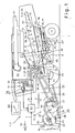
- Fig. 1 is an executed as a self-propelled harvester 1 agricultural machine 2 shown in the side view during harvesting.
- a combine harvester 1 with a so-called. Tangentialdrehisk 3 and a behind arranged Horden yetler 4 as a separator 5.
- Horden—lers 4 Below the Horden yetlers 4 is located There is a cleaning device 6, consisting of two superimposed usually driven in a swinging sieves 7, 8 and a fan. 9
- the combine harvester 1 has a vertically pivotable intake shaft 10, on which a receiving attachment 13 designed as a cutting unit 12 is arranged. With the pivoting feed chute 10, the cutting unit 12 is adjustable to a desired cutting height 18.
- an inventive dew point sensor 15 is arranged on the cutting unit 12 for sensing an air 16 surrounding the crop 14.
- the dew point sensor 15 detects a water component 17 condensed from the air 16 and generates therefrom surface moisture on the crop 14 to be harvested proportional dew point signals T, which are transferred to an evaluation and display unit 19 to be explained in more detail. It is within the scope of the invention that several dew point sensors 15 can be arranged at different heights on the cutting unit 12.
- the cutting unit 12 consists of a cutting table 20, and of a mounted on the cutting table 20 rotatably driven reel 21. The height 22 of the reel 21 and its distance 23 in the horizontal direction with respect to the cutting table 20 is variable.
- the crop 14 to be harvested is cut off with an oscillating cutter bar 25 attached to the front edge of the cutting table 20, and the cut crop 26 is subsequently conveyed by means of the reel 21 to a rotating auger 27 arranged in the cutting table 20.
- the auger 27 leads the crop to the intake shaft 10.
- a feeder 28 passes, which transfers the crop 26 to the threshing members 29, 30, 31 of the threshing unit 3.
- the crop 26 coming from the inclined conveyor 28 is detected by the rotationally driven pre-accelerating drum 29 and further pulled by the rotationally driven threshing drum 30 through an adjustable threshing slit 32 located between the threshing drum 30 and the concave 31.
- the threshing cylinder 31 mechanically processes the crop 26 as a result of which a grain-chaff mixture 33 is deposited on the concave 31 and fed to the cleaning device 6 via a preparation floor 34 in order to remove the grains 35 from the non-grain constituents 36, ie straw and spreader parts. to separate.
- another material stream 37 consisting essentially of threshed straws passes via the reversing drum 52 rotating counterclockwise onto the separating device 5 designed as a tray shaker 4, which conveys the crop stream 37 into the rear region of the combine harvester 1.
- the grains 38 which are still present in the flow 37, and possibly short straw 39 and chaff 40 are separated by passing through the mortar shakers 4 provided with sieve openings 41 onto a return bottom 42.
- the threshing members 29, 30, 31 and / or the separating device 5 can be replaced in a known and therefore not shown manner by rotating threshing and / or separating rotors.
- the return bottom 42 transports grains 38, short straw 39 and chaff 40 to the preparation floor 34.
- the grains 38, the short straw 39 and the chaff 40 finally also pass through the preparation floor 34 into the cleaning device 6, in which the grains 38 from the short straw 39 and chaff 40 be separated.
- This is done in such a way that through the screen openings 43, 44 in the top wire 7 and in the lower wire 8 by means of the blower 9 wind is conveyed through which loosens the guided over the wires 7, 8 in the rear of the combine harvester 1 crop 26 and for the Separating the specific lighter chaff and short straw portions 39, 40 provides, while the heavy Erntegutkörner 38 through the screen openings 43, 44 fall.
- the sieves 7, 8 are partially arranged one above the other so that the crop 26 is screened at different levels of fineness in two different stages, the mesh widths 45, 46 of the sieves 7, 8 being adjustable.
- the mesh widths 45, 46 and / or the rotational speed of the blower 9 By adjusting the mesh widths 45, 46 and / or the rotational speed of the blower 9, the proportion of the amount that passes through the sieve openings 43, 44, the so-called sieve passage and the proportion of transported over the sieve, the so-called sieve overflow can be regulated.
- the so-called cleaning effect can be influenced by a change in the oscillation frequency 67 of the cleaning device 6.
- the threshing unit 3, the tray shaker 4 and the cleaning device 6 form the working members 55 of the combine harvester 1.
- the combine harvester 1 shown is additionally equipped with a known per se and therefore not explained in detail here priority controller 53, with which the driving speed 54 of the combine harvester 1 is automatically controlled in response to a parameter of the crop.
- the cooling of the outside temperature leads to condensation of existing in the air 16 water vapor portion 17 on the crop 14.
- the surface moisture present on the crop 14 causes the crop 26 partially adheres to each other or partially adheres to the working members 55 of the combine 1. This in turn has a decrease in the separation and cleaning effects of the working organs 55 result, whereby the quality of the crop 14 decreases. To counteract this effect and to achieve a consistent quality of the crop 26 even with changing crop conditions, the surface moisture of the crop 26 is taken into account in the selection of the operating parameters described in more detail below.
- the already mentioned evaluation and display unit 19 comprises a computing and storage module 57 and a graphic display unit 58.
- the dew point signals T transmitted by the dew point sensor 15 in a manner known per se to the evaluation and display unit 19 are supplied by the computing and storage module 57 a dew point temperature and the dew point temperature displayed on the graphical display unit 58.
- an operator 56 Based on the dew point temperature displayed on the graphical display unit 58, an operator 56 changes the setting of one or more operating parameters of one or more workpieces 55 and / or one or more pickup attachments 13 and / or the travel speed of the agricultural work machine 2 operating as combine harvester 1 Surface moisture on the crop 14, the operator increases the threshing drum speed 65 and at the same time reduces the threshing 32, in order to increase the threshing action of the threshing unit 3.
- the operator reduces the mesh sizes 45, 46 of the screens 7, 8 and increases the fan speed 66 to view the heavier grain particles with the cleaner 6 more than to Seven. If the quality of the crop does not increase despite the change in the aforementioned operating parameters on the threshing unit 3 and the cleaning device 6, it reduces the travel speed 54 in order to reduce the crop throughput.
- the evaluation and display unit 19 is assigned a control unit 61 which is connected to at least one working member 55 and / or at least one receiving attachment 13.
- the control unit 61 includes a plurality of characteristic curves 69, with which different operating parameters are regulated.
- the control unit 61 evaluates the dew point signal T provided by the dew point sensor 15.
- control commands are then selected from the characteristics 69 and given to the working members 55 and / or the receiving attachment 13 and / or the priority controller 53 to adjust the operating parameters.
- the control unit 61 for example, the operating parameters of the cutting unit 12 can be controlled in this manner known per se.
- the control unit 61 can also control the operating parameters of the threshing unit 3. These include, for example, the threshing drum speed 65 and the opening width of the threshing 32 between the threshing cylinder 30 and the concave 31.
- the control unit 61 generates, among other things, depending on the dew point signal T, a threshing drum speed signal D with the threshing drum 65 is controlled. With increasing surface moisture on the crop 14, for example, the threshing drum rotational speed D is increased and at the same time the threshing gap is reduced.
- control unit 61 can regulate the operating parameters of the cleaning device 6, these include the fan speed 66 of the blower 9 and the mesh sizes 45, 46 of the screens 7, 8.
- the surface moisture increases on the crop 14, the mesh sizes 45, 46 of the screens 7, 8 reduced and simultaneously increases the fan speed 66.
- the control unit 61 is connected to the priority controller 53.
- the control unit 61 generates in response to Dew point signal T is a priority speed signal V with the driving speed 54 is controlled.
- the driving speed 54 is reduced with increasing surface moisture on the crop 14.
- dew point sensors 70, 71, 72, 73 can be arranged, which enable a detection of the change and distribution of the surface moisture of the crop on its way through the combine harvester 1 and thus indicate which working organs 55 the setting of Operating parameters depending on the surface moisture of the crop 14, 26 makes sense.
- another dew point sensor 72 in the intake channel 10 of the combine harvester 1 can detect the surface moisture of the harvested crop 14.
- a dew point sensor 73 in the region of the threshing unit 3 can detect the surface moisture of the com-chaff mixture 33 deposited on the concave 31.
- a further dew point sensor 71 in the region of the separating device 5, which detects the surface moisture of the material flow 37, which is conveyed on the tray shakers 4 and essentially consists of straw.
- a further dew point sensor 70 is arranged in the region of the sieves 7, 8 of the cleaning device 6.
- Each of these further dew point sensors 70, 71, 72, 73 operates in an analogous manner according to the principle already described for the dew point sensor 15 arranged on the receiving attachment 13.
- dew point sensor according to the invention can also be used in various other agricultural machines 2 such as balers in order to achieve the effects of the invention.
Landscapes
- Life Sciences & Earth Sciences (AREA)
- Environmental Sciences (AREA)
- Combines (AREA)
- Investigating Or Analyzing Materials By The Use Of Electric Means (AREA)
- Harvester Elements (AREA)
- Outside Dividers And Delivering Mechanisms For Harvesters (AREA)
- Threshing Machine Elements (AREA)
- Sampling And Sample Adjustment (AREA)
Claims (17)
- Machine agricole (2) équipée d'un dispositif de mesure d'au moins un paramètre de la dite machine qui comprend au moins un dispositif de prise (13) pour accueillir le produit à récolter (14) et au moins un organe de travail (55) pour traiter le produit récolté (26), cette machine étant caractérisée en ce qu'il est prévu sur cette machine (2) au moins un capteur de point de rosée (15) pour détecter l'air (16) environnant le produit de récolte (14, 26).
- Machine agricole équipée d'un dispositif de mesure selon la revendication 1, caractérisée en ce que le capteur de point de rosée (15, 70, 73) est placé sur le dispositif de prise (13) à proximité directe du produit à récolter (14) et/ou sur l'organe de travail à proximité directe du produit récolté (26).
- Machine agricole équipée d'un dispositif de mesure selon au moins une des revendications précédentes, caractérisée en ce que le capteur de point de rosée (15, 70-73) produit un signal de point de rosée (T) qui dépend de la fraction de la vapeur d'eau (17) de l'air (16) qui est condensée.
- Machine agricole équipée d'un dispositif de mesure selon au moins une des revendications précédentes, caractérisée en ce que le capteur de point de rosée (15, 70-73) est relié à une unité d'indication et d'évaluation (19) qui, à partir du signal de point de rosée, calcule et fait connaître une température de point de rosée.
- Machine agricole équipée d'un dispositif de mesure selon la revendication 4, caractérisée en ce qu'un opérateur (56), sur la base de la température de point de rosée donnée par l'unité d'indication et d'évaluation (19) fait varier le réglage d'un paramètre de fonctionnement d'au moins un organe de travail (55) et/ou d'au moins un dispositif de prise (13) et/ou la vitesse de déplacement de la machine agricole (2).
- Machine agricole équipée d'un dispositif de mesure selon au moins une des revendications précédentes, caractérisée en ce que le capteur de point de rosée (15, 70-73) est relié à une unité de commande (61) qui fait varier au moins un paramètre de fonctionnement (13) de la machine agricole (2) en fonction du signal de point de rosée (T) transmis à l'unité de commande (61) par le capteur de point de rosée (15, 70-73).
- Machine agricole équipée d'un dispositif de mesure selon la revendication 6, caractérisée en ce que l'unité de commande (61) contient au moins une caractéristique (69) au moyen de laquelle est régulé un paramètre de fonctionnement.
- Machine agricole équipée d'un dispositif de mesure selon au moins une des revendications précédentes, caractérisée en ce que la machine agricole (2) est une moissonneuse-batteuse automotrice (1) équipée d'un dispositif de prise (13) sous la forme d'un outil de coupe (12), sur lequel sont disposés à diverses hauteurs plusieurs capteurs de point de rosée (15).
- Machine agricole équipée d'un dispositif de mesure selon la revendication 8, caractérisée en ce que l'outil de coupe (12) est relié à l'unité de commande (61) et que celle-ci régule, en fonction du signal de point de rosée (T), la hauteur (13) de l'outil de coupe (12).
- Machine agricole équipée d'un dispositif de mesure selon une des revendications 8 et 9, caractérisée en ce que l'outil de coupe (12) est composé d'au moins un rabatteur (21) et d'une table de coupe (20) comprenant une vis d'entrée (27), l'unité de commande (61) régulant au moins la vitesse de rotation (62) du rabatteur et/ou la hauteur (22) et l'espacement (23) de ce rabatteur par rapport à la table de coupe (20) et/ou la vitesse de rotation (63) de la vis d'entrée (27) en fonction du signal de point de rosée (T).
- Machine agricole équipée d'un dispositif de mesure selon une des revendications 6, 7, 9, 10, caractérisée en ce que la moissonneuse-batteuse (1) est équipée d'au moins un régulateur d'avance (53) relié à l'unité de commande (61) qui régule au moins une vitesse de déplacement (54) de la moissonneuse-batteuse (1) en fonction du signal de point de rosée (T).
- Machine agricole équipée d'un dispositif de mesure selon une des revendications 6, 7, 9 à 11, caractérisée en ce que la moissonneuse-batteuse (1) comprend au moins un outil de battage (3) constitué d'au moins un tambour de battage (30) et d'une corbeille de battage (31) entourant au moins en partie ce tambour, l'outil de battage (3) étant relié à l'unité de commande (61) qui régule, en fonction du signal de point de rosée (T) la vitesse de rotation(65) de l'outil de battage (30) au nombre d'un au moins et/ou une fente de battage (32) entre la corbeille de battage (31) et le tambour de battage (30).
- Machine agricole équipée d'un dispositif de mesure selon une des revendications 6, 7, 9 à 12, caractérisée en ce que la moissonneuse-batteuse (1) est équipée d'au moins un dispositif de purification (6) composée d'au moins un crible (7, 8) et d'au moins une soufflante (9), le dispositif de purification (6) étant relié à une unité de commande (61) qui régule au moins une dimension de maille (45, 46) d'un crible (7, 8) au nombre d'un au moins ainsi que la vitesse de rotation (66) de la soufflante (9) au nombre d'une au moins et/ou une fréquence d'oscillation (67) du dispositif de purification (6) en fonction du signal de point de rosée (T).
- Machine agricole équipée d'un dispositif de mesure selon la revendication 13, caractérisée en ce qu'au moins un autre capteur de point de rosée (70) est disposé dans la zone des cribles (7, 8) du dispositif de purification (6).
- Machine agricole équipée d'un dispositif de mesure selon la revendication 2 , caractérisée en ce que l'organe de travail (55) est un dispositif de séparation (5) et qu'un autre capteur de point de rosée (71) est disposé dans la zone de ce dispositif de séparation (5).
- Machine agricole équipée d'un dispositif de mesure selon une des revendications précédentes, caractérisée en ce qu'à la machine agricole (2) est associé un puits d'entrée (10) et que sur ce puits est disposé au moins un autre capteur de point de rosée (72) de la moissonneuse-batteuse.
- Machine agricole équipée d'un dispositif de mesure selon la revendication 12, caractérisée en ce qu'à la machine agricole (2) est associé au moins un autre capteur de point de rosée (73) disposé dans la zone de l'outil de battage (3) de la moissonneuse-batteuse (1).
Applications Claiming Priority (2)
| Application Number | Priority Date | Filing Date | Title |
|---|---|---|---|
| DE102004011982 | 2004-03-10 | ||
| DE102004011982A DE102004011982A1 (de) | 2004-03-10 | 2004-03-10 | Taupunktsensor für Erntemaschinen |
Publications (2)
| Publication Number | Publication Date |
|---|---|
| EP1576869A1 EP1576869A1 (fr) | 2005-09-21 |
| EP1576869B1 true EP1576869B1 (fr) | 2011-04-20 |
Family
ID=34833113
Family Applications (1)
| Application Number | Title | Priority Date | Filing Date |
|---|---|---|---|
| EP05003748A Expired - Lifetime EP1576869B1 (fr) | 2004-03-10 | 2005-02-22 | Dispositif de mesure pour mesurer l'humidité superficielle |
Country Status (5)
| Country | Link |
|---|---|
| EP (1) | EP1576869B1 (fr) |
| AT (1) | ATE505945T1 (fr) |
| DE (2) | DE102004011982A1 (fr) |
| RU (1) | RU2361385C2 (fr) |
| UA (1) | UA87444C2 (fr) |
Cited By (2)
| Publication number | Priority date | Publication date | Assignee | Title |
|---|---|---|---|---|
| US11457557B2 (en) | 2016-12-19 | 2022-10-04 | Climate Llc | Systems, methods and apparatus for soil and seed monitoring |
| US12575492B2 (en) | 2022-04-20 | 2026-03-17 | Deere & Company | Crop moisture detection in a combine harvester |
Families Citing this family (2)
| Publication number | Priority date | Publication date | Assignee | Title |
|---|---|---|---|---|
| DE102014102789A1 (de) | 2014-03-03 | 2015-09-03 | Claas Selbstfahrende Erntemaschinen Gmbh | Landwirtschaftliche Arbeitsmaschine |
| CN113795136A (zh) * | 2019-06-27 | 2021-12-14 | 株式会社久保田 | 脱粒装置 |
Family Cites Families (7)
| Publication number | Priority date | Publication date | Assignee | Title |
|---|---|---|---|---|
| FI60079C (fi) * | 1980-02-29 | 1981-11-10 | Vaisala Oy | Foerfarande och anordning foer angivande av daggpunkt eller liknande |
| SU1442895A1 (ru) * | 1985-12-02 | 1988-12-07 | Научно-исследовательский и проектно-технологический институт механизации и электрификации сельского хозяйства Нечерноземной зоны РСФСР | Устройство дл измерени относительной влажности |
| SU1702247A1 (ru) * | 1989-12-26 | 1991-12-30 | Особое Конструкторское Бюро При Саратовском Заводе "Контакт" | Датчик точки росы |
| AU658066B2 (en) * | 1992-09-10 | 1995-03-30 | Deere & Company | Neural network based control system |
| DE4431824C1 (de) * | 1994-09-07 | 1996-05-02 | Claas Ohg | Mähdrescherbetrieb mit Betriebsdatenkataster |
| US6121782A (en) * | 1997-04-09 | 2000-09-19 | Case Corporation | Method for measuring yield and moisture |
| US6726559B2 (en) * | 2002-05-14 | 2004-04-27 | Deere & Company | Harvester with control system considering operator feedback |
-
2004
- 2004-03-10 DE DE102004011982A patent/DE102004011982A1/de not_active Withdrawn
-
2005
- 2005-02-22 AT AT05003748T patent/ATE505945T1/de active
- 2005-02-22 EP EP05003748A patent/EP1576869B1/fr not_active Expired - Lifetime
- 2005-02-22 DE DE502005011260T patent/DE502005011260D1/de not_active Expired - Lifetime
- 2005-03-02 RU RU2005105817/12A patent/RU2361385C2/ru not_active IP Right Cessation
- 2005-03-09 UA UAA200502135A patent/UA87444C2/ru unknown
Cited By (2)
| Publication number | Priority date | Publication date | Assignee | Title |
|---|---|---|---|---|
| US11457557B2 (en) | 2016-12-19 | 2022-10-04 | Climate Llc | Systems, methods and apparatus for soil and seed monitoring |
| US12575492B2 (en) | 2022-04-20 | 2026-03-17 | Deere & Company | Crop moisture detection in a combine harvester |
Also Published As
| Publication number | Publication date |
|---|---|
| RU2005105817A (ru) | 2006-08-10 |
| ATE505945T1 (de) | 2011-05-15 |
| DE502005011260D1 (de) | 2011-06-01 |
| DE102004011982A1 (de) | 2005-10-06 |
| EP1576869A1 (fr) | 2005-09-21 |
| RU2361385C2 (ru) | 2009-07-20 |
| UA87444C2 (ru) | 2009-07-27 |
Similar Documents
| Publication | Publication Date | Title |
|---|---|---|
| EP2550852B1 (fr) | Procédé de commande d'un processus de récolte d'une moissonneuse-batteuse | |
| EP1493318B1 (fr) | Procédé de control d'un ensemble de battage pour moissonneuse-batteuse | |
| EP2510777B1 (fr) | Procédé de réglage d'une installation de nettoyage d'une moissonneuse-batteuse et installation de nettoyage | |
| EP1543712B1 (fr) | Procédé et dispositif pour régler les organes de travail d'une moissonneuse-batteuse | |
| EP2042019B1 (fr) | Véhicule de travail agricole | |
| EP1056328B2 (fr) | Moissonneuse-batteuse comportant un dispositif de reglage automatique du nettoyage | |
| EP1763988B1 (fr) | Procédé de régulation d'un organe de travail d'une récolteuse agricole | |
| EP1769667B1 (fr) | Moissoneuse automatrice and méthode de commande pour celle-ci | |
| EP1297733B2 (fr) | Procédé et dispositif pour déterminer le réglage d'une machine de récolte | |
| EP2550851B1 (fr) | Dispositif de nettoyage pour une moissonneuse-batteuse | |
| EP1514466B1 (fr) | Dispositif de coupe et de distribution | |
| EP2845461B1 (fr) | Agencement de mesure de perte dans une moissonneuse-batteuse | |
| EP2298061A2 (fr) | Procédé de répartition d'un flux de matière sur un champ et dispositif de hachage et de répartition | |
| EP1350424A1 (fr) | Moisonneuse-batteuse avec dispositif de guidage de paille motorisé ajustable | |
| EP1790207A1 (fr) | Dispositif de distribution pour flux de produits | |
| EP1595435B1 (fr) | Dispositif de nettoyage pour une moissoneuse-batteuse | |
| EP2774474B1 (fr) | Moissonneuse-batteuse | |
| EP1321024B1 (fr) | Procédé et dispositif d'optimisation du fonctionnement d'un véhicule agricole | |
| EP1576869A1 (fr) | Dispositif de mesure pour mesurer l'humidité superficielle | |
| EP3459337B1 (fr) | Engin agricole | |
| DE102011017620B4 (de) | Reinigungseinrichtung eines Mähdreschers | |
| DE102006023381A1 (de) | Verfahren und Vorrichtung zum Betreiben einer Erntegutzerkleinerungs- und -verteilvorrichtung | |
| DE102021110556A1 (de) | Mähdrescher sowie Verfahren zum Betreiben eines Mähdreschers | |
| EP3788859B1 (fr) | Procédé de fonctionnement d'un mécanisme de coupe et mécanisme de coupe |
Legal Events
| Date | Code | Title | Description |
|---|---|---|---|
| PUAI | Public reference made under article 153(3) epc to a published international application that has entered the european phase |
Free format text: ORIGINAL CODE: 0009012 |
|
| AK | Designated contracting states |
Kind code of ref document: A1 Designated state(s): AT BE BG CH CY CZ DE DK EE ES FI FR GB GR HU IE IS IT LI LT LU MC NL PL PT RO SE SI SK TR |
|
| AX | Request for extension of the european patent |
Extension state: AL BA HR LV MK YU |
|
| 17P | Request for examination filed |
Effective date: 20060321 |
|
| AKX | Designation fees paid |
Designated state(s): AT BE BG CH CY CZ DE DK EE ES FI FR GB GR HU IE IS IT LI LT LU MC NL PL PT RO SE SI SK TR |
|
| GRAP | Despatch of communication of intention to grant a patent |
Free format text: ORIGINAL CODE: EPIDOSNIGR1 |
|
| GRAS | Grant fee paid |
Free format text: ORIGINAL CODE: EPIDOSNIGR3 |
|
| GRAA | (expected) grant |
Free format text: ORIGINAL CODE: 0009210 |
|
| AK | Designated contracting states |
Kind code of ref document: B1 Designated state(s): AT BE BG CH CY CZ DE DK EE ES FI FR GB GR HU IE IS IT LI LT LU MC NL PL PT RO SE SI SK TR |
|
| REG | Reference to a national code |
Ref country code: GB Ref legal event code: FG4D Free format text: NOT ENGLISH |
|
| REG | Reference to a national code |
Ref country code: CH Ref legal event code: EP |
|
| REG | Reference to a national code |
Ref country code: IE Ref legal event code: FG4D Free format text: LANGUAGE OF EP DOCUMENT: GERMAN |
|
| REF | Corresponds to: |
Ref document number: 502005011260 Country of ref document: DE Date of ref document: 20110601 Kind code of ref document: P |
|
| REG | Reference to a national code |
Ref country code: DE Ref legal event code: R096 Ref document number: 502005011260 Country of ref document: DE Effective date: 20110601 |
|
| REG | Reference to a national code |
Ref country code: NL Ref legal event code: VDEP Effective date: 20110420 |
|
| LTIE | Lt: invalidation of european patent or patent extension |
Effective date: 20110420 |
|
| PG25 | Lapsed in a contracting state [announced via postgrant information from national office to epo] |
Ref country code: LT Free format text: LAPSE BECAUSE OF FAILURE TO SUBMIT A TRANSLATION OF THE DESCRIPTION OR TO PAY THE FEE WITHIN THE PRESCRIBED TIME-LIMIT Effective date: 20110420 Ref country code: PT Free format text: LAPSE BECAUSE OF FAILURE TO SUBMIT A TRANSLATION OF THE DESCRIPTION OR TO PAY THE FEE WITHIN THE PRESCRIBED TIME-LIMIT Effective date: 20110822 Ref country code: SE Free format text: LAPSE BECAUSE OF FAILURE TO SUBMIT A TRANSLATION OF THE DESCRIPTION OR TO PAY THE FEE WITHIN THE PRESCRIBED TIME-LIMIT Effective date: 20110420 |
|
| REG | Reference to a national code |
Ref country code: IE Ref legal event code: FD4D |
|
| PG25 | Lapsed in a contracting state [announced via postgrant information from national office to epo] |
Ref country code: ES Free format text: LAPSE BECAUSE OF FAILURE TO SUBMIT A TRANSLATION OF THE DESCRIPTION OR TO PAY THE FEE WITHIN THE PRESCRIBED TIME-LIMIT Effective date: 20110731 Ref country code: CY Free format text: LAPSE BECAUSE OF FAILURE TO SUBMIT A TRANSLATION OF THE DESCRIPTION OR TO PAY THE FEE WITHIN THE PRESCRIBED TIME-LIMIT Effective date: 20110420 Ref country code: IS Free format text: LAPSE BECAUSE OF FAILURE TO SUBMIT A TRANSLATION OF THE DESCRIPTION OR TO PAY THE FEE WITHIN THE PRESCRIBED TIME-LIMIT Effective date: 20110820 Ref country code: GR Free format text: LAPSE BECAUSE OF FAILURE TO SUBMIT A TRANSLATION OF THE DESCRIPTION OR TO PAY THE FEE WITHIN THE PRESCRIBED TIME-LIMIT Effective date: 20110721 Ref country code: SI Free format text: LAPSE BECAUSE OF FAILURE TO SUBMIT A TRANSLATION OF THE DESCRIPTION OR TO PAY THE FEE WITHIN THE PRESCRIBED TIME-LIMIT Effective date: 20110420 Ref country code: FI Free format text: LAPSE BECAUSE OF FAILURE TO SUBMIT A TRANSLATION OF THE DESCRIPTION OR TO PAY THE FEE WITHIN THE PRESCRIBED TIME-LIMIT Effective date: 20110420 |
|
| PG25 | Lapsed in a contracting state [announced via postgrant information from national office to epo] |
Ref country code: NL Free format text: LAPSE BECAUSE OF FAILURE TO SUBMIT A TRANSLATION OF THE DESCRIPTION OR TO PAY THE FEE WITHIN THE PRESCRIBED TIME-LIMIT Effective date: 20110420 |
|
| PG25 | Lapsed in a contracting state [announced via postgrant information from national office to epo] |
Ref country code: IE Free format text: LAPSE BECAUSE OF FAILURE TO SUBMIT A TRANSLATION OF THE DESCRIPTION OR TO PAY THE FEE WITHIN THE PRESCRIBED TIME-LIMIT Effective date: 20110420 Ref country code: EE Free format text: LAPSE BECAUSE OF FAILURE TO SUBMIT A TRANSLATION OF THE DESCRIPTION OR TO PAY THE FEE WITHIN THE PRESCRIBED TIME-LIMIT Effective date: 20110420 Ref country code: CZ Free format text: LAPSE BECAUSE OF FAILURE TO SUBMIT A TRANSLATION OF THE DESCRIPTION OR TO PAY THE FEE WITHIN THE PRESCRIBED TIME-LIMIT Effective date: 20110420 |
|
| PLBE | No opposition filed within time limit |
Free format text: ORIGINAL CODE: 0009261 |
|
| STAA | Information on the status of an ep patent application or granted ep patent |
Free format text: STATUS: NO OPPOSITION FILED WITHIN TIME LIMIT |
|
| PG25 | Lapsed in a contracting state [announced via postgrant information from national office to epo] |
Ref country code: SK Free format text: LAPSE BECAUSE OF FAILURE TO SUBMIT A TRANSLATION OF THE DESCRIPTION OR TO PAY THE FEE WITHIN THE PRESCRIBED TIME-LIMIT Effective date: 20110420 Ref country code: DK Free format text: LAPSE BECAUSE OF FAILURE TO SUBMIT A TRANSLATION OF THE DESCRIPTION OR TO PAY THE FEE WITHIN THE PRESCRIBED TIME-LIMIT Effective date: 20110420 Ref country code: RO Free format text: LAPSE BECAUSE OF FAILURE TO SUBMIT A TRANSLATION OF THE DESCRIPTION OR TO PAY THE FEE WITHIN THE PRESCRIBED TIME-LIMIT Effective date: 20110420 Ref country code: PL Free format text: LAPSE BECAUSE OF FAILURE TO SUBMIT A TRANSLATION OF THE DESCRIPTION OR TO PAY THE FEE WITHIN THE PRESCRIBED TIME-LIMIT Effective date: 20110420 |
|
| 26N | No opposition filed |
Effective date: 20120123 |
|
| REG | Reference to a national code |
Ref country code: DE Ref legal event code: R097 Ref document number: 502005011260 Country of ref document: DE Effective date: 20120123 |
|
| PG25 | Lapsed in a contracting state [announced via postgrant information from national office to epo] |
Ref country code: IT Free format text: LAPSE BECAUSE OF FAILURE TO SUBMIT A TRANSLATION OF THE DESCRIPTION OR TO PAY THE FEE WITHIN THE PRESCRIBED TIME-LIMIT Effective date: 20110420 |
|
| PG25 | Lapsed in a contracting state [announced via postgrant information from national office to epo] |
Ref country code: MC Free format text: LAPSE BECAUSE OF NON-PAYMENT OF DUE FEES Effective date: 20120229 |
|
| REG | Reference to a national code |
Ref country code: CH Ref legal event code: PL |
|
| PG25 | Lapsed in a contracting state [announced via postgrant information from national office to epo] |
Ref country code: CH Free format text: LAPSE BECAUSE OF NON-PAYMENT OF DUE FEES Effective date: 20120229 Ref country code: LI Free format text: LAPSE BECAUSE OF NON-PAYMENT OF DUE FEES Effective date: 20120229 |
|
| REG | Reference to a national code |
Ref country code: AT Ref legal event code: MM01 Ref document number: 505945 Country of ref document: AT Kind code of ref document: T Effective date: 20120222 |
|
| PG25 | Lapsed in a contracting state [announced via postgrant information from national office to epo] |
Ref country code: BG Free format text: LAPSE BECAUSE OF FAILURE TO SUBMIT A TRANSLATION OF THE DESCRIPTION OR TO PAY THE FEE WITHIN THE PRESCRIBED TIME-LIMIT Effective date: 20110720 Ref country code: AT Free format text: LAPSE BECAUSE OF NON-PAYMENT OF DUE FEES Effective date: 20120222 |
|
| PG25 | Lapsed in a contracting state [announced via postgrant information from national office to epo] |
Ref country code: TR Free format text: LAPSE BECAUSE OF FAILURE TO SUBMIT A TRANSLATION OF THE DESCRIPTION OR TO PAY THE FEE WITHIN THE PRESCRIBED TIME-LIMIT Effective date: 20110420 |
|
| PG25 | Lapsed in a contracting state [announced via postgrant information from national office to epo] |
Ref country code: LU Free format text: LAPSE BECAUSE OF NON-PAYMENT OF DUE FEES Effective date: 20120222 |
|
| PG25 | Lapsed in a contracting state [announced via postgrant information from national office to epo] |
Ref country code: HU Free format text: LAPSE BECAUSE OF FAILURE TO SUBMIT A TRANSLATION OF THE DESCRIPTION OR TO PAY THE FEE WITHIN THE PRESCRIBED TIME-LIMIT Effective date: 20050222 |
|
| REG | Reference to a national code |
Ref country code: FR Ref legal event code: PLFP Year of fee payment: 12 |
|
| REG | Reference to a national code |
Ref country code: FR Ref legal event code: PLFP Year of fee payment: 13 |
|
| REG | Reference to a national code |
Ref country code: FR Ref legal event code: PLFP Year of fee payment: 14 |
|
| PGFP | Annual fee paid to national office [announced via postgrant information from national office to epo] |
Ref country code: FI Payment date: 20190215 Year of fee payment: 8 |
|
| PGFP | Annual fee paid to national office [announced via postgrant information from national office to epo] |
Ref country code: FR Payment date: 20190218 Year of fee payment: 15 Ref country code: BE Payment date: 20190218 Year of fee payment: 15 |
|
| GBPC | Gb: european patent ceased through non-payment of renewal fee |
Effective date: 20200222 |
|
| REG | Reference to a national code |
Ref country code: BE Ref legal event code: MM Effective date: 20200229 |
|
| REG | Reference to a national code |
Ref country code: DE Ref legal event code: R084 Ref document number: 502005011260 Country of ref document: DE |
|
| PG25 | Lapsed in a contracting state [announced via postgrant information from national office to epo] |
Ref country code: GB Free format text: LAPSE BECAUSE OF NON-PAYMENT OF DUE FEES Effective date: 20200222 Ref country code: FR Free format text: LAPSE BECAUSE OF NON-PAYMENT OF DUE FEES Effective date: 20200229 |
|
| PG25 | Lapsed in a contracting state [announced via postgrant information from national office to epo] |
Ref country code: BE Free format text: LAPSE BECAUSE OF NON-PAYMENT OF DUE FEES Effective date: 20200229 |
|
| PGFP | Annual fee paid to national office [announced via postgrant information from national office to epo] |
Ref country code: DE Payment date: 20230216 Year of fee payment: 19 |
|
| P01 | Opt-out of the competence of the unified patent court (upc) registered |
Effective date: 20230512 |
|
| REG | Reference to a national code |
Ref country code: DE Ref legal event code: R119 Ref document number: 502005011260 Country of ref document: DE |
|
| PG25 | Lapsed in a contracting state [announced via postgrant information from national office to epo] |
Ref country code: DE Free format text: LAPSE BECAUSE OF NON-PAYMENT OF DUE FEES Effective date: 20240903 |
|
| PG25 | Lapsed in a contracting state [announced via postgrant information from national office to epo] |
Ref country code: DE Free format text: LAPSE BECAUSE OF NON-PAYMENT OF DUE FEES Effective date: 20240903 |