EP1577015B1 - Boîtier de buse avec corps de buse inséré à force - Google Patents
Boîtier de buse avec corps de buse inséré à force Download PDFInfo
- Publication number
- EP1577015B1 EP1577015B1 EP05005949A EP05005949A EP1577015B1 EP 1577015 B1 EP1577015 B1 EP 1577015B1 EP 05005949 A EP05005949 A EP 05005949A EP 05005949 A EP05005949 A EP 05005949A EP 1577015 B1 EP1577015 B1 EP 1577015B1
- Authority
- EP
- European Patent Office
- Prior art keywords
- nozzle
- parts
- housing
- seal
- assembly
- Prior art date
- Legal status (The legal status is an assumption and is not a legal conclusion. Google has not performed a legal analysis and makes no representation as to the accuracy of the status listed.)
- Expired - Lifetime
Links
- 239000012530 fluid Substances 0.000 title claims description 23
- 238000000034 method Methods 0.000 title claims description 19
- 230000015572 biosynthetic process Effects 0.000 title description 10
- 125000006850 spacer group Chemical group 0.000 claims description 50
- 239000000463 material Substances 0.000 claims description 14
- 238000009792 diffusion process Methods 0.000 claims description 9
- 229910001285 shape-memory alloy Inorganic materials 0.000 claims description 6
- 238000005498 polishing Methods 0.000 claims description 5
- 238000010438 heat treatment Methods 0.000 claims description 4
- 230000006698 induction Effects 0.000 claims description 3
- 239000000203 mixture Substances 0.000 claims description 3
- 238000003780 insertion Methods 0.000 claims description 2
- 230000037431 insertion Effects 0.000 claims description 2
- 239000000126 substance Substances 0.000 claims description 2
- 239000011248 coating agent Substances 0.000 claims 1
- 238000000576 coating method Methods 0.000 claims 1
- 230000008021 deposition Effects 0.000 claims 1
- 238000000151 deposition Methods 0.000 claims 1
- PCHJSUWPFVWCPO-UHFFFAOYSA-N gold Chemical compound [Au] PCHJSUWPFVWCPO-UHFFFAOYSA-N 0.000 claims 1
- 239000010931 gold Substances 0.000 claims 1
- 229910052737 gold Inorganic materials 0.000 claims 1
- 238000007747 plating Methods 0.000 claims 1
- 238000007789 sealing Methods 0.000 description 30
- 239000011324 bead Substances 0.000 description 6
- 238000004519 manufacturing process Methods 0.000 description 5
- 230000008901 benefit Effects 0.000 description 3
- 238000013461 design Methods 0.000 description 3
- 230000001133 acceleration Effects 0.000 description 2
- 238000006243 chemical reaction Methods 0.000 description 2
- 230000003116 impacting effect Effects 0.000 description 2
- 239000007788 liquid Substances 0.000 description 2
- 230000004048 modification Effects 0.000 description 2
- 238000012986 modification Methods 0.000 description 2
- 239000002245 particle Substances 0.000 description 2
- 238000012545 processing Methods 0.000 description 2
- QNRATNLHPGXHMA-XZHTYLCXSA-N (r)-(6-ethoxyquinolin-4-yl)-[(2s,4s,5r)-5-ethyl-1-azabicyclo[2.2.2]octan-2-yl]methanol;hydrochloride Chemical compound Cl.C([C@H]([C@H](C1)CC)C2)CN1[C@@H]2[C@H](O)C1=CC=NC2=CC=C(OCC)C=C21 QNRATNLHPGXHMA-XZHTYLCXSA-N 0.000 description 1
- 229920000049 Carbon (fiber) Polymers 0.000 description 1
- 229910000831 Steel Inorganic materials 0.000 description 1
- 229910045601 alloy Inorganic materials 0.000 description 1
- 239000000956 alloy Substances 0.000 description 1
- 239000004917 carbon fiber Substances 0.000 description 1
- 230000015556 catabolic process Effects 0.000 description 1
- 239000000919 ceramic Substances 0.000 description 1
- 230000008859 change Effects 0.000 description 1
- 239000003795 chemical substances by application Substances 0.000 description 1
- 238000004140 cleaning Methods 0.000 description 1
- 238000010276 construction Methods 0.000 description 1
- 238000001816 cooling Methods 0.000 description 1
- 238000005520 cutting process Methods 0.000 description 1
- 238000006731 degradation reaction Methods 0.000 description 1
- 238000001514 detection method Methods 0.000 description 1
- 239000010432 diamond Substances 0.000 description 1
- 229910003460 diamond Inorganic materials 0.000 description 1
- 230000005489 elastic deformation Effects 0.000 description 1
- 239000013013 elastic material Substances 0.000 description 1
- 230000004907 flux Effects 0.000 description 1
- 230000004927 fusion Effects 0.000 description 1
- 239000003292 glue Substances 0.000 description 1
- VNWKTOKETHGBQD-UHFFFAOYSA-N methane Chemical compound C VNWKTOKETHGBQD-UHFFFAOYSA-N 0.000 description 1
- 239000011185 multilayer composite material Substances 0.000 description 1
- 238000013386 optimize process Methods 0.000 description 1
- 239000003973 paint Substances 0.000 description 1
- 238000003825 pressing Methods 0.000 description 1
- 230000009467 reduction Effects 0.000 description 1
- 238000007142 ring opening reaction Methods 0.000 description 1
- 238000000926 separation method Methods 0.000 description 1
- 239000007787 solid Substances 0.000 description 1
- 239000010959 steel Substances 0.000 description 1
- 230000003746 surface roughness Effects 0.000 description 1
- 230000003313 weakening effect Effects 0.000 description 1
Images


Classifications
-
- B—PERFORMING OPERATIONS; TRANSPORTING
- B05—SPRAYING OR ATOMISING IN GENERAL; APPLYING FLUENT MATERIALS TO SURFACES, IN GENERAL
- B05B—SPRAYING APPARATUS; ATOMISING APPARATUS; NOZZLES
- B05B7/00—Spraying apparatus for discharge of liquids or other fluent materials from two or more sources, e.g. of liquid and air, of powder and gas
- B05B7/02—Spray pistols; Apparatus for discharge
- B05B7/04—Spray pistols; Apparatus for discharge with arrangements for mixing liquids or other fluent materials before discharge
-
- B—PERFORMING OPERATIONS; TRANSPORTING
- B05—SPRAYING OR ATOMISING IN GENERAL; APPLYING FLUENT MATERIALS TO SURFACES, IN GENERAL
- B05B—SPRAYING APPARATUS; ATOMISING APPARATUS; NOZZLES
- B05B1/00—Nozzles, spray heads or other outlets, with or without auxiliary devices such as valves, heating means
- B05B1/02—Nozzles, spray heads or other outlets, with or without auxiliary devices such as valves, heating means designed to produce a jet, spray, or other discharge of particular shape or nature, e.g. in single drops, or having an outlet of particular shape
-
- B—PERFORMING OPERATIONS; TRANSPORTING
- B05—SPRAYING OR ATOMISING IN GENERAL; APPLYING FLUENT MATERIALS TO SURFACES, IN GENERAL
- B05B—SPRAYING APPARATUS; ATOMISING APPARATUS; NOZZLES
- B05B1/00—Nozzles, spray heads or other outlets, with or without auxiliary devices such as valves, heating means
- B05B1/02—Nozzles, spray heads or other outlets, with or without auxiliary devices such as valves, heating means designed to produce a jet, spray, or other discharge of particular shape or nature, e.g. in single drops, or having an outlet of particular shape
- B05B1/04—Nozzles, spray heads or other outlets, with or without auxiliary devices such as valves, heating means designed to produce a jet, spray, or other discharge of particular shape or nature, e.g. in single drops, or having an outlet of particular shape in flat form, e.g. fan-like, sheet-like
- B05B1/042—Outlets having two planes of symmetry perpendicular to each other, one of them defining the plane of the jet
-
- B—PERFORMING OPERATIONS; TRANSPORTING
- B05—SPRAYING OR ATOMISING IN GENERAL; APPLYING FLUENT MATERIALS TO SURFACES, IN GENERAL
- B05B—SPRAYING APPARATUS; ATOMISING APPARATUS; NOZZLES
- B05B1/00—Nozzles, spray heads or other outlets, with or without auxiliary devices such as valves, heating means
- B05B1/14—Nozzles, spray heads or other outlets, with or without auxiliary devices such as valves, heating means with multiple outlet openings; with strainers in or outside the outlet opening
-
- B—PERFORMING OPERATIONS; TRANSPORTING
- B05—SPRAYING OR ATOMISING IN GENERAL; APPLYING FLUENT MATERIALS TO SURFACES, IN GENERAL
- B05B—SPRAYING APPARATUS; ATOMISING APPARATUS; NOZZLES
- B05B1/00—Nozzles, spray heads or other outlets, with or without auxiliary devices such as valves, heating means
- B05B1/26—Nozzles, spray heads or other outlets, with or without auxiliary devices such as valves, heating means with means for mechanically breaking-up or deflecting the jet after discharge, e.g. with fixed deflectors; Breaking-up the discharged liquid or other fluent material by impinging jets
Definitions
- the present invention relates to a method for forming a fluid jet, and a nozzle for producing the jet.
- a fluid jet is normally produced by accelerating the fluid.
- the most common method of fluid acceleration is the variation of the fluid stream cross section.
- the most common apparatus for implementing this method is a nozzle.
- a traditional nozzle design is a solid part with a channel where the fluid acceleration occurs.
- the advantage of this apparatus is complete sealing of the channel and simplicity of formation of a conical and cylindrical channel.
- the efficiency of the jet processing is enhanced when a round jet is converted into a plane one.
- the most common way of such a conversion is the use of the fan nozzle.
- This mode of conversion involves a significant loss of the jet's kinetic energy, which in turn, is a reduction in jet efficiency.
- An attempt to increase the efficiency of the fan nozzle is made by U.S. Patent No. 1,133,711 .
- the fan nozzle is formed by a set of elements so that the exit head loss is minimal.
- this nozzle cannot withstand a high pressure because it is composed of several elements with no reliable sealing between the elements. This changes the jet geometry and thus its weakening.
- FR 1.373.520 describes a head of projection, especially for pulveriser or other applications, as well as the pulverisers.
- the sealing of the nozzle and the nozzle geometry are improved by forming the jet with an assembly of several parts so that a degree of elastic and plastic deformation of each part assures a desired hydraulic resistance of the parts boundary as well as desired opening geometry.
- the desired deformation of the parts is attained in the course of the nozzle assembly as well as by application of additional forces to the nozzle parts after assembly.
- One embodiment of the inventive method for jet formation and the nozzle for its implementation involves inserting two deformable main parts into a housing and separating the parts with a deformable spacer seal.
- the shape of the spacer seal determines the geometry of the jet while deformation of the spacer seal and parts determines the jet sealing.
- it is fabricated of a multilayer composite material containing a hard layer to maintain its integrity, a plastic layer to control shape and an elastic layer to generate tensile stresses which assure the seal integrity.
- the spacer seal thickness that determines the thickness of the jet can vary from several nanometers to several millimeters.
- the deformable parts are separated from the housing by an elastic part having a shape, for example, an ellipse, such that the part has variable deformation. Thus, variable stresses are exerted on the parts forming the channel.
- the exterior shape of the main parts and the interior of the housing have a conical shape.
- the angles of the generating lines of the interior of the housing for the exterior of the parts are selected so that the deformation of the parts assures generation of the elastic stresses needed for sealing the nozzle.
- the fluid pressure is secured in the range of 0-1378, 95 MPa (0-200 ksi).
- the shape of the slot has the optimal curvature at the entrance and the exit as well as the optimal shape of the slot.
- the surface roughness of the jet forming opening is minimal.
- the parts forming the nozzle are assembled and then forced into the housing.
- the surface of the opening is processed so that its roughness and waviness are minimal.
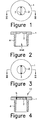
- FIGURE 1 is a top view of a first embodiment of the nozzle pursuant to the present invention.
- FIGURE 2 is a section along the line of 2-2 of Figure 1 ;
- FIGURE 3 is a view as in Figure 1 of a second embodiment
- FIGURE 4 is a section along the lines IV-IV of Figure 3 ;
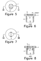
- FIGURE 5 is a view as in Figure 1 of another embodiment
- FIGURE 6 is a section along the line VI-VI of Figure 5 ;
- FIGURE 7 is a view as in Figure 1 of a fourth embodiment of the invention.
- FIGURE 8 is a view along the line VIII-VIII of Figure 7 ;
- FIGURE 9 is a view as in Figure 1 of a fifth embodiment
- FIGURE 10 is a view along line X-X of Figure 9 ;
- FIGURE 11 is a section along the line XI-XI of Figure 12 ;
- FIGURE 12 is a sectional view similar to Figure 2 of a sixth embodiment of the invention.
- FIGURES 13a-c show an inlet side view, an outlet side view, and a sectional view of a nozzle with a first embodiment of a seal
- FIGURES 14a-c are views similar to Figures 13a-c of a further embodiment of a seal
- FIGURES 15a-c show yet another embodiment of a seal
- FIGURES 16a-c show an outlet view and section through a nozzle showing the sealing space between the parts and the parts supported by a bead;
- FIGURES 17a-c are views as in Figures 16a-c of another embodiment
- FIGURES 18a-e show various slot nozzles
- FIGURE 19 shows another embodiment.
- Figs. 1 and 2 show a force-fit nozzle comprising a housing 1, two force-fit parts 2 having a cross section, e.g. segment, equal to the cross section of the housing interior and separated by a rectangular spacer seal 3.
- the parts 2 are force-fit inserted into the housing 1.
- the fluid enters the nozzle via an inlet.
- the housing has a fitting 4 that connects the nozzle with a pipeline.
- the parts can be of any suitable material, such as steel, ceramic, carbon fiber, diamond, etc.
- the spacer seal material can be a brazable material that is later heated after being placed between the parts 2 so as to melt and subsequently solidify to form a seal.
- the material can be melted by induction heating, or by another other suitable heating source.
- the nozzle generates a plane stream with an aspect ratio changing from 1 to 100,000 and generates slot jets having a thickness from several nanometers to several millimeters.
- the shape of the slot jet is determined by the thickness (for example, between 1 micron and 5 mm) of the insert.
- the sealing of the space between the segments and the spacer seal and the segments and the housing is attained by the plastic and elastic deformations of the segments, spacer seal and housing. In order to secure the sealing the housing hardness is less than that of the parts.
- the nozzle is formed by pressing the segments-spacer seal assembly into the housing. The force applied to the assembly constitutes 0-200% of the force needed for deformation of the spacer seal.
- the geometries of the surfaces formed by the exterior of the parts and interior of the housing are almost similar. Small angles of inclination of these surfaces to the nozzle axis have a small difference which determines the elastic and plastic deformation of the nozzle assembly and the housing. This deformation generates forces almost normal to the nozzle axis, which assures sealing of the nozzle.
- the cross sections of the parts are segments
- the interior of the housing may be conical with a generating line having an inclination slightly higher than the generating line of the exterior of the parts.
- other inclinations may be used including where the inclination is lower than the generating line of the exterior of the parts.
- the spacer seal under these conditions works as a sealing agent to assure closing of the space between the surfaces of two parts. At the same time the spacer seal determines the distance between the parts that is the width of the slot and that of the generated jet.
- the nozzle shown in Figs. 3 and 4 contains an additional sealing part.
- the parts or segments 2 and the housing 1 are separated by a conical deformable ring 5, supported by a horizontal shoulder 12.
- the exterior of the parts 2 as well as the interior of the ring 5 can be formed with no inclination, but need not be.
- the deformation is due to the inclination of the interior of the housing 1 and the exterior of the ring 5. In this case ring deformation assures sealing between the housing 1 and the assembly as well as between the assembly parts.
- the cross section of the ring is variable and the ring has the form of an ellipse so that the force exerted by the ring on the segment is minimal at the large ellipse diameter and maximal at the minimal diameter.
- the housing inside has a conical side surface and almost the same angle as the parts 2 ( Fig. 1 ) or the sealing ring 5 ( Figs. 3-6 ).
- the angles of the generating lines of both surfaces are different and may range, for example, without limitation, from 0 (a cylinder) to about 20 degrees.
- Figs. 5 and 6 show a nozzle comprising two or more parts 2 having, e.g., a segment cross section, separated by the spacer seal 3 between each of the parts.
- the parts are force fit inserted into the housing 1 and connected via the fitting 4 with a pipeline which supplies the fluid into the inlet.
- the parts 2 are separated from the housing by the deformable seal 5 and generate n-1 parallel jets, where n is a number of parts 2.
- Figs. 9 and 10 show a nozzle comprising more than two parts 2 having, e.g., a segment cross section where the joint sides of two adjacent parts 2 incline to the nozzle axis at a selected angle and are separated by a spacer seal 3 between the parts.
- the parts are force fit inserted into the housing 1 and connected via the fitting 4 with a pipeline which supplies the fluid into the inlet.
- the parts are separated from the housing by the deformable seal 5 and generate n-1 jets having a desired direction of focusing.
- Figs. 7 and 8 show a nozzle comprising two parts 2 having, e.g., a segment cross section separated by a spacer seal 3 between each of the parts.
- the parts are force fit inserted into the housing 1 and connected via the fitting 4 with a pipeline which supplies the fluid into the inlet.
- the parts are separated from the housing by two deformable seals 5 located at the bottom and the top of the parts and compressed by socket screw 6 with a hole for fluid.
- Formation of a mixing chamber 8 containing two sequential nozzles is shown in Figs. 11-12 .
- the inner nozzle 13 is inserted into the outer nozzle 14.
- the inner nozzle 13 operates as a regular nozzle and supplies a fluid stream into the inlet section of the outer nozzle 14.
- An additional stream into the outer nozzle 14 is supplied via channels 7 between the outer surface of the inner nozzle 13 and the inner surface of the outer nozzle 14. Both streams are mixed in the chamber 8 and form a stream containing uniformly distributed components supplied into the nozzles 13 and 14.
- the slots of the nozzles have coincidental center lines, but the inner nozzle 13 has a smaller aperture (opening) and has channels 7 along the outside surface which fit into the outer nozzle 14 and are used to supply a second fluid or particle, such as an abrasive.
- the inner nozzle 13 has an inside thread for connecting to a pipeline with high pressure liquid.
- the outer nozzle 14 has an outside thread for connecting to a pipeline with fluid or particles which are mixed in the chamber 8 between the two nozzles. This forms a fluid mixture jet.
- the streams to be mixed can also have the opposite direction and impacting jets enter the mixing chamber 8.
- the streams exit the nozzles 13 and 14 and collide in the mixing chamber 8.
- the developed mixture exits via an outlet of the nozzle 14.
- Figs. 13-15 show various ways of sealing of the nozzles comprising the parts 2 separated by spacer seal 3 forming the exit cross section.
- the interior of the housing 1 has a geometry similar to that of the assembly exterior. For example, if the cross sections of the parts 2 are segments, the interior of the cross section of the housing is a circumference.
- the positioning of the assembly can be controlled by a bead 10 that restricts the assembly motion along the nozzle in the direction of flow.
- Figures 13a-c show the case where there is a space between the housing and the assembly.
- Figure 13a is a view from the inlet side of the nozzle.
- Figure13b is a view from the outlet side
- Fig. 13c is a longitudinal section through the nozzle.
- the space between the parts and the housing is filled by a sealing substance such as a glue, special alloy, etc., that can be expanded by heating or by cooling.
- the space can be filled by a shape memory alloy in order to permit on-line control of jet geometry.
- the nozzle is facilitated by a special temperature control system, for example, an induction coil.
- the shape memory alloys can also be used for fabrication of the insertions, parts, bids, etc. This will enable controlling the jet properties on-line.
- Figs. 14a-c show the case where sealing is attained by the fabrication of the parts 2 and the spacer seals 3 with different angles of inclination in order to generate needed elastic forces for a force fit.
- Figs. 15a-c show a nozzle where sealing is attained by the deformation of the parts and the housing.
- the exterior of the nozzle assembly and the conical interior of the housing have similar or substantially similar surfaces that are deformed so that the developed elastic forces are sufficient for nozzle sealing.
- special materials are to be used for fabrication of the parts and spacer seal and housing so that deformation thereof generates the desired stresses within the nozzles.
- the housing can be fabricated out of an elastic material so that the deformation creates the desired elastic forces.
- Figs. 16 and 17 show a nozzle fabricated out of low precision parts.
- the assembly containing the parts 2 and spacer seal 3 (spacer seals) is restricted by two deformed beads 10 and 11.
- the deformation of the beads in Figs. 16a and 16b occurs during the nozzle assembly, as shown in the enlarged view of Fig. 16c , while the bead in Figs. 17a and b is assembly inserted into the housing, as shown in Fig. 17c .
- the deformation of the bead 11 assures sealing of all the elements of the nozzle.
- Figs. 18a-e show various forms of the jet. While the geometry as well as materials of the housing and parts can change in a wide range, the most efficient shapes of the assembly include cross sections that are rectangular, circular or ellipsoidal and a circular or non-circular ring. In the case of the ring opening, the nozzle contains two independent housings, connected by links. The advantage of the rectangular shape is the feasibility to control the jet width off-line by changing the spacer seal or on line by the use of the shape memory alloys for fabrication of the parts of the spacer seal.
- the ring shape jet allows liquid impact based stamping operations. As shown in Fig. 18a , the nozzle outlet has a curved shape.
- Fig. 18c shows a discontinuous outlet
- Fig. 18d shows each of the parts 2 having a toothed construction so that the outlet is formed by open portions on alternate opposite sides of a center line.
- Fig. 18e shows an outlet that is a discontinuous circular or ring annulus.
- FIG 19 there is shown an embodiment in which the parts 2 each have a highly polished surface region that is diffusion bonded to an adjacent polished surface of the other part 2.
- the slot between the parts 2 can be formed by a channel provided in at least one of the parts 2. In this way, when the parts 2 are fusion bonded together the slot is created. Diffusion bonding is known to those skilled in the art and essentially is a bonding of two parts which results from highly polishing surfaces of both the parts so that the parts bond together due only to the polishing of the parts and the placement of the polished surfaces against one another.
- the nozzle is essentially produced by providing two parts which together will form a nozzle, forming a recess in at least one of the parts so that when the parts are placed together a slot will be formed, polishing the surfaces of the parts which will come in contact with one another to a degree so that diffusion bonding will occur when the parts are placed together, and finally placing the parts together into a housing so that diffusion bonding occurs between the contacting highly polished surfaces of the parts.
- a benefit of the diffusion bonding is that the resulting slot is surrounded by the same material on all sides, rather than an inherently softer separating seal as in the previously discussed embodiments. Due to the same material being on each side of the slots, there is a reduced risk of degradation of the slot size taking place during use of the slot.
Landscapes
- Nozzles (AREA)
Claims (33)
- Buse comportant :un corps (1), etun ensemble incluant au moins deux pièces conjuguées déformables (2) séparées par un joint d'espacement (3), l'ensemble étant disposé dans le corps (1) de manière à former une sortie de buse, le corps (1) ou les pièces ou le joint d'espacement (3) étant déformables de manière à définir une géométrie de la sortie de buse et des surfaces de joint entre les pièces (2) et le joint d'espacement (3) et entre les pièces (2) et le corps (1), caractérisé en ce queles pièces (2) et le joint d'espacement (3) sont configurés de sorte qu'une force nécessaire pour insérer l'ensemble dans le corps (1) dépasse une force nécessaire pour une déformation plastique du corps (1) et de l'ensemble.
- Buse selon la revendication 1, dans laquelle le corps (1) est fabriqué à partir d'un matériau ayant une dureté inférieure aux pièces (2) et au joint d'espacement (3).
- Buse selon la revendication 1, dans laquelle le corps (1) est cylindrique, les pièces (2) sont des segments de cercle, et le joint d'espacement (3) est rectangulaire.
- Buse selon la revendication 3, dans laquelle le joint d'espacement (3) a une épaisseur dans une plage inférieure à 5 cm.
- Buse selon la revendication 3, et comportant en outre un anneau déformable (5) disposé entre un épaulement intérieur du corps (1) et l'ensemble de manière à étanchéifier la sortie de la buse.
- Buse selon la revendication 1, dans laquelle un espacement entre les pièces (2) formant la sortie de buse est uniforme.
- Buse selon la revendication 5, et comportant en outre un autre anneau déformable disposé dans le corps contre l'ensemble de manière à étanchéifier une entrée de la buse.
- Buse selon la revendication 3, dans laquelle une pluralité de pièces conjuguées (2) et de joints d'espacement (3) sont disposés en séquence de manière à former des ouvertures parallèles.
- Buse selon la revendication 8, dans laquelle l'ensemble est configuré pour former plusieurs flux qui se concentrent en un point commun.
- Buse selon la revendication 1, dans laquelle le corps (1) a une forme de section transversale interne rectangulaire.
- Buse selon la revendication 1, dans laquelle le corps (1) inclut deux corps qui forment un anneau qui contient l'ensemble.
- Buse selon la revendication 1, dans laquelle les pièces ou le joint d'espacement (3) est/sont constitués d'un alliage à mémoire de forme de telle sorte qu'un contrôle de la température des pièces (2) ou du joint d'espacement (3) fabriqués en alliage à mémoire de forme assure un contrôle direct des propriétés d'un jet sortant par la buse.
- Buse selon la revendication 1, dans laquelle la sortie de buse a une forme incurvée.
- Buse selon la revendication 1, dans laquelle la sortie de buse a une forme de zigzag.
- Buse selon la revendication 1, dans laquelle la sortie de buse est discontinue.
- Buse selon la revendication 1, dans laquelle la sortie de buse est formée par des ouvertures sur des côtés opposés alternés d'une ligne médiane.
- Buse selon la revendication 1, dans laquelle la sortie de buse est un espace annulaire ou circulaire discontinu.
- Buse selon la revendication 1, dans laquelle le joint d'espacement (3) est constitué d'un matériau pouvant être brasé.
- Buse selon la revendication 1, dans laquelle le joint d'espacement (3) est formé par un assemblage par diffusion qui se produit à une interface entre les pièces conjuguées (2).
- Buse selon la revendication 1, dans laquelle le joint d'espacement (3) est un revêtement, un dépôt ou un placage.
- Buse selon la revendication 20, dans laquelle le joint d'espacement (3) est constitué d'or.
- Dispositif de buse, comportant :une première buse intérieure (13) selon l'une des revendications 1 à 21,dans lequel le corps de la première buse intérieure (13) est cylindrique, les pièces (2) sont des segments de cercle, et le joint d'espacement (3) est rectangulaire,une seconde buse extérieure (14) selon l'une des revendications 1 à 21,dans lequel le corps (1) de la seconde buse extérieure (14) est cylindrique, les pièces (2) sont des segments de cercle, et le joint d'espacement (3) est rectangulaire,une entrée de la seconde buse (14) étant en communication fluidique avec la sortie de la première buse (13), etau moins un passage entre le corps de première buse et le corps de seconde buse communiquant avec une chambre de mélange (8) disposée entre la sortie de la première buse et l'entrée de la seconde buse.
- Dispositif de buse selon la revendication 22, dans lequel la chambre de mélange a un canal de sortie qui transporte un mélange de substances délivrées par les deux buses.
- Procédé de formation d'un jet, comportant les étapes consistant à :fournir un corps (1),disposer un ensemble incluant au moins deux pièces conjuguées (2) séparées par un joint d'espacement (3) dans le corps (1) de manière à former une sortie de buse, le corps (1), ou les pièces (2) ou le joint d'espacement (3) étant déformés de manière à définir une géométrie de la sortie de buse et des surfaces de joint entre les pièces (2) et le joint d'espacement (3) et entre les pièces (2) et le corps (1), etdélivrer un fluide à un côté d'entrée du corps, caractérisé en ce quel'étape consistant à disposer l'ensemble dans le corps (1) inclut l'application d'une force à l'ensemble pendant l'insertion dans le corps (1) qui dépasse la force nécessaire pour une déformation plastique du corps (1) et de l'ensemble.
- Procédé selon la revendication 24, incluant la fabrication du corps (1) à partir d'un matériau ayant une dureté inférieure aux pièces (2) et au joint d'espacement (3).
- Procédé selon la revendication 24, incluant en outre l'étape consistant à disposer un anneau déformable entre un épaulement intérieur du corps (1) et l'ensemble de manière à étanchéifier la sortie de buse.
- Procédé selon la revendication 24, incluant la fabrication d'au moins un élément parmi le joint d'espacement (3) et les pièces (2) à partir d'un alliage à mémoire de forme.
- Procédé selon la revendication 26, incluant en outre l'étape consistant à disposer un autre anneau déformable dans le corps contre l'ensemble de manière à étanchéifier une entrée de la buse.
- Procédé selon la revendication 24, dans lequel le joint d'espacement (3) est constitué d'un matériau pouvant être brasé qui est fondu après que l'ensemble ait été disposé dans le corps (1) et ensuite solidifié pour former un joint.
- Procédé selon la revendication 29, dans lequel le joint d'espacement (3) est fondu par un chauffage par induction.
- Procédé selon la revendication 24, incluant un ajustement par retrait ou un ajustement par dilatation des pièces (2) de manière à former un joint lorsque les pièces (2) refroidissent par la suite ou sont chauffées.
- Procédé selon la revendication 24, dans lequel le joint d'espacement (3) est formé par un assemblage par diffusion entre des surfaces opposées des pièces conjuguées.
- Procédé produisant une buse pour former un jet, comportant les étapes consistant à :fournir un corps (1),fournir au moins deux pièces conjuguées (2) avec des surfaces opposées,former un évidement dans au moins une des surfaces, caractérisé par les étapes consistant à :polir les surfaces de sorte qu'un assemblage par diffusion puisse avoir lieu lorsque les surfaces sont placées ensemble, etinsérer les pièces (2) dans le corps (1) de sorte que les surfaces polies entrent en contact l'une avec l'autre, moyennant quoi un assemblage par diffusion se produit pour assembler les surfaces polies des pièces (2) ensemble et former un joint d'espacement (3) entre les pièces (2) de sorte qu'une sortie de buse est formée.
Applications Claiming Priority (2)
| Application Number | Priority Date | Filing Date | Title |
|---|---|---|---|
| US10/803,781 US7185833B2 (en) | 2004-03-18 | 2004-03-18 | Method for fluid jet formation and apparatus for the same |
| US803781 | 2004-03-18 |
Publications (3)
| Publication Number | Publication Date |
|---|---|
| EP1577015A2 EP1577015A2 (fr) | 2005-09-21 |
| EP1577015A3 EP1577015A3 (fr) | 2006-09-06 |
| EP1577015B1 true EP1577015B1 (fr) | 2013-01-02 |
Family
ID=34838928
Family Applications (1)
| Application Number | Title | Priority Date | Filing Date |
|---|---|---|---|
| EP05005949A Expired - Lifetime EP1577015B1 (fr) | 2004-03-18 | 2005-03-18 | Boîtier de buse avec corps de buse inséré à force |
Country Status (2)
| Country | Link |
|---|---|
| US (2) | US7185833B2 (fr) |
| EP (1) | EP1577015B1 (fr) |
Families Citing this family (21)
| Publication number | Priority date | Publication date | Assignee | Title |
|---|---|---|---|---|
| NZ573201A (en) * | 2006-05-19 | 2012-07-27 | Spray Nozzle Eng Pty Ltd | Metallic spray nozzel with a shield retained by the deformation of an outer periphery of a counterbore |
| AU2008212002B2 (en) * | 2007-09-10 | 2012-01-19 | Techtronic Industries Company Limited | Adjustable nozzle for pressure washer |
| US8056837B2 (en) * | 2008-04-25 | 2011-11-15 | Techtronic Outdoor Products Technology Limited | Nozzle for use with a pressure washer |
| EP2442912B1 (fr) * | 2009-06-17 | 2022-07-27 | Spray Nozzle Engineering Pty. Limited | Moyen d'étanchéité de buse de pulvérisation |
| US8171753B2 (en) * | 2009-11-18 | 2012-05-08 | Corning Incorporated | Method for cutting a brittle material |
| US20120273276A1 (en) * | 2011-04-28 | 2012-11-01 | Fishbones AS | Method and Jetting Head for Making a Long and Narrow Penetration in the Ground |
| CA2851541A1 (fr) | 2011-10-12 | 2013-04-18 | Aptargroup, Inc. | Structure de pulverisation en eventail utilisable dans un actionneur de distribution |
| KR101409674B1 (ko) | 2011-11-17 | 2014-06-18 | 이영환 | 금속 나노 입자 제조 장치 |
| US10012425B2 (en) * | 2012-08-29 | 2018-07-03 | Snow Logic, Inc. | Modular dual vector fluid spray nozzles |
| US20150273508A1 (en) * | 2014-03-27 | 2015-10-01 | Stuart Morgan | Brush shower spray nozzle assembly |
| WO2015173698A1 (fr) * | 2014-05-13 | 2015-11-19 | Koninklijke Philips N.V. | Ajutage pour irrigateur buccal comprenant un actionneur d'ajutage dynamique à matériaux sensibles |
| JP6101672B2 (ja) * | 2014-11-29 | 2017-03-22 | マコー株式会社 | ノズル体 |
| GB2533293A (en) | 2014-12-15 | 2016-06-22 | Edwards Ltd | Inlet assembly |
| DE102015213814A1 (de) * | 2015-07-22 | 2017-01-26 | Robert Bosch Gmbh | Einspritzventil, Abgasnachbehandlungssystem |
| US10167085B2 (en) | 2016-01-27 | 2019-01-01 | General Electric Company | Nozzle and vane system for nacelle anti-icing |
| US10513978B2 (en) | 2016-05-02 | 2019-12-24 | General Electric Company | Directed flow nozzle swirl enhancer |
| DE102016114781A1 (de) * | 2016-08-10 | 2018-02-15 | Kraussmaffei Technologies Gmbh | Vorrichtung zum Sprühen eines Auftragungsmaterials mit unterschiedlichen Strahlprofilen |
| EP3587791B1 (fr) * | 2018-06-21 | 2021-03-24 | Claverham Limited | Buse de régulation de débit |
| CN111151390B (zh) * | 2020-01-22 | 2025-02-25 | 柯敏兴 | 一种液体出液形状控制装置 |
| US11701670B2 (en) | 2020-01-26 | 2023-07-18 | Graco Minnesota Inc. | Spray tip |
| USD1055218S1 (en) * | 2023-01-31 | 2024-12-24 | 3M Innovative Properties Company | Adhesive spray nozzle |
Family Cites Families (18)
| Publication number | Priority date | Publication date | Assignee | Title |
|---|---|---|---|---|
| US1133771A (en) * | 1914-09-11 | 1915-03-30 | Otto H L Wernicke | Internal-combustion engine. |
| US1889201A (en) * | 1931-05-09 | 1932-11-29 | Joseph E Holveck | Spray nozzle |
| US2985304A (en) * | 1959-07-31 | 1961-05-23 | Poor & Co | Clamping device for vibrating screen |
| FR1373520A (fr) | 1963-10-31 | 1964-09-25 | Tête de projection notamment pour pulvérisateur ou autres applications, ainsi que les pulvérisateurs ou autres pourvus de ce dispositif ou dispositif similaire | |
| US3447756A (en) * | 1966-09-02 | 1969-06-03 | Robert C Lawrence Jr | Spray nozzle |
| US3447746A (en) * | 1966-10-17 | 1969-06-03 | Emerson Electric Co | Burner control device for a water heater |
| US4258885A (en) * | 1979-03-23 | 1981-03-31 | Legeza Thomas B | Nozzle tip and method of manufacture |
| US4492339A (en) * | 1983-03-02 | 1985-01-08 | Nelson Irrigation Corporation | Flow control nozzle |
| JPH025899Y2 (fr) * | 1984-12-05 | 1990-02-13 | ||
| US4988042A (en) * | 1987-08-12 | 1991-01-29 | Sherman Industries, Inc. | Automated car wash system |
| US5170946A (en) * | 1991-08-22 | 1992-12-15 | Rankin George J | Shaped nozzle for high velocity fluid flow |
| US5307996A (en) * | 1992-08-05 | 1994-05-03 | Takuma Co., Ltd. | Atomizer for slurry fuel |
| DE19518604A1 (de) * | 1995-05-23 | 1996-11-28 | Nordson Corp | Schlitzdüse |
| DE19536903C2 (de) * | 1995-10-04 | 1998-09-10 | Boehringer Ingelheim Int | Vorrichtung zum Haltern eines fluidischen Bauteils |
| FR2772646B1 (fr) | 1997-12-19 | 2000-02-25 | Kuhn Nodet Sa | Buse de pulverisation amelioree |
| AUPP860999A0 (en) | 1999-02-10 | 1999-03-04 | Southern Rubber Pty Ltd | Ultra high pressure liquid jet nozzle |
| US7045934B2 (en) * | 2002-04-11 | 2006-05-16 | Ernest Geskin | Method for jet formation and the apparatus for the same |
| US20040155125A1 (en) * | 2003-02-11 | 2004-08-12 | Kramer Martin S. | High pressure fluid jet nozzles and methods of making |
-
2004
- 2004-03-18 US US10/803,781 patent/US7185833B2/en not_active Expired - Lifetime
-
2005
- 2005-03-18 EP EP05005949A patent/EP1577015B1/fr not_active Expired - Lifetime
-
2006
- 2006-12-19 US US11/612,954 patent/US7510131B2/en not_active Expired - Lifetime
Also Published As
| Publication number | Publication date |
|---|---|
| US20070090208A1 (en) | 2007-04-26 |
| US7185833B2 (en) | 2007-03-06 |
| US7510131B2 (en) | 2009-03-31 |
| EP1577015A3 (fr) | 2006-09-06 |
| EP1577015A2 (fr) | 2005-09-21 |
| US20050205695A1 (en) | 2005-09-22 |
Similar Documents
| Publication | Publication Date | Title |
|---|---|---|
| US7510131B2 (en) | Method for fluid jet formation and apparatus for the same | |
| US11173571B2 (en) | Method and apparatus for cladding a surface of an article | |
| US6899172B2 (en) | Abrasion resistant frac head | |
| RU2415003C2 (ru) | Способ изготовления ребра на свободном конце лопатки, лопатка, полученная при помощи этого способа, и газотурбинный двигатель, оборудованный такой лопаткой | |
| US4648215A (en) | Method and apparatus for forming a high velocity liquid abrasive jet | |
| US7735223B2 (en) | Method of fabricating or repairing a blisk | |
| KR100497268B1 (ko) | 연료 분사 밸브 및 연료 분사 밸브용 밸브시트 제조 방법 | |
| US5785582A (en) | Split abrasive fluid jet mixing tube and system | |
| US6602545B1 (en) | Method of directly making rapid prototype tooling having free-form shape | |
| KR20080081260A (ko) | 커팅헤드 | |
| EP2161353B1 (fr) | Procédé de revêtement utilisant une onde de choc plasma et procédé de fabrication d'une substance revêtue | |
| CN104994963A (zh) | 用于施涂装置的穿孔板以及对应的应用和制造方法 | |
| EP3445570A1 (fr) | Procédé de traitement d'une surface pour l'impression 3d, composant et appareil | |
| US20210178552A1 (en) | Device and method for the surface treatment of a material | |
| JPH04253582A (ja) | 摩擦による削りシステム | |
| US6217670B1 (en) | Method of manufacturing coated fluid tubing | |
| WO2015041613A2 (fr) | Formation d'un tubage de trou de forage par application de couches de matériau au moyen d'une pulvérisation cinétique et dispositif permettant sa réalisation | |
| US11313041B2 (en) | Manufactured metal objects with hollow channels and method for fabrication thereof | |
| US7045934B2 (en) | Method for jet formation and the apparatus for the same | |
| CA2348344C (fr) | Clapet a bille a siege convexe | |
| KR20190004192A (ko) | 초경 공구용 다층 코팅 구조물의 제조 방법 | |
| TW202337586A (zh) | 壓接用衝頭、配置有其之裝置及將部件接合的方法 | |
| US20170008135A1 (en) | Systems and methods for refurbishing a plunger of a gas well system | |
| FR2721536A1 (fr) | Procédé et dispositif de pulvérisation de liquide. | |
| JP2006159348A (ja) | 超高圧水用ノズル及びその製造方法 |
Legal Events
| Date | Code | Title | Description |
|---|---|---|---|
| PUAI | Public reference made under article 153(3) epc to a published international application that has entered the european phase |
Free format text: ORIGINAL CODE: 0009012 |
|
| AK | Designated contracting states |
Kind code of ref document: A2 Designated state(s): AT BE BG CH CY CZ DE DK EE ES FI FR GB GR HU IE IS IT LI LT LU MC NL PL PT RO SE SI SK TR |
|
| AX | Request for extension of the european patent |
Extension state: AL BA HR LV MK YU |
|
| PUAL | Search report despatched |
Free format text: ORIGINAL CODE: 0009013 |
|
| AK | Designated contracting states |
Kind code of ref document: A3 Designated state(s): AT BE BG CH CY CZ DE DK EE ES FI FR GB GR HU IE IS IT LI LT LU MC NL PL PT RO SE SI SK TR |
|
| AX | Request for extension of the european patent |
Extension state: AL BA HR LV MK YU |
|
| 17P | Request for examination filed |
Effective date: 20070123 |
|
| AKX | Designation fees paid |
Designated state(s): AT BE BG CH CY CZ DE DK EE ES FI FR GB GR HU IE IS IT LI LT LU MC NL PL PT RO SE SI SK TR |
|
| 17Q | First examination report despatched |
Effective date: 20091027 |
|
| REG | Reference to a national code |
Ref country code: DE Ref legal event code: R079 Ref document number: 602005037671 Country of ref document: DE Free format text: PREVIOUS MAIN CLASS: B05B0001040000 Ipc: B05B0001020000 |
|
| GRAP | Despatch of communication of intention to grant a patent |
Free format text: ORIGINAL CODE: EPIDOSNIGR1 |
|
| RIC1 | Information provided on ipc code assigned before grant |
Ipc: B05B 1/14 20060101ALI20120705BHEP Ipc: B05B 1/04 20060101ALI20120705BHEP Ipc: B05B 7/04 20060101ALI20120705BHEP Ipc: B05B 1/26 20060101ALI20120705BHEP Ipc: B05B 1/02 20060101AFI20120705BHEP |
|
| GRAS | Grant fee paid |
Free format text: ORIGINAL CODE: EPIDOSNIGR3 |
|
| GRAA | (expected) grant |
Free format text: ORIGINAL CODE: 0009210 |
|
| AK | Designated contracting states |
Kind code of ref document: B1 Designated state(s): AT BE BG CH CY CZ DE DK EE ES FI FR GB GR HU IE IS IT LI LT LU MC NL PL PT RO SE SI SK TR |
|
| REG | Reference to a national code |
Ref country code: GB Ref legal event code: FG4D |
|
| REG | Reference to a national code |
Ref country code: CH Ref legal event code: EP Ref country code: AT Ref legal event code: REF Ref document number: 591277 Country of ref document: AT Kind code of ref document: T Effective date: 20130115 |
|
| REG | Reference to a national code |
Ref country code: IE Ref legal event code: FG4D |
|
| REG | Reference to a national code |
Ref country code: DE Ref legal event code: R096 Ref document number: 602005037671 Country of ref document: DE Effective date: 20130307 |
|
| REG | Reference to a national code |
Ref country code: AT Ref legal event code: MK05 Ref document number: 591277 Country of ref document: AT Kind code of ref document: T Effective date: 20130102 |
|
| REG | Reference to a national code |
Ref country code: NL Ref legal event code: VDEP Effective date: 20130102 |
|
| PG25 | Lapsed in a contracting state [announced via postgrant information from national office to epo] |
Ref country code: SI Free format text: LAPSE BECAUSE OF FAILURE TO SUBMIT A TRANSLATION OF THE DESCRIPTION OR TO PAY THE FEE WITHIN THE PRESCRIBED TIME-LIMIT Effective date: 20130102 |
|
| REG | Reference to a national code |
Ref country code: LT Ref legal event code: MG4D |
|
| PG25 | Lapsed in a contracting state [announced via postgrant information from national office to epo] |
Ref country code: AT Free format text: LAPSE BECAUSE OF FAILURE TO SUBMIT A TRANSLATION OF THE DESCRIPTION OR TO PAY THE FEE WITHIN THE PRESCRIBED TIME-LIMIT Effective date: 20130102 Ref country code: CZ Free format text: LAPSE BECAUSE OF FAILURE TO SUBMIT A TRANSLATION OF THE DESCRIPTION OR TO PAY THE FEE WITHIN THE PRESCRIBED TIME-LIMIT Effective date: 20130102 Ref country code: BG Free format text: LAPSE BECAUSE OF FAILURE TO SUBMIT A TRANSLATION OF THE DESCRIPTION OR TO PAY THE FEE WITHIN THE PRESCRIBED TIME-LIMIT Effective date: 20130402 Ref country code: CY Free format text: LAPSE BECAUSE OF FAILURE TO SUBMIT A TRANSLATION OF THE DESCRIPTION OR TO PAY THE FEE WITHIN THE PRESCRIBED TIME-LIMIT Effective date: 20130102 Ref country code: IS Free format text: LAPSE BECAUSE OF FAILURE TO SUBMIT A TRANSLATION OF THE DESCRIPTION OR TO PAY THE FEE WITHIN THE PRESCRIBED TIME-LIMIT Effective date: 20130502 Ref country code: LT Free format text: LAPSE BECAUSE OF FAILURE TO SUBMIT A TRANSLATION OF THE DESCRIPTION OR TO PAY THE FEE WITHIN THE PRESCRIBED TIME-LIMIT Effective date: 20130102 Ref country code: SE Free format text: LAPSE BECAUSE OF FAILURE TO SUBMIT A TRANSLATION OF THE DESCRIPTION OR TO PAY THE FEE WITHIN THE PRESCRIBED TIME-LIMIT Effective date: 20130102 Ref country code: BE Free format text: LAPSE BECAUSE OF FAILURE TO SUBMIT A TRANSLATION OF THE DESCRIPTION OR TO PAY THE FEE WITHIN THE PRESCRIBED TIME-LIMIT Effective date: 20130102 Ref country code: ES Free format text: LAPSE BECAUSE OF FAILURE TO SUBMIT A TRANSLATION OF THE DESCRIPTION OR TO PAY THE FEE WITHIN THE PRESCRIBED TIME-LIMIT Effective date: 20130413 |
|
| PG25 | Lapsed in a contracting state [announced via postgrant information from national office to epo] |
Ref country code: FI Free format text: LAPSE BECAUSE OF FAILURE TO SUBMIT A TRANSLATION OF THE DESCRIPTION OR TO PAY THE FEE WITHIN THE PRESCRIBED TIME-LIMIT Effective date: 20130102 Ref country code: PL Free format text: LAPSE BECAUSE OF FAILURE TO SUBMIT A TRANSLATION OF THE DESCRIPTION OR TO PAY THE FEE WITHIN THE PRESCRIBED TIME-LIMIT Effective date: 20130102 Ref country code: PT Free format text: LAPSE BECAUSE OF FAILURE TO SUBMIT A TRANSLATION OF THE DESCRIPTION OR TO PAY THE FEE WITHIN THE PRESCRIBED TIME-LIMIT Effective date: 20130502 Ref country code: GR Free format text: LAPSE BECAUSE OF FAILURE TO SUBMIT A TRANSLATION OF THE DESCRIPTION OR TO PAY THE FEE WITHIN THE PRESCRIBED TIME-LIMIT Effective date: 20130403 Ref country code: NL Free format text: LAPSE BECAUSE OF FAILURE TO SUBMIT A TRANSLATION OF THE DESCRIPTION OR TO PAY THE FEE WITHIN THE PRESCRIBED TIME-LIMIT Effective date: 20130102 |
|
| PG25 | Lapsed in a contracting state [announced via postgrant information from national office to epo] |
Ref country code: DK Free format text: LAPSE BECAUSE OF FAILURE TO SUBMIT A TRANSLATION OF THE DESCRIPTION OR TO PAY THE FEE WITHIN THE PRESCRIBED TIME-LIMIT Effective date: 20130102 Ref country code: RO Free format text: LAPSE BECAUSE OF FAILURE TO SUBMIT A TRANSLATION OF THE DESCRIPTION OR TO PAY THE FEE WITHIN THE PRESCRIBED TIME-LIMIT Effective date: 20130102 Ref country code: SK Free format text: LAPSE BECAUSE OF FAILURE TO SUBMIT A TRANSLATION OF THE DESCRIPTION OR TO PAY THE FEE WITHIN THE PRESCRIBED TIME-LIMIT Effective date: 20130102 Ref country code: EE Free format text: LAPSE BECAUSE OF FAILURE TO SUBMIT A TRANSLATION OF THE DESCRIPTION OR TO PAY THE FEE WITHIN THE PRESCRIBED TIME-LIMIT Effective date: 20130102 Ref country code: MC Free format text: LAPSE BECAUSE OF NON-PAYMENT OF DUE FEES Effective date: 20130331 |
|
| REG | Reference to a national code |
Ref country code: CH Ref legal event code: PL |
|
| PLBE | No opposition filed within time limit |
Free format text: ORIGINAL CODE: 0009261 |
|
| STAA | Information on the status of an ep patent application or granted ep patent |
Free format text: STATUS: NO OPPOSITION FILED WITHIN TIME LIMIT |
|
| 26N | No opposition filed |
Effective date: 20131003 |
|
| PG25 | Lapsed in a contracting state [announced via postgrant information from national office to epo] |
Ref country code: IT Free format text: LAPSE BECAUSE OF FAILURE TO SUBMIT A TRANSLATION OF THE DESCRIPTION OR TO PAY THE FEE WITHIN THE PRESCRIBED TIME-LIMIT Effective date: 20130102 |
|
| REG | Reference to a national code |
Ref country code: IE Ref legal event code: MM4A |
|
| REG | Reference to a national code |
Ref country code: DE Ref legal event code: R097 Ref document number: 602005037671 Country of ref document: DE Effective date: 20131003 |
|
| PG25 | Lapsed in a contracting state [announced via postgrant information from national office to epo] |
Ref country code: IE Free format text: LAPSE BECAUSE OF NON-PAYMENT OF DUE FEES Effective date: 20130318 Ref country code: CH Free format text: LAPSE BECAUSE OF NON-PAYMENT OF DUE FEES Effective date: 20130331 Ref country code: LI Free format text: LAPSE BECAUSE OF NON-PAYMENT OF DUE FEES Effective date: 20130331 |
|
| REG | Reference to a national code |
Ref country code: FR Ref legal event code: PLFP Year of fee payment: 11 |
|
| PGFP | Annual fee paid to national office [announced via postgrant information from national office to epo] |
Ref country code: DE Payment date: 20150327 Year of fee payment: 11 |
|
| PGFP | Annual fee paid to national office [announced via postgrant information from national office to epo] |
Ref country code: GB Payment date: 20150327 Year of fee payment: 11 Ref country code: FR Payment date: 20150317 Year of fee payment: 11 |
|
| PG25 | Lapsed in a contracting state [announced via postgrant information from national office to epo] |
Ref country code: TR Free format text: LAPSE BECAUSE OF FAILURE TO SUBMIT A TRANSLATION OF THE DESCRIPTION OR TO PAY THE FEE WITHIN THE PRESCRIBED TIME-LIMIT Effective date: 20130102 |
|
| PG25 | Lapsed in a contracting state [announced via postgrant information from national office to epo] |
Ref country code: HU Free format text: LAPSE BECAUSE OF FAILURE TO SUBMIT A TRANSLATION OF THE DESCRIPTION OR TO PAY THE FEE WITHIN THE PRESCRIBED TIME-LIMIT; INVALID AB INITIO Effective date: 20050318 Ref country code: LU Free format text: LAPSE BECAUSE OF NON-PAYMENT OF DUE FEES Effective date: 20130318 |
|
| REG | Reference to a national code |
Ref country code: DE Ref legal event code: R119 Ref document number: 602005037671 Country of ref document: DE |
|
| GBPC | Gb: european patent ceased through non-payment of renewal fee |
Effective date: 20160318 |
|
| REG | Reference to a national code |
Ref country code: FR Ref legal event code: ST Effective date: 20161130 |
|
| PG25 | Lapsed in a contracting state [announced via postgrant information from national office to epo] |
Ref country code: FR Free format text: LAPSE BECAUSE OF NON-PAYMENT OF DUE FEES Effective date: 20160331 Ref country code: DE Free format text: LAPSE BECAUSE OF NON-PAYMENT OF DUE FEES Effective date: 20161001 Ref country code: GB Free format text: LAPSE BECAUSE OF NON-PAYMENT OF DUE FEES Effective date: 20160318 |