EP1577041A1 - Machine et procédé correspondant de taillage de roues dentées coniques pour la chanfreinage et l'ébavaurage des extrémités de dents des roues dentées coniques - Google Patents
Machine et procédé correspondant de taillage de roues dentées coniques pour la chanfreinage et l'ébavaurage des extrémités de dents des roues dentées coniques Download PDFInfo
- Publication number
- EP1577041A1 EP1577041A1 EP05003817A EP05003817A EP1577041A1 EP 1577041 A1 EP1577041 A1 EP 1577041A1 EP 05003817 A EP05003817 A EP 05003817A EP 05003817 A EP05003817 A EP 05003817A EP 1577041 A1 EP1577041 A1 EP 1577041A1
- Authority
- EP
- European Patent Office
- Prior art keywords
- bevel gear
- bar
- workpiece spindle
- cutter head
- axes
- Prior art date
- Legal status (The legal status is an assumption and is not a legal conclusion. Google has not performed a legal analysis and makes no representation as to the accuracy of the status listed.)
- Granted
Links
- 238000005520 cutting process Methods 0.000 title claims description 43
- 238000000034 method Methods 0.000 title claims description 14
- 238000004519 manufacturing process Methods 0.000 claims description 4
- 238000010924 continuous production Methods 0.000 claims description 3
- 230000008569 process Effects 0.000 claims description 3
- 230000001105 regulatory effect Effects 0.000 abstract 1
- 230000008901 benefit Effects 0.000 description 5
- 238000003801 milling Methods 0.000 description 5
- 230000001154 acute effect Effects 0.000 description 3
- 238000003754 machining Methods 0.000 description 3
- 239000000463 material Substances 0.000 description 3
- 230000008878 coupling Effects 0.000 description 2
- 238000010168 coupling process Methods 0.000 description 2
- 238000005859 coupling reaction Methods 0.000 description 2
- 230000005484 gravity Effects 0.000 description 2
- 238000012935 Averaging Methods 0.000 description 1
- 229910000831 Steel Inorganic materials 0.000 description 1
- 208000027418 Wounds and injury Diseases 0.000 description 1
- 230000009471 action Effects 0.000 description 1
- 238000005253 cladding Methods 0.000 description 1
- 230000006378 damage Effects 0.000 description 1
- 230000002996 emotional effect Effects 0.000 description 1
- 238000005516 engineering process Methods 0.000 description 1
- 230000001771 impaired effect Effects 0.000 description 1
- 208000014674 injury Diseases 0.000 description 1
- 238000009434 installation Methods 0.000 description 1
- 210000002414 leg Anatomy 0.000 description 1
- 238000000465 moulding Methods 0.000 description 1
- 239000010959 steel Substances 0.000 description 1
- 230000007704 transition Effects 0.000 description 1
- 210000000689 upper leg Anatomy 0.000 description 1
Images

Classifications
-
- B—PERFORMING OPERATIONS; TRANSPORTING
- B23—MACHINE TOOLS; METAL-WORKING NOT OTHERWISE PROVIDED FOR
- B23F—MAKING GEARS OR TOOTHED RACKS
- B23F19/00—Finishing gear teeth by other tools than those used for manufacturing gear teeth
- B23F19/10—Chamfering the end edges of gear teeth
-
- B—PERFORMING OPERATIONS; TRANSPORTING
- B23—MACHINE TOOLS; METAL-WORKING NOT OTHERWISE PROVIDED FOR
- B23F—MAKING GEARS OR TOOTHED RACKS
- B23F9/00—Making gears having teeth curved in their longitudinal direction
- B23F9/08—Making gears having teeth curved in their longitudinal direction by milling, e.g. with helicoidal hob
- B23F9/10—Making gears having teeth curved in their longitudinal direction by milling, e.g. with helicoidal hob with a face-mill
-
- B—PERFORMING OPERATIONS; TRANSPORTING
- B23—MACHINE TOOLS; METAL-WORKING NOT OTHERWISE PROVIDED FOR
- B23F—MAKING GEARS OR TOOTHED RACKS
- B23F19/00—Finishing gear teeth by other tools than those used for manufacturing gear teeth
- B23F19/10—Chamfering the end edges of gear teeth
- B23F19/102—Chamfering the end edges of gear teeth by milling
-
- Y—GENERAL TAGGING OF NEW TECHNOLOGICAL DEVELOPMENTS; GENERAL TAGGING OF CROSS-SECTIONAL TECHNOLOGIES SPANNING OVER SEVERAL SECTIONS OF THE IPC; TECHNICAL SUBJECTS COVERED BY FORMER USPC CROSS-REFERENCE ART COLLECTIONS [XRACs] AND DIGESTS
- Y10—TECHNICAL SUBJECTS COVERED BY FORMER USPC
- Y10T—TECHNICAL SUBJECTS COVERED BY FORMER US CLASSIFICATION
- Y10T409/00—Gear cutting, milling, or planing
- Y10T409/10—Gear cutting
- Y10T409/101113—Gear chamfering or deburring
-
- Y—GENERAL TAGGING OF NEW TECHNOLOGICAL DEVELOPMENTS; GENERAL TAGGING OF CROSS-SECTIONAL TECHNOLOGIES SPANNING OVER SEVERAL SECTIONS OF THE IPC; TECHNICAL SUBJECTS COVERED BY FORMER USPC CROSS-REFERENCE ART COLLECTIONS [XRACs] AND DIGESTS
- Y10—TECHNICAL SUBJECTS COVERED BY FORMER USPC
- Y10T—TECHNICAL SUBJECTS COVERED BY FORMER US CLASSIFICATION
- Y10T409/00—Gear cutting, milling, or planing
- Y10T409/10—Gear cutting
- Y10T409/101431—Gear tooth shape generating
- Y10T409/103816—Milling with radial faced tool
- Y10T409/103975—Process
-
- Y—GENERAL TAGGING OF NEW TECHNOLOGICAL DEVELOPMENTS; GENERAL TAGGING OF CROSS-SECTIONAL TECHNOLOGIES SPANNING OVER SEVERAL SECTIONS OF THE IPC; TECHNICAL SUBJECTS COVERED BY FORMER USPC CROSS-REFERENCE ART COLLECTIONS [XRACs] AND DIGESTS
- Y10—TECHNICAL SUBJECTS COVERED BY FORMER USPC
- Y10T—TECHNICAL SUBJECTS COVERED BY FORMER US CLASSIFICATION
- Y10T409/00—Gear cutting, milling, or planing
- Y10T409/10—Gear cutting
- Y10T409/101431—Gear tooth shape generating
- Y10T409/103816—Milling with radial faced tool
- Y10T409/104134—Adapted to cut bevel gear
Definitions
- the present invention relates to gear cutting machines and the Deburring and / or chamfering the tooth edges of bevel gears.
- bevel gears are Devices known for conventional mechanical bevel gear cutting machines were developed. Already during the milling of the Bevel gears in the discontinuous part of the process after each gap Toothed people deburred. Or in the continuous process is after the Gear cutting in a separate operation chamfering and / or deburring performed.
- a deburring device of this type is disclosed in DE 197 44 486 A1 described in the two different cutters, each with its own Have rotary drive, be used for deburring. They are on one arranged common support and work with stationary bevel gear a single radial feed movement.
- the disadvantage here is that the cutter must be aligned with each other and each cutter a special Profile shape of its cutting needs to be deburred to the respective Bevel gear must be adjusted.
- the milling spindle is 3-axis, namely horizontal, vertical and pivotable, relative to the controllable about its axis workpiece carrier movable, and it is a controller for coupling the four axis movements provided, whereby the end mill along a programmed path to be led.
- a separate deburring device are associated with this device, that despite the large mechanical expenditure, the outer tooth ends of lean Schaftritzeln not be chamfered.
- German patent application 11 85 039 A is a Gear machine described in the designated as a planer tool is used, which is attached to a fluid-operated piston.
- a major disadvantage of this known device is that the Planing steel each tooth end only with one adjustable in its direction, but then you can edit in straight cut.
- the to be deburred Profile edge is but a spatially strongly curved curve, resulting from the Section of two surfaces yields, namely the already curved Bevel wheel flank with subsequent foot rounding and the back surface of the Bevel gear tooth.
- the latter is usually a conical surface, which additionally once settled and / or may be rounded at the tooth tip. That means, with the known device can not chamfer the profile edge properly.
- the invention is based on the object, a bevel gear cutting machine to be designed in such a way that you can use a small amount of equipment Effort very different bevel gears, chamfer and / or deburr, and to provide a corresponding method.
- Another object of the invention is a bevel gear cutting machine in such a way that the deburring caused longer residence time of the workpiece in the gear cutting machine is relatively short.
- a Bevel gear cutting machine is provided, among other things, for chamfering and / or deburring edges on the teeth of a bevel gear is designed.
- the gear cutting machine has a workpiece spindle, which is the bevel gear Coaxially receives. It is provided a carriage, which is a plate-shaped Molding knife head with several bar knives.
- the gear machine has a total of at least five numerically controllable axes that have a programmable controller are controlled, one of the axes a Workpiece spindle axis of the workpiece spindle forms. Another axis serves as Tool spindle axis of the plate-shaped cutter head.
- the numeric controllable axes are designed and arranged so that by the Adjusting at least one of the axes, the workpiece spindle including the bevel gear are tiltable relative to the cutter head so that the bar blades at simultaneously rotating the workpiece spindle about the workpiece spindle axis and of the cutter head around the tool spindle axis in succession Immerse interdental spaces between adjacent teeth and a chamfer or Perform deburring movement with respect to the edge.
- the main advantages of the invention are that with the numerically controllable by means of a programmable controller six Axes (NC axes) with almost any shaped profile edges of bevel gears the cutting edge of the bar knife is reached. Thus, despite curved Profile edge generates a chamfer and / or a discount can be made. It Secondary ridge can be avoided because of the steep inclination of the Stabmesser in relation to the bevel gear no large amounts of material must be planed to deburr the full tooth height.
- chamfering or Deburring is done in a continuous process, resulting in much shorter ones Processing times leads to discontinuous processes.
- gear cutting machines can advantageously be used be modified, as in many industrial and manufacturing operations be used.
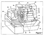
- FIG. 1 is a bevel pinion processed, whereas in Figures 2 and 3, a ring gear is processed.
- Fig. 1 shows a perspective view of the basic structure of a CNC machine 20 for producing curved bevel gears 31.
- Such Machine 20 can be designed or converted according to the invention to a Deburring or chamfering the bevel gear 31 by means of the same bar blades to allow, which also in the manufacture of the teeth of the bevel gear 31 be used.
- the CNC machine 20 may be constructed as follows. On one Machine bed 21 is a machine housing 19 along a straight Coordinate axis X (1st axis) guided horizontally and linearly. A first sled 18 is on a guide 10, which on a side surface of the machine housing 19th is mounted along a straight coordinate axis Z (2nd axis) means a spindle drive 16 in height movable. On the machine bed 21 is a Workpiece spindle carrier 14 with a second carriage 12 along a straight Coordinate axis Y (3rd axis), which is perpendicular to the X-axis, on a Guide 13 horizontally and linearly guided. On the carriage 12 is a Pivoting device 28 with vertical axis C (4th axis). The leadership 10 of first carriage 18 and the Z-axis are inclined to the vertical.
- the first carriage 18 carries one around a tool spindle axis 17 (5. Axis) rotatably mounted tool spindle 11.
- the tool spindle 11 enters Tool, here for example a cutter head 7 with several bar knives.
- a Workpiece spindle 30 is guided horizontally on the machine bed 21 and linear displaceable or pivotable.
- the Schenkvorraum 28 carries the Workpiece spindle 30 which is rotatable about a workpiece spindle axis 32 (6th axis) is.
- the workpiece spindle 30 carries a workpiece 31, in the present example an arc-toothed bevel pinion.
- the pivoting device 28 is about the C-axis guided horizontally pivotable to the workpiece 31 in a Pivoting machining position and, if necessary, movements during to carry out the chamfering and / or deburring according to the invention.
- the machine 20 thus has six numerically controlled Axes up.
- be Machines with at least five numerically controlled axes are preferred.
- the Machine bed 21 recessed and a chip collector 35 arranged in the Chips, which occur during chamfering and / or deburring, essentially by Get gravity.
- a panel 37 fixed to the machine bed 21st is connected and between the machine housing 19 and the second Carriage 12 is arranged.
- the panel 37 is by a bellows 38 with connected to the machine housing 19.
- the panel 37 and the bellows 38 are also sloping towards the chip collector 35.
- a shield 39 which the Pivoting device 28 surrounds semicircular and on the second carriage 12th is attached.
- a hinted CNC control 29 ensures that the six numerically controlled axes used for deburring or chamfering perform necessary movements after the gear cutting process is completed.
- the relative inclination between the dish-shaped cutter head 7 and the end face of the bevel gear 1 increases, as can be seen in Figures 2 and 3.
- in the upper part of Fig. 2 is a plan view of a plate-shaped cutter head 7 with several bar knives 3 and 4 shown.
- the bar blades 3, 4 are in the upper part 2 indicated only because they are located on the side of the cutter head 7, which faces the workpiece 1.
- the bar blades 3 and 4 are alternating arranged on the cutter head, wherein the bar blade 3, for example, the convex flank 1.1 of a tooth and the bar blade 4, for example, the concave Edge 1.2 of a tooth processed.
- Fig. 2 is a schematic side view shown. In this side view you can see that the bar blades 3, 4 stuck in the cutter head 7 and by the slight relative Inclination between the cutter head 7 and a radial section of the bevel gear. 1 dive into the tooth spaces on the right side and there the convex and form concave tooth flanks.
- the installation position of the cutter head 7 and the Bevel gear 1 in the gear cutting machine 20 can be seen from the Work spindle axis 32 and the tool spindle axis 17 recognize.
- the projection of the workpiece spindle axis 32 closes on the Tool spindle axis 17 an angle a between 0 and 70 degrees, as shown in FIG. 2 indicated.
- a larger angle a is set, which is preferably one Angular difference between 10 and 60 degrees deviates from that angle, the was used when milling the same bevel gear.
- a plate-shaped cutter head 7 with several Bar knives 3 and 4 shown, which are used for deburring.
- the Stabmesser 3 and 4 dive one after the other in successive Tooth gaps, as shown in the lower part of Fig. 3, wherein by the extreme Slope (inclination) is swept over only one end of the tooth gaps.
- the inclination is set and the axes are moved so that only the concave tooth flanks are deburred be, as, as described above, these flanks with the back surface of the Bevel gear usually forming an acute angle. It only comes those bar cutters for cutting, used to make the concave flanks be used. Every second bar knife becomes in this embodiment skipped during deburring, i. between him and the tooth flank does not occur Contact on.
- the machine settings be chosen so that the bar blade 3 any burrs on a convex Flank removed and the bar blade 4 any burrs on a concave flank away.
- the workpiece spindle 30 and the tool spindle 11 arranged so that when gearing and deburring or chamfering the Workpiece 31 and the tool 7 substantially over the area of Machine 20 are located where the resulting chips easily collected can be. If a machine according to FIG. 1 is used, then it is too mention that the chips that arise during chamfering or deburring in Essentially reach the chip collector 35 by gravity.
- the same Tool 7 is used, which also already for machining the Workpiece 31 was used.
- To chamfer or deburr is made possible by adjusting at least one of the axes of the Machine 20, the workpiece spindle 30 together with the bevel gear 31 relative to the Cutter head strongly inclined, as shown in Fig. 3.
- To make a coordinated rotation of the To enable workpiece spindle 30 and the cutter head 7 are through the Control 29 coupled at least these two rotational movements.
- a rotation about the vertical C-axis as can be illustrated by the machine 20 in Fig. 1.
- the inclination be adjusted between bevel gear 31 and cutter head 7.
- suitable rotational speeds rotational movements of the bevel gear 31 about the workpiece spindle axis 32 and the cutter head 7 to the Tool spindle axis 17 executed, so the inventive Deburring.
- the adjustment of the Axes are dynamically made to ensure that the bar knives only in the End of the teeth to be deburred come into contact and become active.
- the controller 29 a part of the axis movements or all movements of the six numerically controlled axes coupled.
- a first pass the Deburring done.
- the relative inclination of the Knife head 7 to the workpiece 1 adjusted so that the bar knives only burrs remove, which stand away from the tooth edges.
- a chamfer is generated.
- the programmable controls Control the axes so that the bar knives at the desired angle Edit tooth edges that have been previously deburred. It is possible Secondary ridge avoid there with appropriate steep slope of the bar knife In relation to the bevel gear no large amounts of material are machined need to deburr to the full tooth height.
- the bar knives are not special Profile shape of the cutting need to according to the invention for deburring or Chamfering can be used. So you have to chamfer before or Deburring does not clamp new tools nor does it have to be deburred Workpiece to be transferred to another machine. It can according to Invention machined and chamfered with the same workpiece clamping or be deburred. This results in enormous time savings.
- the profile edge to be deburred is curved with bevel gears Gearing a spatially highly curved curve resulting from the cut results in two surfaces, namely the already curved edge with subsequent foot rounding and the back surface of the bevel gear tooth.
- Such a profile edge with a highly curved curve can advantageously be chamfered or deburred with a device according to the invention, since let the six axes of the machine control so that the cutting edges of the machine Bar knives within certain limits can move freely to the profile edge.
- the gear cutting machine is designed as in FIG. 1 shown.
- Such an arrangement of the six axes makes it possible that the Area in which the engagement point of workpiece 31 and tool 7 is large enough to greatly tilt the bevel gear 31 with respect to to allow the dish-shaped tool 7, without causing any obstructions or collisions comes.
- the gear cutting machine 20 is programmable Control 29 equipped, which allows the adjustment of the axes so that can be deburred or chamfered.
- the programmable Control designed so that at least two of the six numerically controllable Axes are coupled in terms of movement. Particularly preferred is the coupling of five or even six of the numerically controlled axes.
- the programmable controller designed so that it allows the movement Controls that the bar knives only in the end area of the interdental spaces plunge.
- a cable is indicated that provided with the number 27 is.
- the entire control or part of the control to be outsourced would be sent via the cable 27 to the Gear machine 20 are handed over.
- the invention can be controlled particularly advantageously in a CNC Gear cutting machine according to DE19646189 C2 be used.
Landscapes
- Engineering & Computer Science (AREA)
- Mechanical Engineering (AREA)
- Gear Processing (AREA)
Applications Claiming Priority (2)
| Application Number | Priority Date | Filing Date | Title |
|---|---|---|---|
| DE202004004480U | 2004-03-19 | ||
| DE202004004480U DE202004004480U1 (de) | 2004-03-19 | 2004-03-19 | Kegelrad-Verzahnmaschine zum Anfasen und/oder Entgraten von Kanten an den Zähnen eines Kegelrades |
Publications (2)
| Publication Number | Publication Date |
|---|---|
| EP1577041A1 true EP1577041A1 (fr) | 2005-09-21 |
| EP1577041B1 EP1577041B1 (fr) | 2009-05-13 |
Family
ID=32478515
Family Applications (1)
| Application Number | Title | Priority Date | Filing Date |
|---|---|---|---|
| EP05003817A Expired - Lifetime EP1577041B1 (fr) | 2004-03-19 | 2005-02-23 | Machine et procédé correspondant de taillage de roues dentées coniques pour la chanfreinage et l'ébavaurage des extrémités de dents des roues dentées coniques |
Country Status (8)
| Country | Link |
|---|---|
| US (1) | US7422397B2 (fr) |
| EP (1) | EP1577041B1 (fr) |
| JP (1) | JP4843238B2 (fr) |
| KR (1) | KR101254793B1 (fr) |
| CN (1) | CN100542724C (fr) |
| AT (1) | ATE431213T1 (fr) |
| DE (2) | DE202004004480U1 (fr) |
| ES (1) | ES2323788T3 (fr) |
Families Citing this family (24)
| Publication number | Priority date | Publication date | Assignee | Title |
|---|---|---|---|---|
| CN100491036C (zh) * | 2005-12-20 | 2009-05-27 | 许晓华 | 齿轮去毛刺设备 |
| JP5156020B2 (ja) * | 2006-09-06 | 2013-03-06 | ザ グリーソン ワークス | 歯車試験およびラップ加工機械 |
| JP2008149328A (ja) * | 2006-12-14 | 2008-07-03 | Shiga Yamashita:Kk | 鋳物用仕上げ装置 |
| US8967926B2 (en) * | 2008-06-23 | 2015-03-03 | The Gleason Works | Manufacturing bevel gears |
| EP2480366B1 (fr) * | 2009-09-25 | 2013-11-06 | The Gleason Works | Dispositif pour chanfreiner et/ou ébarber les engrenages |
| US20110116885A1 (en) * | 2009-11-13 | 2011-05-19 | Chunliang Hsiao | Face hob hypoid gear tooth top-land radius by common chamfer tool |
| CN101829815B (zh) * | 2010-05-10 | 2012-07-25 | 天津精诚机床股份有限公司 | 一种锥齿轮齿顶加工方法及锥齿轮齿顶倒角机 |
| CN102909555B (zh) * | 2011-08-05 | 2015-11-25 | 先生精机株式会社 | 加工装置 |
| CN102294519B (zh) * | 2011-08-22 | 2013-05-01 | 江苏双环齿轮有限公司 | 铣齿机用自动去毛刺装置 |
| KR101383297B1 (ko) * | 2013-09-12 | 2014-04-09 | 금오공과대학교 산학협력단 | 수치제어를 이용한 다축 디버링 장치 |
| DE102014007646A1 (de) * | 2014-05-23 | 2015-11-26 | Liebherr-Verzahntechnik Gmbh | Verfahren zur Lagebestimmung der Evolventen bei Verzahnungen |
| DE102014218082B4 (de) * | 2014-09-10 | 2016-11-10 | Felsomat Gmbh & Co. Kg | Vorrichtung zur Wälzschälbearbeitung eines Werkstücks zur Fertigung einer Fase und zugehöriges Betriebsverfahren |
| CN104625243A (zh) * | 2015-02-11 | 2015-05-20 | 温岭市宇弘机械设备有限公司 | 数控双铣刀齿轮铣棱机 |
| DE102015012603A1 (de) * | 2015-09-28 | 2017-03-30 | Liebherr-Verzahntechnik Gmbh | Verfahren zum Entgraten eines Zahnradrohlings |
| US10295039B2 (en) | 2016-02-04 | 2019-05-21 | Sikorsky Aircraft Corporation | Convex gear tooth edge break |
| DE102016117962A1 (de) | 2016-09-23 | 2018-03-29 | Klingelnberg Ag | Kegelrad-Verzahnmaschine zum Anfasen von Kegelradzahnkanten und Verfahren zum Anfasen der Zahnkanten von Kegelrädern |
| EP3375555B1 (fr) | 2017-03-17 | 2024-07-24 | Klingelnberg AG | Procédé de traitement des flancs de dent de pièces de roue dentée conique |
| EP3517235B1 (fr) * | 2018-01-25 | 2020-12-09 | Klingelnberg GmbH | Procédé d'ébarbage de pignons conique et machine à tailler les engrenages cnc pourvue d'un logiciel d'ébarbage correspondant |
| DE102018108635A1 (de) * | 2018-04-11 | 2019-10-17 | Klingelnberg Gmbh | Verfahren zum entgrat-bürsten von zahnrädern |
| CN109317765A (zh) * | 2018-11-20 | 2019-02-12 | 宝鸡虢西磨棱机制造有限公司 | 一种移动工作台弧齿锥齿齿轮倒角机 |
| ES3036229T3 (en) * | 2019-09-16 | 2025-09-16 | Reishauer Ag | Machine tool for machining teeth, method for machining tooth flanks of a workpiece, and method for dressing a tool for machining teeth using a machine tool of this type |
| WO2021055769A1 (fr) * | 2019-09-18 | 2021-03-25 | Massachusetts Institute Of Technology | Systèmes, compositions, et procédés de production de bords tranchants |
| DE102019131266A1 (de) * | 2019-11-20 | 2021-05-20 | Schaeffler Technologies AG & Co. KG | Verfahren und Vorrichtung zum Entgraten eines innenverzahnten Werkstücks |
| JP6955293B1 (ja) * | 2021-02-08 | 2021-10-27 | 株式会社クロイツ | バリ取ツール、バリ取装置及びバリ取システム |
Citations (5)
| Publication number | Priority date | Publication date | Assignee | Title |
|---|---|---|---|---|
| DE4319326A1 (de) * | 1993-06-11 | 1994-12-15 | Werner Hermann Wera Werke | Verfahren und Vorrichtung zum Verzahnen und Abdachen von Zahnflanken |
| JPH0724635A (ja) * | 1993-06-30 | 1995-01-27 | Yutaka Seimitsu Kogyo Kk | まがり歯かさ歯車の面取り加工方法 |
| DE19646189A1 (de) * | 1996-11-08 | 1998-05-14 | Klingelnberg Soehne Gmbh | Maschine zum Herstellen von bogenverzahnten Kegelrädern |
| DE19900423A1 (de) * | 1998-01-28 | 1999-08-05 | Werner Hermann Wera Werke | Vorrichtung zum Entgraten der Zahnflanken stirnverzahnter Zahnräder oder dergleichen sowie Verfahren dazu |
| DE20103328U1 (de) * | 2001-02-24 | 2001-05-23 | Klingelnberg Söhne GmbH, 42499 Hückeswagen | Entgratvorrichtung für Kegelräder |
Family Cites Families (8)
| Publication number | Priority date | Publication date | Assignee | Title |
|---|---|---|---|---|
| US2772602A (en) * | 1951-03-30 | 1956-12-04 | John M Christman | Apparatus for manufacturing spiral bevel and hypoid gears |
| DE1185039B (de) | 1961-08-17 | 1965-01-07 | Gleason Works | Vorrichtung zum Entgraten und Brechen der stirnseitigen Kanten von Zahnradzaehnen |
| JP3017503B2 (ja) * | 1989-04-28 | 2000-03-13 | トヨタ自動車株式会社 | 万能歯車面取り盤 |
| JP2588353B2 (ja) * | 1993-01-26 | 1997-03-05 | 豊精密工業株式会社 | 歯車加工装置 |
| JPH10180542A (ja) | 1996-12-27 | 1998-07-07 | Nissan Motor Co Ltd | 歯車の面取り加工方法および面取り加工装置 |
| DE19744486C2 (de) | 1997-10-09 | 2000-01-13 | Mhd Maschinenservice Gmbh | Fräsvorrichtung zum Anfasen und Entgraten von schräg- und/oder bogenverzahnten Kegelrädern |
| JP2002046030A (ja) * | 2000-08-04 | 2002-02-12 | Yutaka Seimitsu Kogyo Ltd | 傘状歯車の製造方法,傘状歯車用素材および傘状歯車 |
| JP2003251527A (ja) | 2002-02-27 | 2003-09-09 | Toyota Motor Corp | 曲歯傘歯車の歯形成形装置と歯形成形方法 |
-
2004
- 2004-03-19 DE DE202004004480U patent/DE202004004480U1/de not_active Expired - Lifetime
-
2005
- 2005-02-23 AT AT05003817T patent/ATE431213T1/de active
- 2005-02-23 ES ES05003817T patent/ES2323788T3/es not_active Expired - Lifetime
- 2005-02-23 EP EP05003817A patent/EP1577041B1/fr not_active Expired - Lifetime
- 2005-02-23 DE DE502005007259T patent/DE502005007259D1/de not_active Expired - Lifetime
- 2005-03-11 KR KR1020050020604A patent/KR101254793B1/ko not_active Expired - Fee Related
- 2005-03-18 JP JP2005078820A patent/JP4843238B2/ja not_active Expired - Fee Related
- 2005-03-18 US US11/083,616 patent/US7422397B2/en not_active Expired - Fee Related
- 2005-03-18 CN CNB2005100592217A patent/CN100542724C/zh not_active Expired - Fee Related
Patent Citations (5)
| Publication number | Priority date | Publication date | Assignee | Title |
|---|---|---|---|---|
| DE4319326A1 (de) * | 1993-06-11 | 1994-12-15 | Werner Hermann Wera Werke | Verfahren und Vorrichtung zum Verzahnen und Abdachen von Zahnflanken |
| JPH0724635A (ja) * | 1993-06-30 | 1995-01-27 | Yutaka Seimitsu Kogyo Kk | まがり歯かさ歯車の面取り加工方法 |
| DE19646189A1 (de) * | 1996-11-08 | 1998-05-14 | Klingelnberg Soehne Gmbh | Maschine zum Herstellen von bogenverzahnten Kegelrädern |
| DE19900423A1 (de) * | 1998-01-28 | 1999-08-05 | Werner Hermann Wera Werke | Vorrichtung zum Entgraten der Zahnflanken stirnverzahnter Zahnräder oder dergleichen sowie Verfahren dazu |
| DE20103328U1 (de) * | 2001-02-24 | 2001-05-23 | Klingelnberg Söhne GmbH, 42499 Hückeswagen | Entgratvorrichtung für Kegelräder |
Non-Patent Citations (1)
| Title |
|---|
| PATENT ABSTRACTS OF JAPAN vol. 1995, no. 04 31 May 1995 (1995-05-31) * |
Also Published As
| Publication number | Publication date |
|---|---|
| DE502005007259D1 (de) | 2009-06-25 |
| CN100542724C (zh) | 2009-09-23 |
| US7422397B2 (en) | 2008-09-09 |
| ES2323788T3 (es) | 2009-07-24 |
| CN1669709A (zh) | 2005-09-21 |
| KR20060044312A (ko) | 2006-05-16 |
| US20050207858A1 (en) | 2005-09-22 |
| JP4843238B2 (ja) | 2011-12-21 |
| JP2005262439A (ja) | 2005-09-29 |
| DE202004004480U1 (de) | 2004-06-03 |
| EP1577041B1 (fr) | 2009-05-13 |
| KR101254793B1 (ko) | 2013-04-15 |
| ATE431213T1 (de) | 2009-05-15 |
Similar Documents
| Publication | Publication Date | Title |
|---|---|---|
| EP1577041B1 (fr) | Machine et procédé correspondant de taillage de roues dentées coniques pour la chanfreinage et l'ébavaurage des extrémités de dents des roues dentées coniques | |
| DE102009020771C9 (de) | Bearbeitungsvorrichtung und Bearbeitungsverfahren zur spanabtragenden Bearbeitung komplex gekrümmter Werkstückkanten an Werkstücken | |
| EP2367656B1 (fr) | Machine-outil et procédé de fabrication de dentures | |
| EP1598137B1 (fr) | Machine de taillage de roues dentées coniques pour chanfreiner et/ou ébavurer une roue dentée ainsi qu'un procédé correspondant | |
| EP3552743B1 (fr) | Dispositif et procédé de chanfreinage d'une pièce dentée | |
| EP3299105B1 (fr) | Procédé de chanfreinage des roues dentées coniques | |
| EP0107826B1 (fr) | Machine-outil pour le fraisage simultané de plusieurs surfaces des extrémités libres d'une pièce | |
| EP3230001B1 (fr) | Procédé de traitement d'une denture, ensemble d'outil et machine à denture | |
| EP1745877B1 (fr) | Machine de taillage de roues dentées, notamment machine de taillage de roues dentées coniques, avec un dispositif pour la chanfreiner et l' ébavurer des extrémités de dents des roues dentées | |
| DE10256222B4 (de) | Maschine und Verfahren mit 7 Achsen zum CNC-gesteuerten spanabhebenden Bearbeiten, insbesondere Wälzfräsen oder Wälzschleifen, von Spiralkegelrädern | |
| EP3412393B1 (fr) | Dispositifs et procédé de chanfreinage d'une pièce à denture intérieure | |
| DE102007051375A1 (de) | Bearbeitungsmaschine zum Bearbeiten eines Werkstücks | |
| EP3388179A1 (fr) | Procédé d'usinage de denture d'une pièce à usiner | |
| DE102018001477A1 (de) | Anfaswerkzeug und Verfahren zum Anfasen von Verzahnungen | |
| EP3412395A2 (fr) | Dispositifs et procédé de chanfreinage d'une pièce à denture intérieure | |
| WO2017174187A1 (fr) | Procédé d'enlèvement de matière d'une arête frontale de denture d'engrenage et dispositif conçu à cet effet | |
| DE102018113323A1 (de) | Zahnradbearbeitungsverfahren und Zahnradbearbeitungsgerät | |
| WO2014131488A1 (fr) | Procédé de fabrication ou d'usinage par enlèvement de matière d'une denture, et machine de taillage d'engrenages | |
| DE102015012190B3 (de) | Wälzfräsmaschine zum Herstellen und Entgraten von Verzahnungen | |
| DE102015015810A1 (de) | Verfahren zum Erzeugen oder Bearbeiten von Verzahnungen und dazu ausgelegte Verzahnungsmaschine | |
| EP0568849A1 (fr) | Procédé pour le finissage des dents de roues dentées ayant une denture bombée ou conique et machine pour la mise en oeuvre de ce procédé | |
| EP4615652A1 (fr) | Procédé d'usinage de denture avec chanfreinage ultérieur | |
| DE10109117C1 (de) | Entgratvorrichtung für Kegelräder | |
| DE3520521A1 (de) | Maschine zum spanenden einarbeiten der spanraumnuten von laenglichen, am umfang schneidenden werkzeugen mit halbkugelfoermigem ende | |
| DE102017129651A1 (de) | Verfahren zur Verzahnbearbeitung eines Werkstücks |
Legal Events
| Date | Code | Title | Description |
|---|---|---|---|
| PUAI | Public reference made under article 153(3) epc to a published international application that has entered the european phase |
Free format text: ORIGINAL CODE: 0009012 |
|
| AK | Designated contracting states |
Kind code of ref document: A1 Designated state(s): AT BE BG CH CY CZ DE DK EE ES FI FR GB GR HU IE IS IT LI LT LU MC NL PL PT RO SE SI SK TR |
|
| AX | Request for extension of the european patent |
Extension state: AL BA HR LV MK YU |
|
| 17P | Request for examination filed |
Effective date: 20051027 |
|
| AKX | Designation fees paid |
Designated state(s): AT BE BG CH CY CZ DE DK EE ES FI FR GB GR HU IE IS IT LI LT LU MC NL PL PT RO SE SI SK TR |
|
| 17Q | First examination report despatched |
Effective date: 20061108 |
|
| GRAP | Despatch of communication of intention to grant a patent |
Free format text: ORIGINAL CODE: EPIDOSNIGR1 |
|
| GRAS | Grant fee paid |
Free format text: ORIGINAL CODE: EPIDOSNIGR3 |
|
| GRAA | (expected) grant |
Free format text: ORIGINAL CODE: 0009210 |
|
| R17C | First examination report despatched (corrected) |
Effective date: 20061108 |
|
| AK | Designated contracting states |
Kind code of ref document: B1 Designated state(s): AT BE BG CH CY CZ DE DK EE ES FI FR GB GR HU IE IS IT LI LT LU MC NL PL PT RO SE SI SK TR |
|
| REG | Reference to a national code |
Ref country code: GB Ref legal event code: FG4D Free format text: NOT ENGLISH |
|
| REG | Reference to a national code |
Ref country code: CH Ref legal event code: EP |
|
| REG | Reference to a national code |
Ref country code: CH Ref legal event code: NV Representative=s name: OK PAT AG PATENTE MARKEN LIZENZEN |
|
| REG | Reference to a national code |
Ref country code: IE Ref legal event code: FG4D |
|
| REF | Corresponds to: |
Ref document number: 502005007259 Country of ref document: DE Date of ref document: 20090625 Kind code of ref document: P |
|
| REG | Reference to a national code |
Ref country code: ES Ref legal event code: FG2A Ref document number: 2323788 Country of ref document: ES Kind code of ref document: T3 |
|
| REG | Reference to a national code |
Ref country code: SE Ref legal event code: TRGR |
|
| PG25 | Lapsed in a contracting state [announced via postgrant information from national office to epo] |
Ref country code: PT Free format text: LAPSE BECAUSE OF FAILURE TO SUBMIT A TRANSLATION OF THE DESCRIPTION OR TO PAY THE FEE WITHIN THE PRESCRIBED TIME-LIMIT Effective date: 20090913 Ref country code: LT Free format text: LAPSE BECAUSE OF FAILURE TO SUBMIT A TRANSLATION OF THE DESCRIPTION OR TO PAY THE FEE WITHIN THE PRESCRIBED TIME-LIMIT Effective date: 20090513 |
|
| PG25 | Lapsed in a contracting state [announced via postgrant information from national office to epo] |
Ref country code: IS Free format text: LAPSE BECAUSE OF FAILURE TO SUBMIT A TRANSLATION OF THE DESCRIPTION OR TO PAY THE FEE WITHIN THE PRESCRIBED TIME-LIMIT Effective date: 20090913 Ref country code: PL Free format text: LAPSE BECAUSE OF FAILURE TO SUBMIT A TRANSLATION OF THE DESCRIPTION OR TO PAY THE FEE WITHIN THE PRESCRIBED TIME-LIMIT Effective date: 20090513 Ref country code: SI Free format text: LAPSE BECAUSE OF FAILURE TO SUBMIT A TRANSLATION OF THE DESCRIPTION OR TO PAY THE FEE WITHIN THE PRESCRIBED TIME-LIMIT Effective date: 20090513 |
|
| REG | Reference to a national code |
Ref country code: IE Ref legal event code: FD4D |
|
| PG25 | Lapsed in a contracting state [announced via postgrant information from national office to epo] |
Ref country code: EE Free format text: LAPSE BECAUSE OF FAILURE TO SUBMIT A TRANSLATION OF THE DESCRIPTION OR TO PAY THE FEE WITHIN THE PRESCRIBED TIME-LIMIT Effective date: 20090513 Ref country code: CZ Free format text: LAPSE BECAUSE OF FAILURE TO SUBMIT A TRANSLATION OF THE DESCRIPTION OR TO PAY THE FEE WITHIN THE PRESCRIBED TIME-LIMIT Effective date: 20090513 Ref country code: RO Free format text: LAPSE BECAUSE OF FAILURE TO SUBMIT A TRANSLATION OF THE DESCRIPTION OR TO PAY THE FEE WITHIN THE PRESCRIBED TIME-LIMIT Effective date: 20090513 Ref country code: DK Free format text: LAPSE BECAUSE OF FAILURE TO SUBMIT A TRANSLATION OF THE DESCRIPTION OR TO PAY THE FEE WITHIN THE PRESCRIBED TIME-LIMIT Effective date: 20090513 Ref country code: IE Free format text: LAPSE BECAUSE OF FAILURE TO SUBMIT A TRANSLATION OF THE DESCRIPTION OR TO PAY THE FEE WITHIN THE PRESCRIBED TIME-LIMIT Effective date: 20090513 |
|
| PG25 | Lapsed in a contracting state [announced via postgrant information from national office to epo] |
Ref country code: SK Free format text: LAPSE BECAUSE OF FAILURE TO SUBMIT A TRANSLATION OF THE DESCRIPTION OR TO PAY THE FEE WITHIN THE PRESCRIBED TIME-LIMIT Effective date: 20090513 |
|
| PLBE | No opposition filed within time limit |
Free format text: ORIGINAL CODE: 0009261 |
|
| STAA | Information on the status of an ep patent application or granted ep patent |
Free format text: STATUS: NO OPPOSITION FILED WITHIN TIME LIMIT |
|
| PG25 | Lapsed in a contracting state [announced via postgrant information from national office to epo] |
Ref country code: BG Free format text: LAPSE BECAUSE OF FAILURE TO SUBMIT A TRANSLATION OF THE DESCRIPTION OR TO PAY THE FEE WITHIN THE PRESCRIBED TIME-LIMIT Effective date: 20090813 |
|
| 26N | No opposition filed |
Effective date: 20100216 |
|
| PG25 | Lapsed in a contracting state [announced via postgrant information from national office to epo] |
Ref country code: MC Free format text: LAPSE BECAUSE OF NON-PAYMENT OF DUE FEES Effective date: 20100301 Ref country code: GR Free format text: LAPSE BECAUSE OF FAILURE TO SUBMIT A TRANSLATION OF THE DESCRIPTION OR TO PAY THE FEE WITHIN THE PRESCRIBED TIME-LIMIT Effective date: 20090814 |
|
| PG25 | Lapsed in a contracting state [announced via postgrant information from national office to epo] |
Ref country code: CY Free format text: LAPSE BECAUSE OF FAILURE TO SUBMIT A TRANSLATION OF THE DESCRIPTION OR TO PAY THE FEE WITHIN THE PRESCRIBED TIME-LIMIT Effective date: 20090513 |
|
| PG25 | Lapsed in a contracting state [announced via postgrant information from national office to epo] |
Ref country code: HU Free format text: LAPSE BECAUSE OF FAILURE TO SUBMIT A TRANSLATION OF THE DESCRIPTION OR TO PAY THE FEE WITHIN THE PRESCRIBED TIME-LIMIT Effective date: 20091114 Ref country code: LU Free format text: LAPSE BECAUSE OF NON-PAYMENT OF DUE FEES Effective date: 20100223 |
|
| PG25 | Lapsed in a contracting state [announced via postgrant information from national office to epo] |
Ref country code: TR Free format text: LAPSE BECAUSE OF FAILURE TO SUBMIT A TRANSLATION OF THE DESCRIPTION OR TO PAY THE FEE WITHIN THE PRESCRIBED TIME-LIMIT Effective date: 20090513 |
|
| REG | Reference to a national code |
Ref country code: FR Ref legal event code: PLFP Year of fee payment: 12 |
|
| REG | Reference to a national code |
Ref country code: FR Ref legal event code: PLFP Year of fee payment: 13 |
|
| PGFP | Annual fee paid to national office [announced via postgrant information from national office to epo] |
Ref country code: FI Payment date: 20170213 Year of fee payment: 13 Ref country code: FR Payment date: 20170217 Year of fee payment: 13 Ref country code: DE Payment date: 20170217 Year of fee payment: 13 Ref country code: CH Payment date: 20170217 Year of fee payment: 13 Ref country code: SE Payment date: 20170216 Year of fee payment: 13 |
|
| PGFP | Annual fee paid to national office [announced via postgrant information from national office to epo] |
Ref country code: GB Payment date: 20170216 Year of fee payment: 13 Ref country code: AT Payment date: 20170217 Year of fee payment: 13 Ref country code: BE Payment date: 20170216 Year of fee payment: 13 Ref country code: NL Payment date: 20170216 Year of fee payment: 13 |
|
| PGFP | Annual fee paid to national office [announced via postgrant information from national office to epo] |
Ref country code: IT Payment date: 20170221 Year of fee payment: 13 Ref country code: ES Payment date: 20170213 Year of fee payment: 13 |
|
| REG | Reference to a national code |
Ref country code: DE Ref legal event code: R119 Ref document number: 502005007259 Country of ref document: DE |
|
| REG | Reference to a national code |
Ref country code: CH Ref legal event code: PL |
|
| REG | Reference to a national code |
Ref country code: SE Ref legal event code: EUG |
|
| REG | Reference to a national code |
Ref country code: NL Ref legal event code: MM Effective date: 20180301 |
|
| REG | Reference to a national code |
Ref country code: AT Ref legal event code: MM01 Ref document number: 431213 Country of ref document: AT Kind code of ref document: T Effective date: 20180223 |
|
| GBPC | Gb: european patent ceased through non-payment of renewal fee |
Effective date: 20180223 |
|
| PG25 | Lapsed in a contracting state [announced via postgrant information from national office to epo] |
Ref country code: FI Free format text: LAPSE BECAUSE OF NON-PAYMENT OF DUE FEES Effective date: 20180223 Ref country code: SE Free format text: LAPSE BECAUSE OF NON-PAYMENT OF DUE FEES Effective date: 20180224 |
|
| REG | Reference to a national code |
Ref country code: BE Ref legal event code: MM Effective date: 20180228 |
|
| PG25 | Lapsed in a contracting state [announced via postgrant information from national office to epo] |
Ref country code: LI Free format text: LAPSE BECAUSE OF NON-PAYMENT OF DUE FEES Effective date: 20180228 Ref country code: CH Free format text: LAPSE BECAUSE OF NON-PAYMENT OF DUE FEES Effective date: 20180228 Ref country code: AT Free format text: LAPSE BECAUSE OF NON-PAYMENT OF DUE FEES Effective date: 20180223 |
|
| REG | Reference to a national code |
Ref country code: FR Ref legal event code: ST Effective date: 20181031 |
|
| PG25 | Lapsed in a contracting state [announced via postgrant information from national office to epo] |
Ref country code: NL Free format text: LAPSE BECAUSE OF NON-PAYMENT OF DUE FEES Effective date: 20180301 |
|
| PG25 | Lapsed in a contracting state [announced via postgrant information from national office to epo] |
Ref country code: DE Free format text: LAPSE BECAUSE OF NON-PAYMENT OF DUE FEES Effective date: 20180901 |
|
| PG25 | Lapsed in a contracting state [announced via postgrant information from national office to epo] |
Ref country code: GB Free format text: LAPSE BECAUSE OF NON-PAYMENT OF DUE FEES Effective date: 20180223 Ref country code: FR Free format text: LAPSE BECAUSE OF NON-PAYMENT OF DUE FEES Effective date: 20180228 Ref country code: IT Free format text: LAPSE BECAUSE OF NON-PAYMENT OF DUE FEES Effective date: 20180223 Ref country code: BE Free format text: LAPSE BECAUSE OF NON-PAYMENT OF DUE FEES Effective date: 20180228 |
|
| REG | Reference to a national code |
Ref country code: ES Ref legal event code: FD2A Effective date: 20190801 |
|
| PG25 | Lapsed in a contracting state [announced via postgrant information from national office to epo] |
Ref country code: ES Free format text: LAPSE BECAUSE OF NON-PAYMENT OF DUE FEES Effective date: 20180224 |