EP1577057A2 - Procédé et dispositif d'usinage de la face d'extrémité d'une pièce, d'un galet et d'un roulement à rouleaux - Google Patents
Procédé et dispositif d'usinage de la face d'extrémité d'une pièce, d'un galet et d'un roulement à rouleaux Download PDFInfo
- Publication number
- EP1577057A2 EP1577057A2 EP05005612A EP05005612A EP1577057A2 EP 1577057 A2 EP1577057 A2 EP 1577057A2 EP 05005612 A EP05005612 A EP 05005612A EP 05005612 A EP05005612 A EP 05005612A EP 1577057 A2 EP1577057 A2 EP 1577057A2
- Authority
- EP
- European Patent Office
- Prior art keywords
- face
- work
- machining
- works
- grinding wheel
- Prior art date
- Legal status (The legal status is an assumption and is not a legal conclusion. Google has not performed a legal analysis and makes no representation as to the accuracy of the status listed.)
- Withdrawn
Links
Images







Classifications
-
- B—PERFORMING OPERATIONS; TRANSPORTING
- B24—GRINDING; POLISHING
- B24B—MACHINES, DEVICES, OR PROCESSES FOR GRINDING OR POLISHING; DRESSING OR CONDITIONING OF ABRADING SURFACES; FEEDING OF GRINDING, POLISHING, OR LAPPING AGENTS
- B24B7/00—Machines or devices designed for grinding plane surfaces on work, including polishing plane glass surfaces; Accessories therefor
- B24B7/10—Single-purpose machines or devices
- B24B7/16—Single-purpose machines or devices for grinding end-faces, e.g. of gauges, rollers, nuts, piston rings
-
- B—PERFORMING OPERATIONS; TRANSPORTING
- B24—GRINDING; POLISHING
- B24D—TOOLS FOR GRINDING, BUFFING OR SHARPENING
- B24D13/00—Wheels having flexibly-acting working parts, e.g. buffing wheels; Mountings therefor
- B24D13/14—Wheels having flexibly-acting working parts, e.g. buffing wheels; Mountings therefor acting by the front face
-
- F—MECHANICAL ENGINEERING; LIGHTING; HEATING; WEAPONS; BLASTING
- F16—ENGINEERING ELEMENTS AND UNITS; GENERAL MEASURES FOR PRODUCING AND MAINTAINING EFFECTIVE FUNCTIONING OF MACHINES OR INSTALLATIONS; THERMAL INSULATION IN GENERAL
- F16C—SHAFTS; FLEXIBLE SHAFTS; ELEMENTS OR CRANKSHAFT MECHANISMS; ROTARY BODIES OTHER THAN GEARING ELEMENTS; BEARINGS
- F16C33/00—Parts of bearings; Special methods for making bearings or parts thereof
- F16C33/30—Parts of ball or roller bearings
- F16C33/34—Rollers; Needles
Definitions
- the present invention relates to a machining apparatus and a machining method of machining an end face of a work, a roller provided by the machining method, and a roller bearing having the roller.
- a crowned face 2 is provided between an end face of a roller 1 and an outer diameter face of a roller 1.
- the rollers are not machined piece by piece but the rollers can be machined at a high efficiency by continuous machining. Further, the roller can be machined smoothly without producing an edge at a portion of connecting the outer diameter face and a chamfer face 3, a portion of connecting the chamfer face 3 and the crowned face 2, and a portion of connecting the crowned face 2 and a plane portion of the end face of the roller (refer to, for example, Patent Reference 1).
- An object of the present invention is to provide a machining apparatus and a machining method of machining an end face of awork capable of continuouslymachining a smoothly continuous crowned shape at the end face of a roller with a high efficiency, improving accuracy of roller end face runout with outside surface, and reducing shape differences in an end face of rollers after machining, a roller, and a roller bearing.
- an end face of a work is machined using an elastic machining tool while rotating and revolving the work through a spindle. Therefore, the rotation of the work is kept stable and the accuracy of roller end face runout with outside surface can be improved. Further, the end face of works continuously provided by a charge and discharge unit is machined with an elastic machining tool. Therefore, a smoothly continuous crowned shape can be continuously machined at the end face of the roller with a high efficiency.
- the machining tool is pressed to the end face of the works with a pressure unit at a fixed pressure for machining purposes. Therefore, the end face of works can be machined in a constant machining amounts without being affected by shape differences in the end face of works before machining. Shape differences in the end face of works after machining can also be reduced.
- Fig. 1 is a partially broken plan view showing a machining apparatus of an end face of a work according to a first embodiment of the invention.
- Fig. 2 is a side view of an essential portion viewed from a right side of Fig. 1.
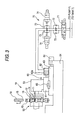
- Fig. 3 is an explanatory diagram for describing a pressure unit.
- Fig. 4 is a diagram for describing the machining of an end face of a work using an elastic cup grinding wheel.
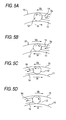
- Fig. 5 is an explanatory diagram for describing a relationship among peripheral speeds of an inner disk, a cage and a drive belt for stably rotating a roller in a cage pocket.
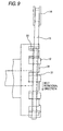
- Figs. 6 to 12 show a diagram for describing a machining apparatus of an end face of a work according to other embodiments of the present invention. Note that in this embodiment, a work for a cylindrical roller as a work is taken as an example.
- a machining apparatus 10 of an end face of a work includes a spindle 50 for rotating, revolving and supporting works 12, a charge unit 51 and a discharge unit 52 for continuously charging the works 12 to and discharging the works 12 from the spindle 50, a spindle grinding wheel unit 53 including an elastic cup grinding wheel 19 as an elastic machining tool, and a pressure unit 60 for pressing the elastic cup grinding wheel 19 to an end face of the works 12 at a fixed pressure.
- the spindle 50 spindle includes a rotatable inner disk 11, a cage 14 including pocket portions 13 for holding the plurality of works 12 substantially at equal intervals in a peripheral direction at an outer diameter portion of the inner disk 11 and rotatable independently from the inner disk 11, and the drive belt 15 hung over the outer diameter portions of the plurality of works 12 held by the inner disk 31 and the cage 14.
- the inner disk 11 and the cage 14 are disposed to be within an axial direction length of the work 12 to prevent the inner disk 11 and the cage 14 from interfere with the elastic cup grinding wheel 19.
- the inner disk support hollow shaft 16 As shown in Fig. 1, mounted on the inner disk support hollow shaft 16 as an inner disk driving shaft so that the inner disk 11 and the cage 14 can be rotated concentric independently of each other.
- the cage 14 is mounted on a cage support shaft 17 as a cage driving shaft.
- the driving belt 15 is driven by a drive motor not shown through a pulley 18.
- the charge unit 51 is configured to automatically supply works 12 continuously to a charge position of the spindle 50 and the discharge unit 52 to automatically discharge works continuously from the discharge position of the spindle 50.
- the discharge unit 52 By rotating the inner disk 11, the cage 14 and the drive belt 15 at predetermined rotational speeds, the end face of the work can be machined while rotating and revolving the work 12 continuously.
- two spindle grinding wheel units 53 are arranged.
- Cup grinding wheels 19 for machining the end face of the work 12 are pressed to the end faces of the works 12 from directions inverse to each other at two locations, and by arranging stoppers 20 at end faces of the works 12 on sides opposed to the pressing faces, the two end faces of the work 12 are made to be able to be machined.
- an angle of the cup grinding wheel 19 relative to the end face of the work 12 an angle of crowning (refer to Fig. 14) can be adjusted.
- the elastic deformation of the elastic cup grinding wheel 19 where the elastic cup grinding wheel 19 is in contact with the end face of the work 12 results in machining according to pressure distribution P shown in Fig. 4A.
- the elastic cup grinding wheel 19 is therefore pressed to the end face of the work 12
- the highest pressure is obtained at a portion of connecting the plane portion of the end face of the work and the chamfer face 3 and the portion is machine more, thus making it possible to obtain a smoothly continuous crowned shape (refer to Fig. 4B).
- the end face of the work is machined with a hardly elastic tool, the portion where the machining tool interferes with the work 12 is removed. This causes an edge between the worked portion and the non-worked portion, thus making it impossible to obtain a smoothly continuous crowned shape.
- the longer it is used for machining the more worn the elastic cup grinding wheel 19 will be.
- the elastic cup grinding wheel 19 is pressed to the end face of the work 12. Even when worn, the elastic cup grinding wheel 19 can therefore machines the end face of the work 12 always at a constant machining force with stable machining amount and with little shape difference.
- the pressure unit 60 is disposed on the spindle 50 and the common bed 54 and includes a pressure slide table 61 for placing a spindle grinding wheel unit 53 thereon and cable of pressing an elastic cup grinding wheel 19 to an end face of a work 12 at a fixed pressure when advancing, a pressure actuator 62 for hydraulically driving the pressure slide table 61 through a hydraulic circuit 70, a positioning slide table 63 for slidably placing thereon and positioning the pressure slide table 61 in a predetermined position, a positioning actuator 64 for driving the positioning slide table 63, and a linear gauge 65 provided between the pressure slide table 61 and the positioning slide table 63 for measuring the position of the pressure slide table 61 when the end face of the work 12 is machined.
- a pressure slide table 61 for placing a spindle grinding wheel unit 53 thereon and cable of pressing an elastic cup grinding wheel 19 to an end face of a work 12 at a fixed pressure when advancing
- a pressure actuator 62 for hydraulically driving the pressure slide table 61 through a hydraulic circuit 70
- the pressure slide table 61 is guided by a linear guide, an air slide, and the like and the slide resistance for the guide is set to a sufficiently small value respective to the elastic cup grinding wheel 19's force for machining the end face of a work and pressurizing force.
- the pressure actuator 62 supplies oil to or discharges oil from the right- or left-side oil chamber of a piston 62a through the hydraulic circuit 70 to drive the piston 62a and advance and retreat the pressure slide table 61.
- the positioning slide table 63 is preferably used when increasing the service thickness of the elastic cup grinding wheel 19 via the small-stroke pressure slide table 61 or when accommodating a change in position where the work 12 is set on the spindle 50. If, for example, the elastic cup grinding wheel 19 becomes worn, the position of the operating pressure slide table 61 is kept fixed by controlling the positioning actuator 64 and adjusting the position of the positioning slide table 63, based on linear gauge 65 measurements.
- the linear gauge 65 is used to measure the position of the pressure slide table 61 when machining the end face of the work and monitor the worn state of the elastic cup grinding wheel 19.
- the worn state of the elastic cup grinding wheel 19 can be detected by calculating the difference between the measurements and reference values (for example, measurements for the pressure slide table 61 with a new elastic cup grinding wheel 19 pressed to the end face of a work 12) and the position of the positioning slide table 63.
- the time to replace the elastic cup grinding wheel 19 can also be determined from measurement taken by the linear gauge 65.
- the elastic cup grinding wheel 19 requires grinding wheel grinding that involves natural blade appearance so as to maintain good machining bite thereof and continue correct machining. Unstable contact of the spindle grinding wheel unit 53 with a work 12 would cause uneven working surface and therefore irregularities in the working surface of the elastic cup grinding wheel 19, thus preventing the elastic cup grinding wheel 19 from machining the end face of the work with a correct accuracy.
- a damping action is given to the pressure actuator 62 for driving the pressure slide table 61 to prevent the spindle grinding wheel unit 53 from contacting the work 12 in an unstable manner so that the spindle grinding wheel unit 53 cannot move rapidly.
- a hydraulic circuit 70 for the hydraulically operating pressure actuator 62 therefore has two types of circuits, that is, a circuit with a narrow throttle and a circuit with a wide throttle.
- a switchover is made to the circuit with the wide throttle to transfer the pressure slide table 61 promptly when the elastic cup grinding wheel 19 is pressed to the end face of a work 12 at the start of pressurization and when the elastic cup grinding wheel 19 is retreated from the end face of the work 12 after machining is over.
- a switchover is made to the circuit with the narrow throttle to give a damping action to the movement of the pressure slide table 61.
- the hydraulic circuit 70 is configured to provide oil from the pump P to the left- or right-side oil chamber of the pressure actuator 62 piston 62a through the operation of a main selector valve 71.
- the circuit 70 is also configured to discharge the oil from the right- or left-side oil chamber of the piston 62a to advance or retreat the pressure slide table 61.
- Between the main selector valve 71 and the pressure actuator 62 there are arranged in series two throttle valves (flow control valves with a check valve) with a wide throttle and two throttle valves with a narrow throttle (flow control valves with a check valve, a speed control section).
- Selector vales 74 are arranged in parallel for two throttle valves 73 with a narrow throttle.
- each selector valve 74 When the elastic cup grinding wheel 19 is pressed to the end face of the work 12 at the start of machining and when the elastic cup grinding wheel 19 is retreated from the end face of the work 12 after the end of machining, each selector valve 74 is opened and switched to a circuit with a wide throttle, thereby moving the pressure slide table 61 and/or the spindle grinding wheel unit 53 quickly. During the continued machining of the end face of a work by the elastic cup grinding wheel 19, each selector valve 74 is closed and switched to a circuit with a narrow throttle, thereby providing a damping action to the movement of the pressure slide table 61.
- Young's modulus of the elastic grinding wheel is proper to be 10MPa through 1000MPa, different from a double headplane grinder in which a grinding wheel and a roller is in parallel with each other, when an angle is provided between the cup grinding wheel 19 and the roller 12 constituting the roller as described above, Young's ratio of the elastic grinding wheel is proper to be 50Mpa through 1000Mps which is slightly harder.
- Fig. 5 illustrates a relationship among speeds of the work 12, the inner disk 11, the cage 14, and the drive belt 15.
- Fig. 5A shows a state in which the cage 14 exerts a drive force of revolution, the inner disk 11 rotates in a direction reverse to that of the cage 14, and the work 12 is pressed to the cage 14.
- a rotational speed of the cage 14 is designated by rotation Vc
- a rotational speed of the inner disk 11 is designated by notation Vi
- a speed of the drive belt 15 is designated by notation Vb
- Fig. 5B shows a state in which the cage 14 exerts the drive force of revolution, the drive belt 15 is rotated in a direction reverse to that of the cage 14, and the work 12 is pressed to the cage 14.
- Vc rotational speedof the cage 14
- Vi rotation of the inner disk 11
- Vb speed of the drive belt 15
- ⁇ is preferably about 1.01 through 1.10.
- Fig. 5C shows a case of constituting a state in which the cage 14 brakes revolution of the roller 12.
- Fig. 5D shows a case constituting a state in which the cage 14 brakes revolution of the roller 12 and in which the roller 12 is rotated in a reverse direction.
- an end face of a work 12 is machined using an elastic machining tool 19 while rotating and revolving the work 12 through a spindle. Therefore, the rotation of the work 12 is kept stable and the accuracy of roller end face runout with outside surface can be improved. Further, the end face of works 12 continuously provided by a charge unit 51 is machined with an elastic machining tool 19. Therefore, a smoothly continuous crowned shape can be continuously machined at the end face of the roller with a high efficiency.
- the elastic cup grinding wheel 19 is pressed to the end face of the works 12 with a pressure unit 60 at a fixed pressure for machining purposes. Therefore, the end face of works 12 can be machined in a constant machining amounts without being affected by shape differences in the end face of works 12 before machining. Shape differences in the end face of works 12 after machining can also be reduced.
- a machining apparatus 10 of an end face of a roller includes a spindle 80 for rotating, revolving and supporting works 12, a charge unit 51 and a discharge unit 52 for continuously charging the works 12 to and discharging the works 12 from the spindle 80, a spindle grinding wheel unit 53 including an elastic cup grinding wheel 19 as an elastic machining tool, and a pressure unit 60 for pressing the elastic cup grinding wheel 19 to an end face of the works 12 at a fixed pressure.
- the spindle 80 spindle includes a rotatable inner disk 31, a cage 34 including pocket portions 33 for holding the plurality of rollers 12 substantially at equal intervals in a peripheral direction at an outer diameter portion of the inner disk 31 and rotatable independently from the inner disk 31, and the drive belt 15 hung over the outer diameter portions of the plurality of works 12 held by the inner disk 31 and the cage 34 and the pocket portions 33 of the cage 34 are constituted by a comb-like shape each for supporting the outer diameter face and one end face of the roller 12.
- the work 12 is provided with a rotational movement and by rotating the cage 34, the work 12 is provided with a revolutional movement.
- the inner disk 31 is attached to an inner disk support shaft 36 constituting an inner disk drive shaft and the cage 34 is attached to a cage supporting hollow shaft 37 constituting a cage drive shaft such that the inner disk 31 and the cage 34 can be driven coaxially with each other and independently from each other.
- the drive belt 15 is driven by a drive motor not shown via the pulley 18.
- the elastic cup grinding wheel 19 for machining the end face of the work 12 is pressed to the end face of the work 12 at one location and the end face of the work 12 can be machined under the state.
- the angle of crowning (refer to Fig. 14) can be adjusted.
- the end face of the work 12 on one side is supported by the cage 34 and therefore, only the end face on one side of the work 12 can be machined.
- the both end faces of the work 12 it is necessary to machine one sides thereof by using two sets of the kind of the apparatus, even when a length of the work 12 in the axial direction is short and the inner disk and the cage cannot be arranged as in the above-described first embodiment, no problem is posed according to the embodiment.
- the drive belt 15 may be skewed in the axial direction.
- the other constitution and the operation and the effect are similar to those of the above-described first embodiment.
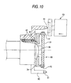
- a machining apparatus of an end face of a work according to a third embodiment of the present invention will be explained below with reference to Fig. 10.
- a dressing tool is added to the spindle 80 according to the second embodiment. Therefore, portions duplicated with those of the above-described first embodiment will be given the same notations in the respective drawings and not be explained.
- machining cannot be impossible with a proper accuracy in some cases if there is a large fluctuation in the working face of the grinding wheel of an elastic cup grinding wheel 19 immediately after grinding wheel replacement, for example.
- the grindingwheel therefore requires dressing.
- a dressing tool having a dresser diamond 91 is pivotably attached to the spindle housing 80 of the spindle 80 via a plurality of roller bearings 82.
- the dressing tool has a dresser diamond 91 that slews around a shaft concentric with the revolving shaft of a work 12 on a spindle 80.
- the dressing tool 90 is turned by means of a drive unit not shown and the elastic cup grinding wheel 19 is dressed with the dresser diamond 19 so that the end face of a work 12 can be machined with a proper accuracy.
- the elastic cup grinding wheel 19 is driven together with a spindle grinding wheel unit 53 by means of the pressure unit 60.
- the pressure slide table 61 is therefore pressed to the advance or retreat end thereof and fixed.
- the positioning slide table 63 is positioned in a suitable position based on a dressing cut amount determined by the thickness of the elastic cup grinding wheel 19 and the position of the dresser diamond 91.
- the elastic cup grinding wheel 19 is dressed by turning the dresser diamond 91 under the above condition.
- the position of the positioning slide table 63 can be pre-determined based on the thickness of the elastic cup grinding wheel 19 and the setting position and mechanical configuration dimensions of the dresser diamond 91.
- the position of the positioning slide table 63 can be pre-determined based on the position of the pressure slide table 61 measured with a linear gauge 65 at the machining of the end face of the work 12, the positioning position and mechanical configuration dimensions of the positioning slide table 63, and the setting position of the preset dresser diamond 91.
- the other constitution and the operation and the effect are similar to those of the above-described second embodiment.
- a machining apparatus of an end face of a work according to a fourth embodiment of the present invention will be explained below with reference to Fig. 11. Further, portions duplicated with those of the above-described first and second embodiments will be given the same notations in the respective drawings and not be explained.
- a machining apparatus 100 of an end face of a work includes a spindle 59 (or spindle 80) for rotating, revolving and supporting works 12 and two charge units 51 and two discharge units 52 for continuously charging the works 12 to and discharging the works 12 from the spindle 50 (80).
- the machining apparatus 100 includes two elastic cup grinding wheels 19 spaced apart opposite side from each other and a pressure unit 60 for pressing the elastic cup grinding wheel 19 to an end face of the works 12 at a fixed pressure. Each elastic cup grinding wheel 19 is driven by the pressure unit 60 together with the spindle grinding wheel unit 53. Further, the configuration of the spindle grinding wheel unit 53 and pressure unit 60 for driving the elastic cup grinding wheel 19 is the same as in the first embodiment and not illustrated.
- the works 12 continuously supplied are rotated and revolved via the spindle 50 (80) and machined with the elastic cup grinding wheel 19 pressed to the end face of the works 12 at a fixed pressure by means of the pressure unit 60 to machine.
- the works are then discharge from the other discharge unit 52. In this way, both end faces of the works 12 are machined.
- the two elastic cup grinding wheels 19 are aligned for adjustments so that they are slighted tilted with respect to the end face of the works rotated and revolved via the spindle 50 (80).
- the rotation axis of the elastic cup grinding wheel 19 is first tilted by a predetermined angle ⁇ 1 with respect to the revolution axis of the work 12 (refer to Figs. 11C and 11D). It is desirable to widen the entrance-side (supply-side) intervals and narrow the exit-side (discharge-side) intervals when the work 12 enter the machining portion of the elastic cup grinding wheel 19 by means of revolutional movement.
- the tilting angle ⁇ 1 of the elastic cup grinding wheel 19 is set to prevent the excessive and rapid machining of the work 12 at the entrance side and so that a sufficiently long area can be obtained.
- the rotation axis of the elastic cup grinding wheel 19 is tilted by a predetermined angle 0 2 with respect to the revolution axis of the work 12 to adjust the contact of the elastic cup grinding wheel 19 with the end face of the work 12.
- the crowned shape of the work 12 can be adjusted in case of machining flat the entire end face of the work 12 and in case of machining only the periphery of the portion of connecting the outer diameter face and the chamfer face of the work 12.
- the work 12 is, by the revolutional movement thereof, brought into contact with the entire working face of the elastic cup grinding wheel 19. This provides the wear of the entire working face of the grinding wheel, thus resulting in no remaining local unworn portion thereof.
- the other constitution and the operation and the effect are similar to those of the above-described first or second embodiment.
- aligning adjustment according to the present invention is also applicable in the machining apparatus according to the above-mentioned embodiments.
- machine apparatus of the end face of the work according to the invention is not limited to those of the above-described respective embodiments but can pertinently be modified or improved.
- the end face of the work 12 can be machined by a smoothly continuous crowned shape with excellent swinging accuracy by an abrasive belt 40 having a pertinent tension.
- cylindrical roller is exemplified as the roller to be machined
- the invention is applicable also to a spherical roller.
- the pressure slide table can be used with the position side table to advance the machining tool.
- the pressure slide table may be used alone.
Landscapes
- Engineering & Computer Science (AREA)
- Mechanical Engineering (AREA)
- General Engineering & Computer Science (AREA)
- Grinding Of Cylindrical And Plane Surfaces (AREA)
- Grinding And Polishing Of Tertiary Curved Surfaces And Surfaces With Complex Shapes (AREA)
- Rolling Contact Bearings (AREA)
- Constituent Portions Of Griding Lathes, Driving, Sensing And Control (AREA)
- Grinding-Machine Dressing And Accessory Apparatuses (AREA)
- Finish Polishing, Edge Sharpening, And Grinding By Specific Grinding Devices (AREA)
Applications Claiming Priority (4)
| Application Number | Priority Date | Filing Date | Title |
|---|---|---|---|
| JP2004073926 | 2004-03-16 | ||
| JP2004073926 | 2004-03-16 | ||
| JP2005037614A JP2005297181A (ja) | 2004-03-16 | 2005-02-15 | ワーク端面の加工装置、加工方法、ころおよびころ軸受 |
| JP2005037614 | 2005-02-15 |
Publications (2)
| Publication Number | Publication Date |
|---|---|
| EP1577057A2 true EP1577057A2 (fr) | 2005-09-21 |
| EP1577057A3 EP1577057A3 (fr) | 2006-03-29 |
Family
ID=34840241
Family Applications (1)
| Application Number | Title | Priority Date | Filing Date |
|---|---|---|---|
| EP05005612A Withdrawn EP1577057A3 (fr) | 2004-03-16 | 2005-03-15 | Procédé et dispositif d'usinage de la face d'extrémité d'une pièce, d'un galet et d'un roulement à rouleaux |
Country Status (3)
| Country | Link |
|---|---|
| US (1) | US7182676B2 (fr) |
| EP (1) | EP1577057A3 (fr) |
| JP (1) | JP2005297181A (fr) |
Cited By (8)
| Publication number | Priority date | Publication date | Assignee | Title |
|---|---|---|---|---|
| CN101415524B (zh) * | 2006-03-29 | 2010-09-29 | 株式会社捷太格特 | 制造轮子用滚动轴承装置的方法 |
| EP2319657A1 (fr) * | 2009-11-06 | 2011-05-11 | Supfina Grieshaber GmbH & Co. KG | Rectifieuse plane avec un actionnement supplémentaire pour pièces sous une forme de dispositif d'entrainement à courroie |
| CN102189453A (zh) * | 2011-04-02 | 2011-09-21 | 长治市滚动轴承制造有限公司 | 端面修整器 |
| CN102189454A (zh) * | 2011-04-02 | 2011-09-21 | 长治市滚动轴承制造有限公司 | 轴承端面修整器 |
| US8613643B2 (en) | 2009-04-09 | 2013-12-24 | Ntn Corporation | Work feeder for roller end face working machine, roller end face working machine and rollers for roller bearing |
| CN103921178A (zh) * | 2014-04-28 | 2014-07-16 | 洛阳轴研科技股份有限公司 | 一种圆柱滚子端面的磨削方法 |
| RU2615669C1 (ru) * | 2015-10-29 | 2017-04-06 | Открытое акционерное общество "Московское машиностроительное предприятие имени В.В. Чернышёва" | Абразивно-отрезной станок |
| CN117506569A (zh) * | 2023-12-12 | 2024-02-06 | 安徽光智科技有限公司 | 一种镜片倒角加工方法、装置、计算机设备和存储介质 |
Families Citing this family (17)
| Publication number | Priority date | Publication date | Assignee | Title |
|---|---|---|---|---|
| SG134176A1 (en) * | 2006-01-09 | 2007-08-29 | Giken Sakata S Ltd | An apparatus for grinding a work piece |
| DE202009011327U1 (de) * | 2009-08-20 | 2009-11-26 | Zahoransky Ag | Schleifvorrichtung |
| JP5522569B2 (ja) | 2010-01-26 | 2014-06-18 | Ntn株式会社 | ころの製造方法 |
| CN102275108A (zh) * | 2011-08-25 | 2011-12-14 | 濮阳贝英数控机械设备有限公司 | 圆柱滚子双端面磨削装置及磨削方法 |
| JP6088271B2 (ja) * | 2013-01-31 | 2017-03-01 | 和夫 小柴 | 研磨用工具 |
| JP6303568B2 (ja) * | 2014-02-13 | 2018-04-04 | 株式会社ジェイテクト | 円すいころの研削装置及び円すいころの研削方法 |
| JP6256076B2 (ja) * | 2014-02-13 | 2018-01-10 | 株式会社ジェイテクト | 円すいころの研磨装置及び円すいころの研磨方法 |
| JP6211451B2 (ja) | 2014-04-07 | 2017-10-11 | 株式会社ジェイテクト | 円すいころの端面の加工装置及び砥石体 |
| CN104400634B (zh) * | 2014-10-29 | 2017-06-06 | 洛阳轴研科技股份有限公司 | 一种薄壁轴承端面的磨削装置及方法 |
| JP6485165B2 (ja) * | 2015-03-30 | 2019-03-20 | 日本精工株式会社 | 円すいころの端面研削装置、円すいころの製造方法、円すいころ軸受の製造方法、及び、回転機器の製造方法 |
| CN105415116B (zh) * | 2015-11-27 | 2018-01-26 | 芜湖银星汽车零部件有限公司 | 一种用于机油滤清器座端面磨削的执行器 |
| JP6827768B2 (ja) * | 2016-10-26 | 2021-02-10 | コマツNtc株式会社 | 研削盤 |
| CN108436703B (zh) * | 2018-03-27 | 2023-11-14 | 侯亚新 | 一种基于圆锥滚子球基面的立式复合加工机床 |
| CN110125798A (zh) * | 2019-06-19 | 2019-08-16 | 北京石油化工学院 | 一种偏心行星轨迹多尺寸卡盘的自动磨印石机 |
| CN112223046B (zh) * | 2020-10-21 | 2022-08-02 | 江西世星科技有限公司 | 一种芯片磨片机 |
| CN119077585B (zh) * | 2024-08-23 | 2025-04-25 | 江苏联动轴承股份有限公司 | 一种用于轴承生产的轴承圈抛光装置 |
| CN119282903A (zh) * | 2024-11-20 | 2025-01-10 | 西南交通大学 | 一种轴承滚子跑合法超精密抛光装置及方法 |
Family Cites Families (13)
| Publication number | Priority date | Publication date | Assignee | Title |
|---|---|---|---|---|
| US2551568A (en) * | 1947-12-29 | 1951-05-01 | Timken Roller Bearing Co | Grinder for the spherical ends of rollers |
| US2754635A (en) * | 1952-10-06 | 1956-07-17 | Federal Mogul Bower Bearings | Machine for end-grinding tapered rollers |
| IT942788B (it) * | 1971-11-03 | 1973-04-02 | Riv Officine Di Villar Perosa | Procedimento e dispositivo per la rettifica delle facce di estremita di corpi cilindrici in particolare di rulli per cuscinetti a rotolamen to |
| CH556217A (de) * | 1972-08-28 | 1974-11-29 | Sim Sa Ets | Planschleifmaschine. |
| DE2636689A1 (de) | 1976-08-14 | 1978-02-16 | Hans Dipl Ing Modler | Maschine zum schleifen von profilierten werkstuecken |
| JPS5934502A (ja) * | 1982-08-20 | 1984-02-24 | Tochigi Kouseki Kk | 光フアイバコネクタ用端面研摩機 |
| US4531327A (en) * | 1983-04-25 | 1985-07-30 | Ex-Cell-O Corporation | Centerless grinding machine with ferris wheel arrangement |
| JPH07205001A (ja) * | 1993-11-16 | 1995-08-08 | Tokyo Seimitsu Co Ltd | ウェーハ面取り機 |
| JP3539770B2 (ja) | 1994-08-31 | 2004-07-07 | Ntn株式会社 | 自動調心ころ軸受用ころ及びその加工方法 |
| JP3455411B2 (ja) | 1998-01-21 | 2003-10-14 | 光洋機械工業株式会社 | 両頭平面研削盤 |
| JP2002086336A (ja) * | 2000-09-11 | 2002-03-26 | Disco Abrasive Syst Ltd | 円筒ころ軸受研磨装置 |
| ITBO20010268A1 (it) * | 2001-05-07 | 2002-11-07 | Marposs Spa | Apparecchiatura per il controllo del diametro di porzioni eccentrichedi un pezzo meccanico durante la lavorazione su una rettificatrice |
| JP2003021145A (ja) | 2001-07-05 | 2003-01-24 | Nsk Ltd | ころ軸受 |
-
2005
- 2005-02-15 JP JP2005037614A patent/JP2005297181A/ja active Pending
- 2005-03-15 EP EP05005612A patent/EP1577057A3/fr not_active Withdrawn
- 2005-03-16 US US11/080,560 patent/US7182676B2/en not_active Expired - Fee Related
Cited By (8)
| Publication number | Priority date | Publication date | Assignee | Title |
|---|---|---|---|---|
| CN101415524B (zh) * | 2006-03-29 | 2010-09-29 | 株式会社捷太格特 | 制造轮子用滚动轴承装置的方法 |
| US8613643B2 (en) | 2009-04-09 | 2013-12-24 | Ntn Corporation | Work feeder for roller end face working machine, roller end face working machine and rollers for roller bearing |
| EP2319657A1 (fr) * | 2009-11-06 | 2011-05-11 | Supfina Grieshaber GmbH & Co. KG | Rectifieuse plane avec un actionnement supplémentaire pour pièces sous une forme de dispositif d'entrainement à courroie |
| CN102189453A (zh) * | 2011-04-02 | 2011-09-21 | 长治市滚动轴承制造有限公司 | 端面修整器 |
| CN102189454A (zh) * | 2011-04-02 | 2011-09-21 | 长治市滚动轴承制造有限公司 | 轴承端面修整器 |
| CN103921178A (zh) * | 2014-04-28 | 2014-07-16 | 洛阳轴研科技股份有限公司 | 一种圆柱滚子端面的磨削方法 |
| RU2615669C1 (ru) * | 2015-10-29 | 2017-04-06 | Открытое акционерное общество "Московское машиностроительное предприятие имени В.В. Чернышёва" | Абразивно-отрезной станок |
| CN117506569A (zh) * | 2023-12-12 | 2024-02-06 | 安徽光智科技有限公司 | 一种镜片倒角加工方法、装置、计算机设备和存储介质 |
Also Published As
| Publication number | Publication date |
|---|---|
| JP2005297181A (ja) | 2005-10-27 |
| US7182676B2 (en) | 2007-02-27 |
| EP1577057A3 (fr) | 2006-03-29 |
| US20050233683A1 (en) | 2005-10-20 |
Similar Documents
| Publication | Publication Date | Title |
|---|---|---|
| US7182676B2 (en) | Machining apparatus and machining method of work end face, roller and roller bearing | |
| US6682403B1 (en) | Grinding machine with two grinding wheels | |
| US5664991A (en) | Microfinishing and roller burnishing machine | |
| US8172644B2 (en) | Grinding machine and grinding method | |
| US11383342B2 (en) | Method and cylindrical grinding machine for centerless cylindrical grinding | |
| KR100745017B1 (ko) | 자동연마장치 및 그 제어방법 | |
| EP1297926B1 (fr) | Procédé et dispositif pour polir des surfaces de pièces pour leur donner une superfinition avec des micro-poches d'huile | |
| US20020052165A1 (en) | On-line roll grinding apparatus, on-line roll grinding method rolling mill equipment and rolling method | |
| US4361987A (en) | Apparatus for high tolerance polishing of a work-piece surface | |
| JPH11251272A5 (fr) | ||
| JPH06335715A (ja) | オンラインロール研削装置を備えた圧延機 | |
| JP3583264B2 (ja) | 平面研削方法及び平面研削装置 | |
| WO2022071190A1 (fr) | Dispositif de meulage à rouleaux et support | |
| JP3765136B2 (ja) | ネジを研削する方法 | |
| JP3857579B2 (ja) | 面取り加工方法および面取り加工装置 | |
| JPS63162156A (ja) | ロ−ラバニツシング方法およびその装置 | |
| EP4620618A1 (fr) | Procédé de superfinition, procédé de fabrication de roulement à rouleaux, procédé de fabrication de véhicule, procédé de fabrication de machine et dispositif de superfinition | |
| JP3212444B2 (ja) | オンライン圧延ロール研削装置を備えた圧延機及び研削方法 | |
| JPH04159066A (ja) | 心無研削盤 | |
| JPH0839115A (ja) | オンライン圧延ロール研削方法 | |
| JP2004243483A (ja) | ラッピング加工装置 | |
| EP1258316A2 (fr) | Dispositif d'affûtage de pièces | |
| JPH03221369A (ja) | ローラバニッシュ加工機 | |
| JPS60199511A (ja) | 圧延機のロール研削方法 | |
| JP2023022501A (ja) | 溝研削装置 |
Legal Events
| Date | Code | Title | Description |
|---|---|---|---|
| PUAI | Public reference made under article 153(3) epc to a published international application that has entered the european phase |
Free format text: ORIGINAL CODE: 0009012 |
|
| AK | Designated contracting states |
Kind code of ref document: A2 Designated state(s): AT BE BG CH CY CZ DE DK EE ES FI FR GB GR HU IE IS IT LI LT LU MC NL PL PT RO SE SI SK TR |
|
| AX | Request for extension of the european patent |
Extension state: AL BA HR LV MK YU |
|
| PUAL | Search report despatched |
Free format text: ORIGINAL CODE: 0009013 |
|
| AK | Designated contracting states |
Kind code of ref document: A3 Designated state(s): AT BE BG CH CY CZ DE DK EE ES FI FR GB GR HU IE IS IT LI LT LU MC NL PL PT RO SE SI SK TR |
|
| AX | Request for extension of the european patent |
Extension state: AL BA HR LV MK YU |
|
| RIC1 | Information provided on ipc code assigned before grant |
Ipc: B24D 13/14 20060101ALI20060209BHEP Ipc: B24B 7/16 20060101AFI20050617BHEP |
|
| 17P | Request for examination filed |
Effective date: 20060627 |
|
| AKX | Designation fees paid |
Designated state(s): DE |
|
| STAA | Information on the status of an ep patent application or granted ep patent |
Free format text: STATUS: THE APPLICATION HAS BEEN WITHDRAWN |
|
| 18W | Application withdrawn |
Effective date: 20090609 |